Fiddling about with LEDs again.

Soldato
Joined
13 Jul 2009
Posts
7,175
Location
Llanelli
This time it's SMD LEDs. SMD stands for Surface Mount Device and is normally a LED you would find wave soldered onto a PCB like a graphics card or motherboard.

These little SMD LEDs are bright, very bright.

I have some 1206 sized ones in my drawer. They are just 3.2 x 1.6mm x 1.1mm in size and are quite difficult to solder by hand but achievable even with my nerves. The smallest available are 0402 and are only 1.0 x 0.5 and probably would be beyond my soldering skills.

Under a magnifier

magnify.jpg


Here's one all wired up and ready to go.

smd-unlit.jpg


Let there be light. (470 ohm resistor)

smd-lit.jpg


The biggest difference between 3mm and 5mm LEDs is the field of view. These SMD LEDs give a far better spread of light. I think these Orange ones have a 120 degree FOV, 3mm tend to have 20 degrees. SMD are far more suitable for case lighting than 3mm or 5mm standard package LEDs. With standard LEDs you just get a circle of intense light

5mmLEDcircle.jpg


So I wired 5 in series on a 56 ohm resistor.

Here are those five SMD lighting up an IPA tin with the colour far more blended.

smd-ipa-tin.jpg


I put them in a wicker basket (just something I had to hand). It completely fills the confined space with rich Orange colour.

smd-lit-wickerbasket.jpg


Incredible how much light these tiny things create. My camera is pretty rubbish but you can see the orange tint to the room from just five tiny LEDs.

smd-lit-room.jpg


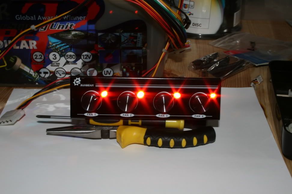
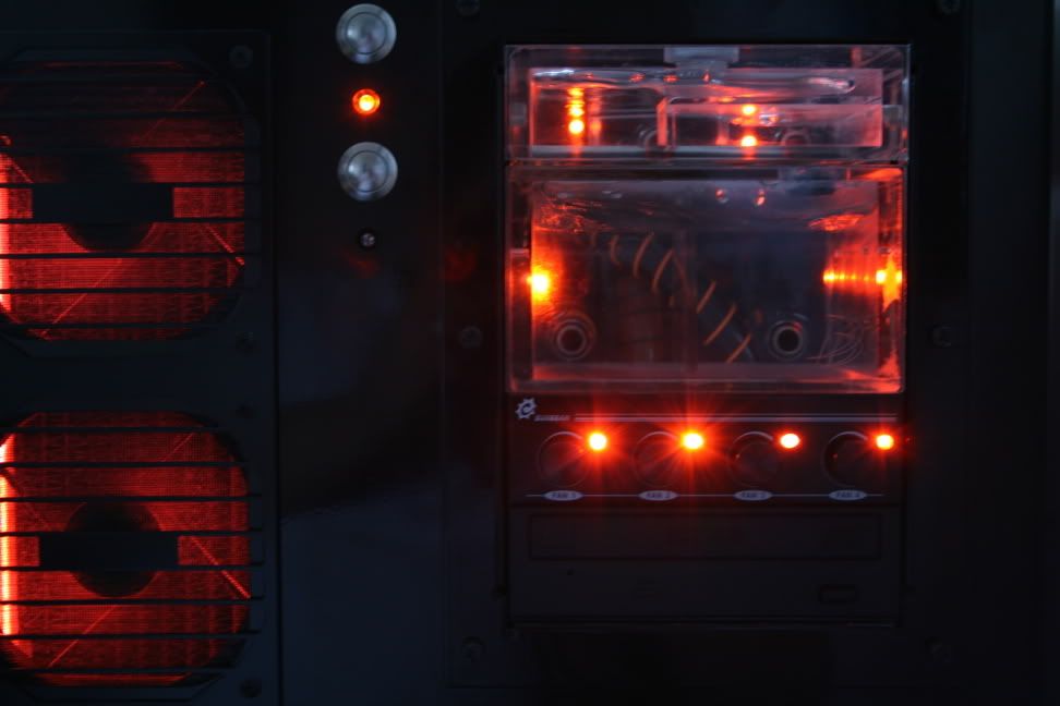
I currently have a 10x 5mm LED string of LEDs inside my case giving me this sort of lighting.

TealcPC.jpg


I so wished I'd painted the inside of my case Black now.

It looks a bit pants I'm sure you'll agree, but from the outside I have nice Orange colour bleeding through the rear fan slot and the top fan slot that throws a nice honeycomb pattern on the wall.

orange-glow.jpg


orange-honeycomb.jpg


So what's the point in this post? Well I know a lot of you guys like lighting up your cases and just thought this post may be helpful when deciding on how to go about doing it.

Total cost of this assembly, about 36p.
 
Soldato
Joined
12 Feb 2007
Posts
14,118
Location
South Shields
They are nice and bright for their size, they are quite simple to hand solder, just use a flux pen to help the solder. You can buy different FOV of 3 and 5mm LED's, just they are less common than the ones seen on eBay.
 
Soldato
OP
Joined
13 Jul 2009
Posts
7,175
Location
Llanelli
Yes flux pen, tweezers and magnifier on order already.

I did look out for high fov 3mm/5mm LEDs but didn't spot many. Thought these more discrete.
 
Soldato
OP
Joined
13 Jul 2009
Posts
7,175
Location
Llanelli
So I wired up 4 little chains of 5 and stuck them to a few long strips of Insulation tape with hot glue, then wired it up to a fan header.

ledstrip1.jpg


One of the LEDs decided to play silly beggars so I bridged the connection.

ledstrip2.jpg


Still a fair bit of light from the array. Here it is shining into my plate drawer.

ledstrip3.jpg


Upon putting it in my case I realised a few things.

1) It was too long to fit in my case. :( (Should have measured and stopped at 3 sets)

2) Noctua cooler completely blocks 90% of light reaching the lower parts of case. :(

3) SMD LEDs are not very robust when soldered with wires. One group of 5 immediately decided to switch off. :(

4) My 4 channel fan controller only has 2 working channels, which is a pain as it already controls 2 fans. :(

5) My existing LED wiring provides a better lighting experience.

So a bit of a fail really. I took the thing back out for reworking and swapping power connector for something more traditional.

Next project is to mount Orange LEDs on an existing LED strip.

Then I will try something with 3mm and 5mm Flat Top LEDs and some wires and see how that works out. I'm thinking something like the new NZXT Sleeved Led http://www.nzxt.com/new/products/case_accessories/sleeved_led_kit
 
Soldato
Joined
25 Aug 2010
Posts
5,216
those NZXT sleeved led's look amazing.

your work is cool, but i gotta say i hate that orange glow lol.

hope u have better luck with ur next project
 
Soldato
OP
Joined
13 Jul 2009
Posts
7,175
Location
Llanelli
So after some chopping in half of LED strip I decided to have a little look how this thing would work inside my messy case.

I must say I wasn't particularly impressed in the daytime.

orange-10strip2.jpg


However once the ambient light level dropped things began to look a lot better.

orange-10strip3.jpg


orange-10strip1.jpg


Gives a very different lighting effect to standard LEDs. I think I would need to reposition the strip more to the left so it illuminates the other side of the HSF and perhaps another strip at the bottom of the case.

Not a complete failure after all.

Still wish I'd painted the inside though.:(
 
Soldato
OP
Joined
13 Jul 2009
Posts
7,175
Location
Llanelli
So I had a delivery of a 30cm Red LED strip.

The first thing I needed to do was remove the plastic waterproof coating.

rem-plastic2.jpg


Light it up. Still red.
redlit.jpg


Here's one of my orange LEDs next to the existing red.

comparison.jpg


Removal of unwanted LED is a simple process of heating up either side of the SMD LED to melt solder and exerting a small amount of pressure to push it off the contacts.

Adding a fresh bit of solder and flux to the pad helps for the new LED to bond correctly. I also did this to the new LED pads too.

Soldering the new LED in position involves heating one pad on the tape and sliding the LED on top of it, then quickly heating the other side and pushing it down onto it. I don't have any images of this as it's tricky enough to do without trying to take pictures at the same time.

Anyway here's the first LED soldered in position.

comparison2-1.jpg


And 10 minutes later all done

alldone.jpg


Now Red LEDs are 1.8-1.9v @20mA and these Orange LEDs are 2.2-2.8v @20mA so at the moment with this 331ohm resistor they are running at about 15mA. I need these to be about 240ohm. (2.4+2.4+2.4=7.2. 12-7.2 = 4.8v to drop at 20mA = 240 ohm. Two 470ohm resistors in series with each other and in parallel with the 331 reaches about 244 ohm.

470470.jpg


heatshrunk.jpg


And you can see the difference it makes, the first 3 LEDs are running at 20mA and the others at 15mA.

led-brighter.jpg


Bit of an eye sore. I will be getting some SMD 240ohm to replace this contraption.

resistored.jpg


Bunged it in the case during daylight hours.
dryrun.jpg


And in the darkness..
Switched off.
unlit1.jpg


unlit2.jpg


On
lit1.jpg


lit2.jpg


And finally the front of the case in darkness, with door open.

front-view.jpg


This is so much neater than my home made version and easier to work with.
 
Soldato
OP
Joined
13 Jul 2009
Posts
7,175
Location
Llanelli
Beginning to wonder why I still do this and more so why I continue to post my ramblings here. Maybe it's just an excuse for me to do something other than care for the kids or play video games.

Maybe someone someday will be motivated enough by my publicised fiddlings to go and do something really cool.

Anyway a couple of fiddles this week.

First up we have one item I've been wanting to change for a while.

The Sapphire logo on my Vapor-x card glows a nice blue which doesn't really fit the orange glow of everything else.

bluesr.jpg


Here's the little blighter all exposed and nasty
vaporxled.jpg


So I had to order this as it was an odd shape. I managed to find some 2 x 5 x 7 rectangular orange LED which were close enough. But for some reason it didn't work out very well when inserted and only lights the plastic a little bit. I'm a bit nervous fiddling around with a live card inside a PC so may leave this one alone.

This is how it looks now. You can see the glow the LED produces but it doesn't shine like the blue one did.

orangesk.jpg


A work in progress then.

The second one was to re-wire a switch I got from a competitor that was originally white.

whiteswitch.jpg


Popping it open it was simple to find the white LED.

internals.jpg


I'd already purchased some wide angle flat top 3mm LEDs so decided to use them. A quick snip, solder and bend later and it's inside.

switched.jpg


It was a bit fiddly getting it all back together and have it actually switch properly.

noworange.jpg


I did three of them! No pics of that though. :(

Here's it lighting a freshly converted from red 15 LED 30cm strip.

poweringastrip.jpg
 
Associate
Joined
9 Sep 2010
Posts
297
Location
Glasgow
Very bright Teal'c! My eyes! I love how you just fiddle around with the lighting in your case, good job ;)

I would say that the GC lighting might be one to leave alone, never know what it could end up causing in the way of troubles xD
 
Soldato
Joined
25 Aug 2010
Posts
5,216
Teal'c.

im 100% going to mess around with some LED's becasue of your posts.

im a noob when it comes to making stuff like this from scratch but did a lot of electronic work in school (all very basic, but enjoyed it) and have never really done any of it since, till i saw your posts. as soon as i start my build i will for sure be doing some LED mess arounds thanks to you. so continue the work :D

oh and as allways. i dont like the orange :p
 
Soldato
OP
Joined
13 Jul 2009
Posts
7,175
Location
Llanelli
So onto a new mini-project

Inspired by G-Dubs' work with his wonderful switch panels I decided to make one of my own. Hopefully Mr Dubs doesn't mind me repeating his image here.

Photo0565.jpg


I suppose I wish to be able to switch stuff on and off without taking my side panel off but it also gives me something constructive to do, life can sometimes be slow as a foster carer ;)

I did think about buying a ready-made panel that would simply fit in the 5 1/4" drive bay and come pre drilled with the right size holes. I decided that would be no fun at all. :)

I thought it would be a good idea to use a spare drive bay cover and stick something to it. My first choice was a bit of metal but I found it impossible to drill a large enough hole in it without it bending like a mad thing. So I decided on some acrylic instead.

You can see the bent and battered strip of steel that I used. Maybe thicker stock would have worked but I didn't have any, or the tools or a workshop to work it properly.

metalvsplastic.jpg


So I had a bit of acrylic left over from a top fan blocking mod I did a while back.

It looks pretty good mounted with a switch.

fitted1.jpg


Seeing as I was using Acrylic I thought that I might as well light it up with LEDs. The acrylic I had was 3mm and the LEDs were 3mm so I drilled slightly offset to the rear side. Bunged the LEDs in stuck them with a tiny bit of hot glue. I had to drill a small hole in the drivebay cover to achieve this.

ledfitting2.jpg


And from the rear.

ledfitting.jpg


The circuit is pretty simple.

It goes from the switched accessory position on the switch, anode to cathode through 4 LEDs and then I added the resistor (100 ohm) and back to the Ground terminal.

And all lit up on the bench.

switchedon.jpg


And now a few shots of how it looks in the daytime in various states.

All case and fan lights off.
alloff.jpg


Main lights on but panel off
nopanel.jpg


All lights on
allon.jpg


And now night shots, the DVD drive was away during these pictures being painted black.

night-shot.jpg


nightshot2.jpg


I think it looks quite nice. I know Orange isn't to everyone's taste but I do like the warm glow the whole thing gives off.

I may decide to do this again with fresh unmarked thicker acrylic to better accomodate the LEDs (and give better side glow) and fresh switches that weren't damaged by some barbarian as they were opened with metal tools. In fact I've already bought some 6mm acrylic. :)

Total power consumption for case lighting (2 fans (16 & 12 LEDs), 1 cover (4 LEDs), 4 switches (4 LEDs), 2 strips (15 LEDs each)) is only 9.3w. The switch LEDs consume the largest amount per LED because they are wired one per resistor whereas everything else has multiple LEDs per resistor.

Any questions, comments do feel free.
 
Last edited:
Soldato
OP
Joined
13 Jul 2009
Posts
7,175
Location
Llanelli
Wow has it really been that long since LEDs were in my life?

Anyway tried to tart up a Noctua NF-P12 fan before re-introducing it to my machine today.

Added 8x Orange 3mm Ultra bright standard shape LEDs around the spokes, equidistant from the spoke. I'm not sure if I actually like this look but rather the total 360 like on my 16 LED fans.

I also added 8x 3mm flat top Orange LEDs facing the heatsink surface. I'm hoping to get some Orange colour bleed into the Alpenfoehn Brocken that I currently have fitted.
I may actually mod the partner pull fan with the just the 8 flat toppers as the fan surface can't really be seen on the other side of the heatsink.

Noctua1-1.jpg


Noctua2-1.jpg


If this works I will probably mod the Thermalright TY-140 that is sitting on top of my Shaman in a similar fashion to shine some light up onto that heatsink and card.

I also Braided the now 5 cables that this fan uses and fitted an Orange fan connector to the end. It looks quite nice.
 
Back
Top Bottom