Mock loop designs + help with idea for colours

Associate
Joined
3 Nov 2014
Posts
1,541
Location
Newcastle, England
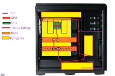
Im finally going for a watercooling loop, and I am busy thinking of ways to do it, I am not 100% on the 2nd GPU, probably not though but stuck it in my first idea as it looked more full :p

MlcSdaM.jpg

I have the specs listed in sig.
I am wondering what my options are, as my mobo (X99 SLI) has like a golden finish to it, however I got this due to pricing and the DDR4 I have is like a pulsing red which I love.
I am not 100% set on a color scheme and would happily sell/buy things to make things the way I am happy with, and I am also confident in modding the case to meet my needs.
I LOVE black combos such as Green, orange, or purple being the 3 best partners along with black individually in my opinion. Red is really nice too and would suit my setup but would like to go out the box, but maybe red will be easier as its my first watercooling loop I dont know.

I am pretty set on hard tubing, and I understand some of the challenges with it, but I am prepared to put the work in, in order to make something I am proud of.

My GPU block is on its way and is the 'Aquacomputer Kryographics Hawaii Radeon R9 290X Full Coverage Liquid Cooling Block - Copper / Acrylic' Drop that into google and take a look.

Any ideas are more than welcome, and help is MASSIVELY appreciated no matter how small.

Cheers!
 
Soldato
Joined
20 Jun 2011
Posts
3,675
Location
Livingston
Bit tight for time. I would try and draw something up but maybe if you flip the rads so the barbs are on the side closest to the front of the case you'll end up with cleaner runs of tubing. Would it all still be visible through your side panel window?

The last and longest tube you have running from the top rad back down to the pump/res will be wobbly. It's a bit long and lacking support where the 90 degree bend is.

You could maybe even make use of the rubber grommets on the motherboard tray and route the tubing behind then down to the pump/res. Or drill a hole large enough to take a bulkhead fitting between the first and second grommet (above the top GPU) then run the tubing on the other side back down to the pump/res.
 
Associate
Joined
5 Sep 2014
Posts
1,692
Location
Glasgow
might be worth looking at some crossflow radiators in your proposed setup ,would make your tubing runs look a fair bit neater
 
Associate
OP
Joined
3 Nov 2014
Posts
1,541
Location
Newcastle, England
Bit tight for time. I would try and draw something up but maybe if you flip the rads so the barbs are on the side closest to the front of the case you'll end up with cleaner runs of tubing. Would it all still be visible through your side panel window?

The last and longest tube you have running from the top rad back down to the pump/res will be wobbly. It's a bit long and lacking support where the 90 degree bend is.

You could maybe even make use of the rubber grommets on the motherboard tray and route the tubing behind then down to the pump/res. Or drill a hole large enough to take a bulkhead fitting between the first and second grommet (above the top GPU) then run the tubing on the other side back down to the pump/res.

Mostly all of it bar the right hand side will be, I may be able to do something with the side but im not sure if i wanna go to that extent yet
 
Soldato
Joined
14 Jul 2005
Posts
8,363
Location
Birmingham
How about using splitters like this:

pMhZ4Pt.jpg.png

So you have the pump outlet rising up toward the CPU but then splitting, so then the top radiator does the CPU alone and the bottom radiator does the GPU alone, then the rad outlets combine back together at the pump inlet.

In my diagram red lines show the pump outlet side (pre rad) and the pink lines show the pump inlet side (post rad). Arrows show direction of flow.

In this configuration you also get flow direction to be through components first, then radiators. I think in yours it was possibly the other way around?
 
Last edited:
Associate
OP
Joined
3 Nov 2014
Posts
1,541
Location
Newcastle, England
How about using splitters like this:

pMhZ4Pt.jpg.png

So you have the pump outlet rising up toward the CPU but then splitting, so then the top radiator does the CPU alone and the bottom radiator does the GPU alone, then the rad outlets combine back together at the pump inlet.

In my diagram red lines show the pump outlet side (pre rad) and the pink lines show the pump inlet side (post rad). Arrows show direction of flow.

In this configuration you also get flow direction to be through components first, then radiators. I think in yours it was possibly the other way around?

That last point didnt even cross my mind! I love the idea of that splitter, would it actually work? In theory it 100% would, and I guess it would in reality too,that is a very good shout.

Another question, I have 4 hard drives 2 of which are SSD's, as I am 99% sure on cutting out the side plate, would it be worth it or should I just remove some of the drive slots and try fit the res in there as is? Or does it look better on show?

Also colour schemes, any ideas?
 
Soldato
Joined
14 Jul 2005
Posts
8,363
Location
Birmingham
I'm not sure what fittings are available as never done this myself. But I would fit a valve on the return pipework from each rad, then if you need to you can balance the flows through each component.

I think the pipework could be reconfigured slightly too to neaten it up more.I would go left out of the pump under the gpu and come vertically up on the left hand side feeding the cpu last. Then come down from the gpu right outletside vertically to the bottom rad. I'll try drawing it later.

Wish I had the cash to do this to my own rig!

Colours is personal preference but I like the pastel ones rather than the translucent.
 
Last edited:
Associate
Joined
13 Feb 2014
Posts
1,130
I love the ideas of the splitter, would like to know if that would actually work

Your going to need some decent pump power to do that otherwise the "Path of least resistance" is going to take far more of the flow.
 
Soldato
Joined
14 Jul 2005
Posts
8,363
Location
Birmingham
I love the ideas of the splitter, would like to know if that would actually work

Your going to need some decent pump power to do that otherwise the "Path of least resistance" is going to take far more of the flow.

Hence the valves on each line.

It should work. You'll get roughly half the pump flow through each half of the loop. Resistance on both halves should be roughly equal if the rads are similarly sized.

I've never done this myself though so 2nd opinion is prudent
 
Soldato
Joined
14 Jul 2005
Posts
8,363
Location
Birmingham
Valves prevent backflow but do nothing to equalise resistance to flow - though I am basing this on human anatomy, not hard plumbing.

Yeah they do. It's called throttling. Same principle with taps (which is just a valve inside). A half open tap has a lower flow rate than a fully open one.

I don't know if they are necessary though. It might be that the flow splits in half with no issues.
 
Last edited:
Soldato
Joined
14 Jul 2005
Posts
8,363
Location
Birmingham
I've done a bit more reading up on this and apparently using splitters is not favoured because of the difficulties getting even flows through blocks with different resistances.

I've also read that the cooling should go through the rads first then the components which seemed the wrong way round to me at first but it means the blocks get the water at its coldest point.

So OP it looks like your optimum setup would be pump to rad1, rad1 to cpu, cpu to rad2, rad2 to gpu(s), gpu(s) to pump.

I guess the main difficulty with your build is having the rads on opposite sides of the case. What you don't want to do is go cpu to gpu or vice versa.
 
Associate
OP
Joined
3 Nov 2014
Posts
1,541
Location
Newcastle, England
Any other ideas for the loop decided to stick to 1 card as I am going to upgrade my card when AMD release their new ones along with a new monitor which I am saving up for now haha.

Let me know ideas!
 
Last edited:
Back
Top Bottom