Project LAZARUS - Skulltrail D5400XS + QX9775

Associate
Joined
29 Jun 2016
Posts
65


PROJECT LAZARUS

Overview
Used to have two PNY Quadro 3700s as this was my CAD rig.
Its no longer really needed for that so after receiving some currys vouchers I threw in the ASUS STRIX GTX 960
I know this won't compare to a modern gaming rig and that the hardware is very outdated. In all honesty I don't even really play a lot of games.
I do however have a soft spot for this machine and love tinkering so this will be watercooling for the sake of watercooling and overclocking more than anything else.

Mainly, I want to push this thing to see what it can really do, and if it can still hold its own.


Aim
No harm in having an idea of the end result. Phase 1 will just be focusing on the hardware and getting a stable overclock.
I can always look at hardline and the other mods once its up and running.
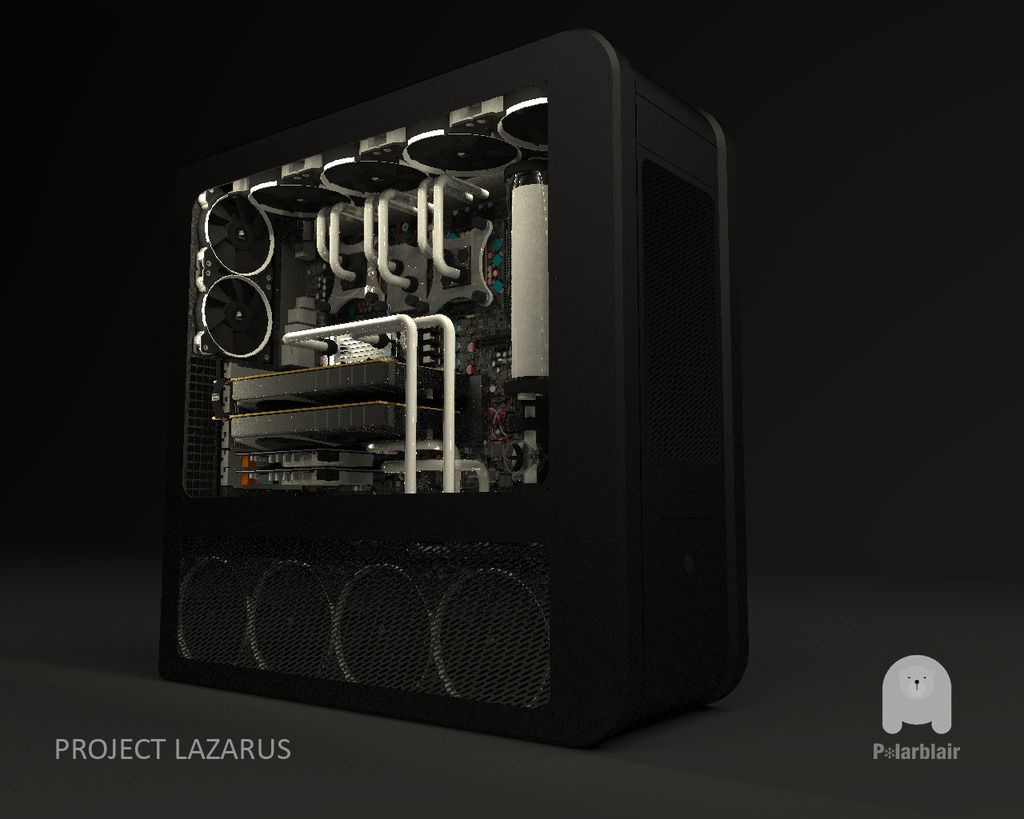
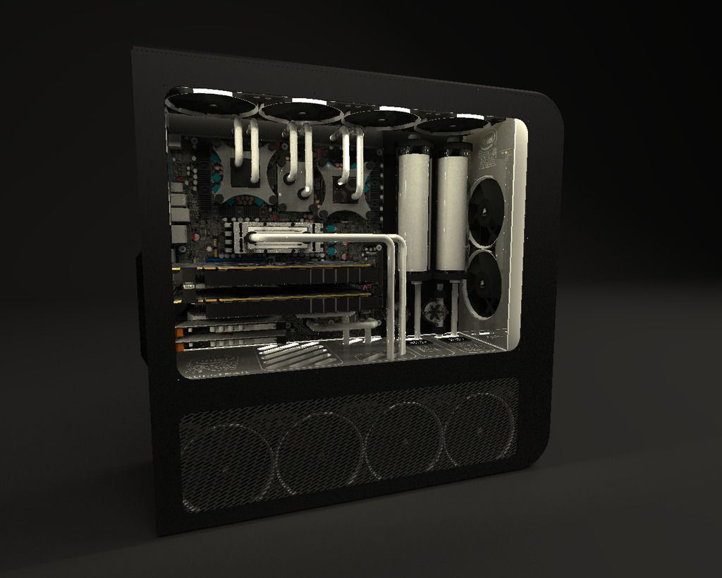
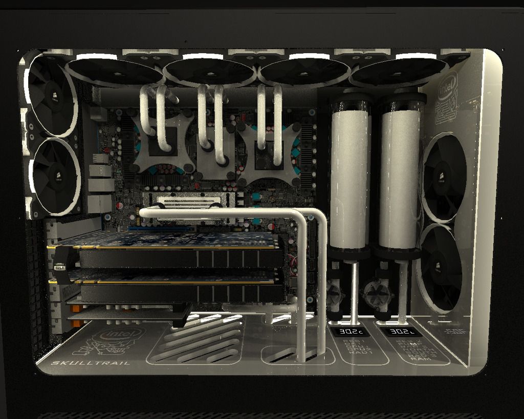
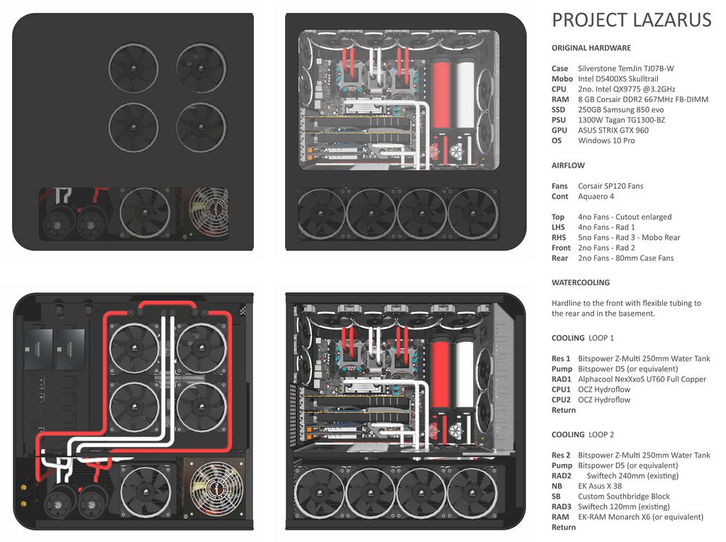
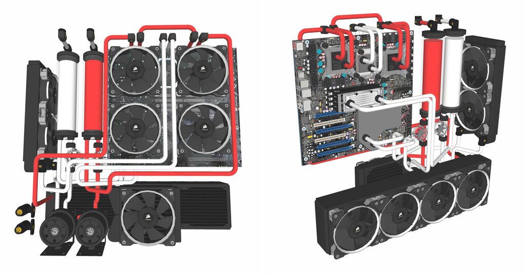
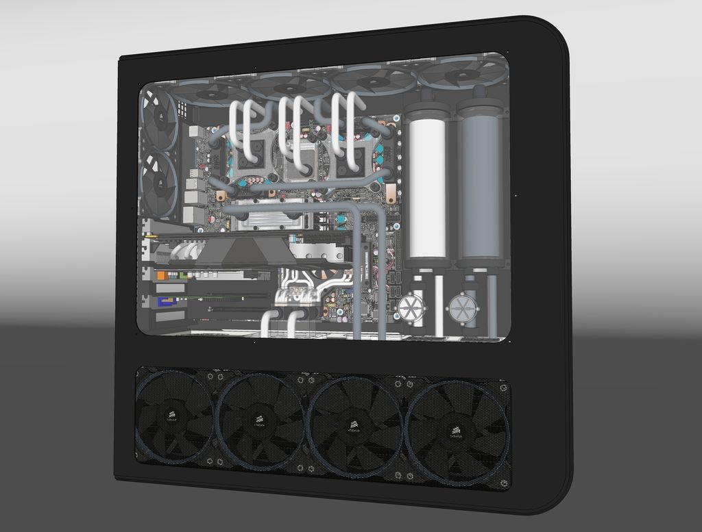
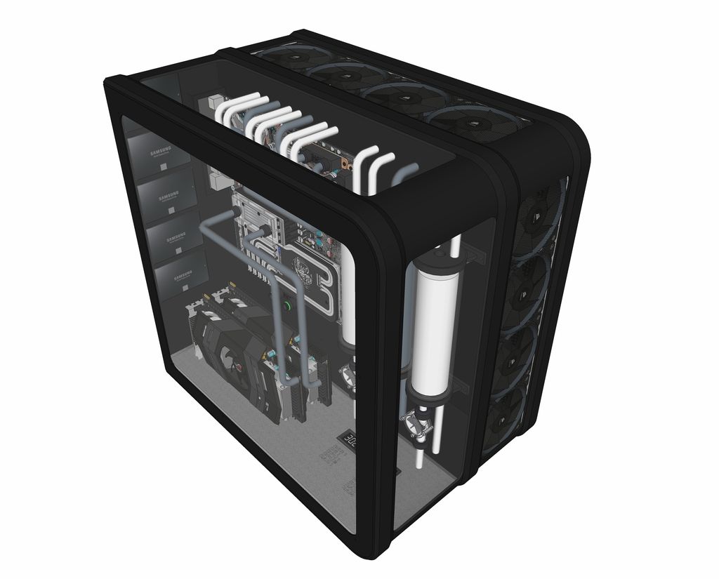
This is my first stab at the design. The loops looks a little messy in the basement but this will all be flexible tubing so less of a worry.
Looking for feedback and obvious mistakes.


Existing Hardware

Going to be reusing most of these parts to keep costs sensible
Parts to be replaced marked red

Case Silverstone TemJin TJ07B-W
Mobo Intel D5400XS Skulltrail - 2no. Intel QX9775 @3.2GHz
CPU 2no. Intel QX9775 @3.2GHz
RAM 8 GB Corsair DDR2 667MHz FB-DIMM
SSD 250gb samsung 850 evo
PSU1300W Tagan TG1300-BZ
GPU ASUS STRIX GTX 960


Outstanding Issues

Fill/ Bleed
Still need to figure out the best place to splice in the bleed valve. Currently have the taps positioned next to the pumps.
Reservoirs are filled from lines accessed on the other side of the case.

Sensor/ Controller
Need some pointers on the control scheme for the waterloop. I already have an Aquaero 4 controller.
If I use fan splitters will this be enough for my purposes? I'm assuming the pumps can be run without electronic control and just set at a constant rate?

Any advice would be appreciated - Thanks for Looking :)
 
Associate
Joined
13 Feb 2014
Posts
1,130
Looking good!

"Can I set the pump at a constant rate?" Just make sure you buy a RPM Pump, most of the D5's etc has a little dial on the back, easy, just don't go PWM etc.

I will point out you have not rendered any cables in there, once you get your GPU power cables in things might look a fair bit different.

If your doing soft tubing, some of your routing wont work, the nice straight bit next to the GPU's will just simply pull itself straight as possible and will past over the top of the them, not sure if you will be happy with that layout.

Thou you don't have a lot of room a T junction off near one of the pump connector would be best for a drain valve, there isn't really anywhere else you can do it without it being visible.

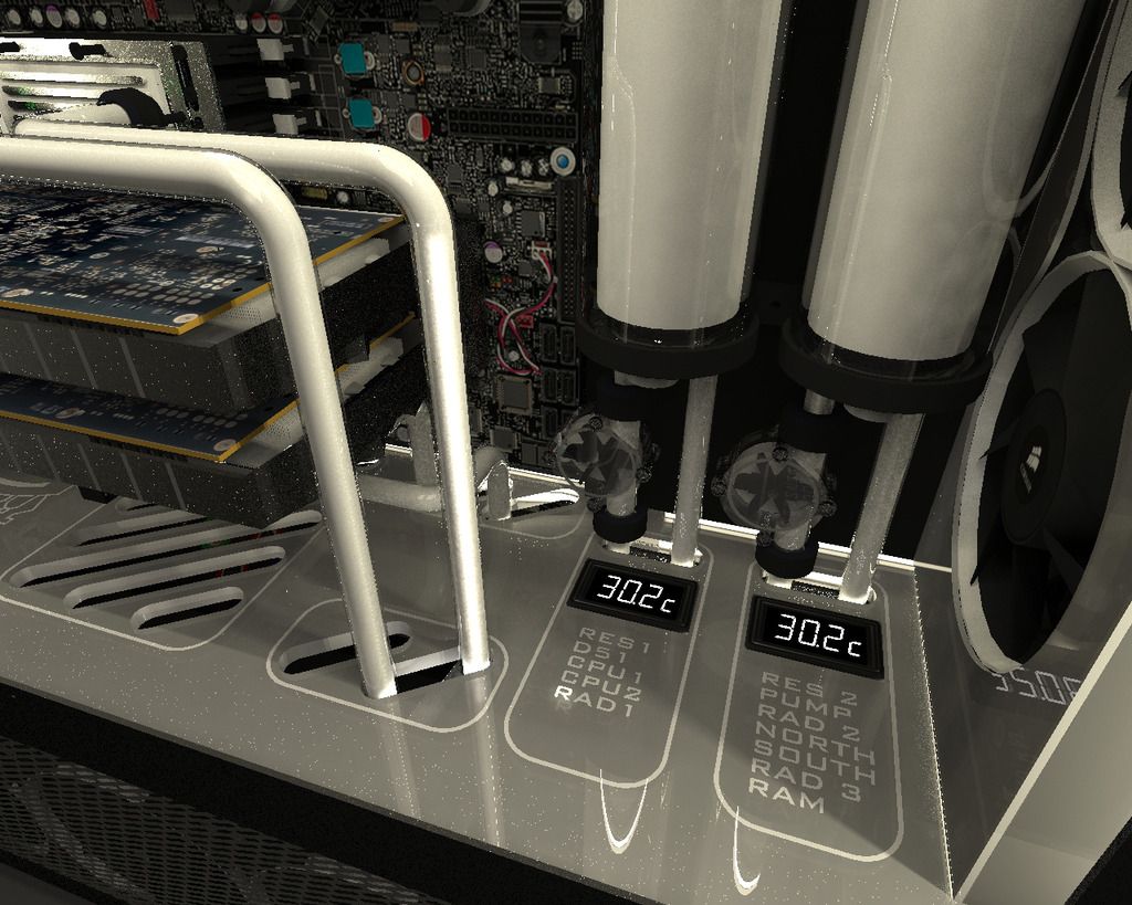
one tiny tiny tiny minor thing, on the bottom of the case you have a list of "What is in each loop" One has a pump one doesn't .. minor thing but sending my OCD mad :D
 
Associate
OP
Joined
29 Jun 2016
Posts
65
Pump
Saw the pumps with the small dials - exactly the answer I was hoping for! Any downsides to this other than lack of variable control?
I'm assuming demand for increased cooling when the system is under load is handled by the fan controller?

Cable Management - or lack thereof
Yup, still need to figure out the cable management but will probably do that hand drawn rather than rendered. Still need to look at sleved cables but general design concept will be the same - route them through to the back of the case at point of contact on the board, then deal with the mess on the other side :)

Loop Material
Everything to the front of the case will be hardline - then going to soft tubing in the basement and the rear of the case for easier management.

Bleed Valve
Does it matter if the T junction is placed at the start of the line or the end? ie connected to the pump inlet or outlet? My understanding was that the pump isnt used to empty the system, rather its a simple gravity drain? Read everywhere that the easiest way to damage a pump is run it dry/without enough liquid.
Is it simply the case to run the bleed valves to the lowest point?

Render goof
Good catch on the render! But your OCD really won't like this - both loops do actually have pumps listed but the left column has it down as 'D51' instead of 'pump' - D'OH!

Cheers!
Thanks for the feedback! I cant make it clear enough that this is my first stab at a build so sanity/idiot checks on the design are not just welcome but a necessity! :D
 
Associate
OP
Joined
29 Jun 2016
Posts
65
This is cool. Nice to see you sticking with the board and CPUs too, as they probably function perfectly :)

Thanks! Have a real soft spot for this machine. Got me through my architecture degree - never needed repaired and is still going strong. Has served me well in my professional work too.

As far as the processors are concerned - still need to look into whether or not they can have the lids removed.
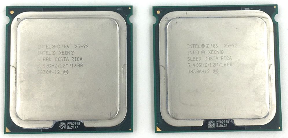
And if I do fry them $170 gets me the next (and final) step up on the performance scale for the 771 socket in the form of two Intel Xeon X5492 3.4GHz 12M 1600M Quad-Cores :D

Wohoo outdated technology prices!!!

 
Soldato
Joined
4 Dec 2015
Posts
3,221
Location
London
Nice design work mate, what are you using for it out of interest?

I love the idea of the digital read outs under each of the res stacks... The drain just needs to go at a low point but also if you think logically how it will drain from your bends and complex loop it might struggle (as my own did). Having it off the pump does work though mine was fine like that but you could have the T valve just above the inlet on the pump and out the back - you will have to man handle it around to different orientations to get it all out anyway.
 
Man of Honour
Joined
16 Mar 2005
Posts
8,057
Location
Clevedon , Bristol
Great renders, and you've obviously put a lot of planning into it.

2 small things;

Don't add red as the second loop, either go dual white or white and grey/silver - Mono-tone or semi mono tone works well.

The acrylic floor - love the idea with the temp readouts and listings, also love the cutouts where the tubing comes through. But the Intel Skulltrail logo does not fit , i would prefer you extend the 'venting slots' instead.

Unless you have been sponsored i don't like excess logos in a build. Clean and simple is far better.

Look forward to watching the build.
 
Associate
OP
Joined
29 Jun 2016
Posts
65
Nice design work mate, what are you using for it out of interest?

I use Sketchup for the modelling and a free program called Kerkythea for the renders. Great thing about Sketchup is the 3D warehouse where people have modeled a lot of the components to scale like the rads, waterblocks & fittings. Very accessible for first time users. The danger is its also easy to get carried away. Have completely blown the budget on this one!

Cheers for the pointers on the drain position. I was hoping off the pump would be the most sensible place. There is a generous gap between the rad and pumps. What I'll probably do is run a drain line to the rear of the case and out the back. I can then tip the whole thing onto its back edge for easy draining - probable even prop it up.
 
Associate
OP
Joined
29 Jun 2016
Posts
65
Great renders, and you've obviously put a lot of planning into it.

2 small things;

Don't add red as the second loop, either go dual white or white and grey/silver - Mono-tone or semi mono tone works well.

The acrylic floor - love the idea with the temp readouts and listings, also love the cutouts where the tubing comes through. But the Intel Skulltrail logo does not fit , i would prefer you extend the 'venting slots' instead.

Unless you have been sponsored i don't like excess logos in a build. Clean and simple is far better.

Look forward to watching the build.

Loop Colour
The red was just to differentiate the loops at design stage and for clarity in the exploded view. Had intended a single colour initially but the loop design has been updated and now would really benefit from two colours.

Still need to decide what they will be though. I have a real soft spot for UV reactive - even if it can look less 'classy'
On the other hand I have seen white and grey/silver loops and they do look fantastic.

Acrylic Floor
I know it won't be to everyones tastes but I was keen to incorporate the skulltrail logo somewhere in the case. Maybe it just needs to be smaller. I'm intending on laser cutting all the acrylic so details like the logo would only be lightly engraved - should be quite subtle.

After all, there needs to be something to identify it as a Skulltrail system!
I had intially considered the modern version of the logo but wanted to keep it original/semi retro:


Last edited:
Associate
OP
Joined
29 Jun 2016
Posts
65
Voltage Regulator Loop

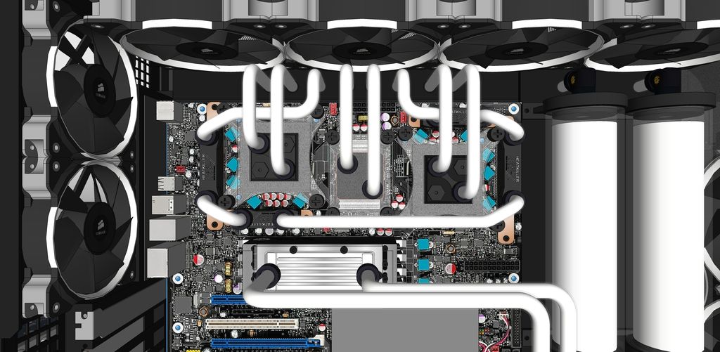
Universal MB blocks cut to the correct size. Have to pass VR loop under the CPU and NB loop. Think this is where a different colour in the second loop would really make the Voltage Regulator loop stand out.


Southbridge Waterblock

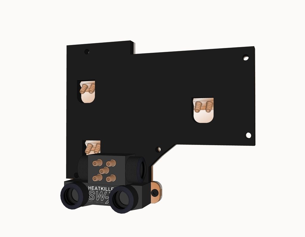
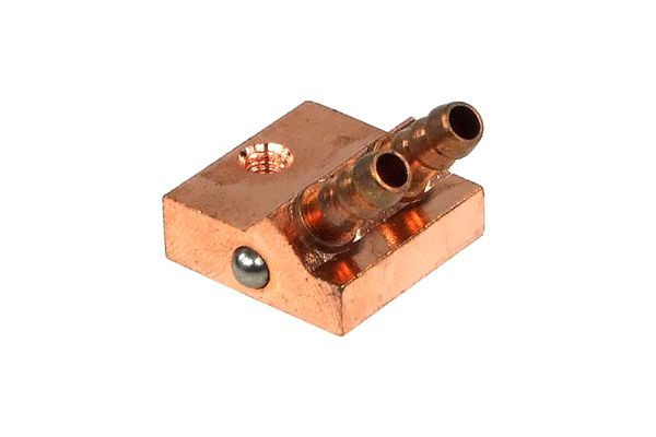
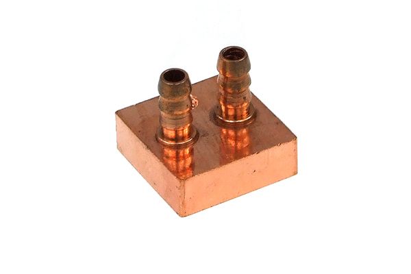
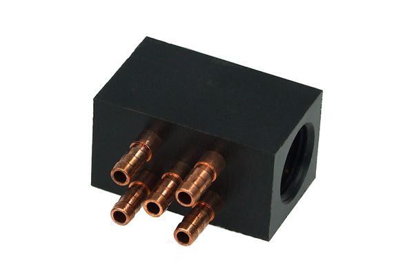
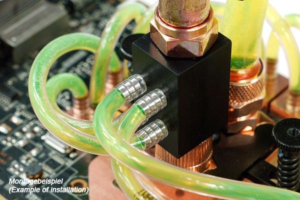
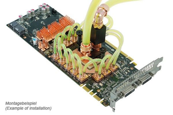
Machining a custom Southbridge Block is out of the question. So I'm working on a DIY heatsink utilising GPU Vram Mini Blocks. Super cheap. That coupled with another universal MB block should keep things cool - just need to sort the tube layout.


Mini Waterblocks and Splitters

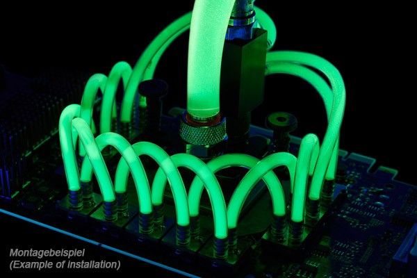
Getting very tempted by UV reactive!


Associate
OP
Joined
29 Jun 2016
Posts
65
Southbridge Waterblock Update

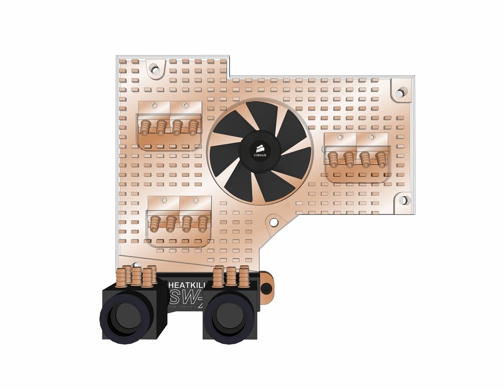
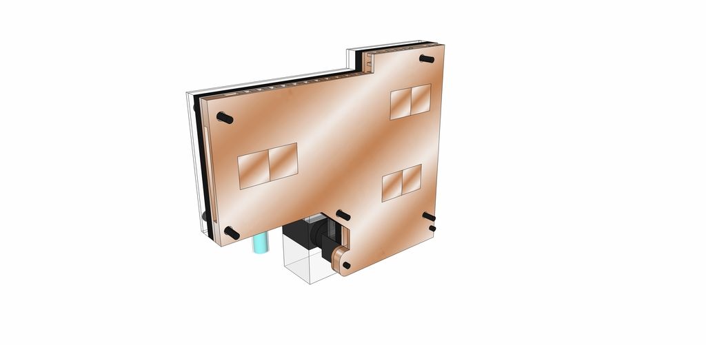
Minor rethink in the design - Planning to re-use the fan from the original Southbridge to help dissipate heat. Also will drastically increased the surface area of the block and should increase heat transfer. Although the mini blocks are perfectly sized for this application, the smaller diameter tubing will reduce flow. Have compensated by designing in two blocks per chip.

Although this looks complicated - most of the assembly is laser cut. I have access to a small engraving machine which should be just about capable of machining the copper base.
The benefit is the low cost of the components. Raw materials are cheap too and I'm hoping to do most of this with off-cuts. Critically, I'm not machining anything that has to hold pressure - The loop itself is independent of any fabrication work I have to do.

 
Associate
OP
Joined
29 Jun 2016
Posts
65
Final Southbridge Design

Moar loops.

Thinking about a white and silver colour scheme for the loops but still considering UV reactive. Have removed the second graphics card as buying a second STRIX 970 is waaay down the bottom of the list.


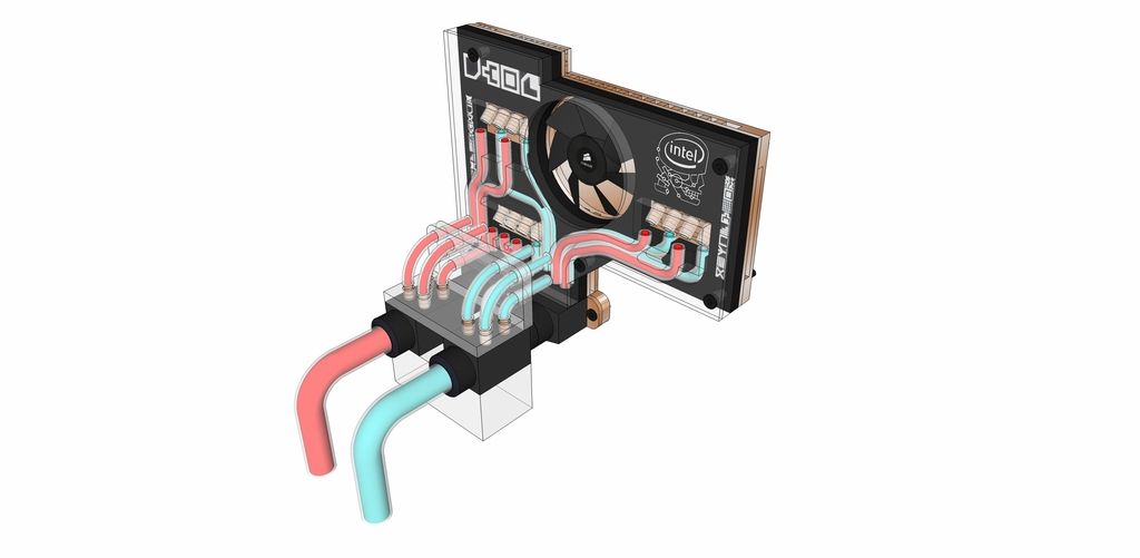
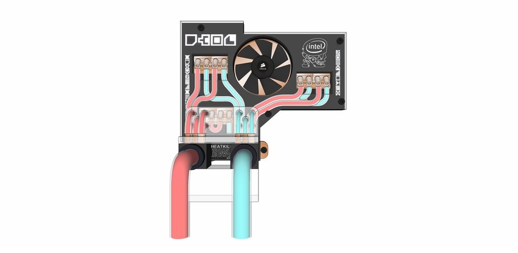
Im still in favor of showing off the mini loop in the southbridge - the images below looks a little confusing due to transparency. Red and blue is indicative only - just to differentiate between inlet and outlet.
I have not modelled the exact connecting junctions. I will revisit that when I do final renders sets. The main thing is confirming the loop routing.

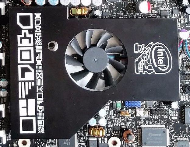
Im borrowing styling notes from the original Southbridge design:


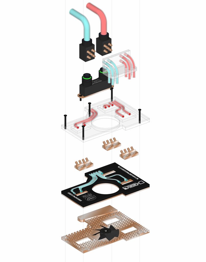
The Copper blocks will be soldered into place and then the whole combined plate area lapped and polished.


The exploded axo shows the relative simplicity in the design. The loops are sandwiched between two separate 5mm Acrylic sheets (one in clear and the other black)
The black 5mm layer is bonded to a copper plate which forms the lid for the fan/heatsink area below.

The clear 5mm layer is bonded to the clear lid which will hold everything together.


Should provide some fairly serious cooling :D
 
Associate
OP
Joined
29 Jun 2016
Posts
65
Update

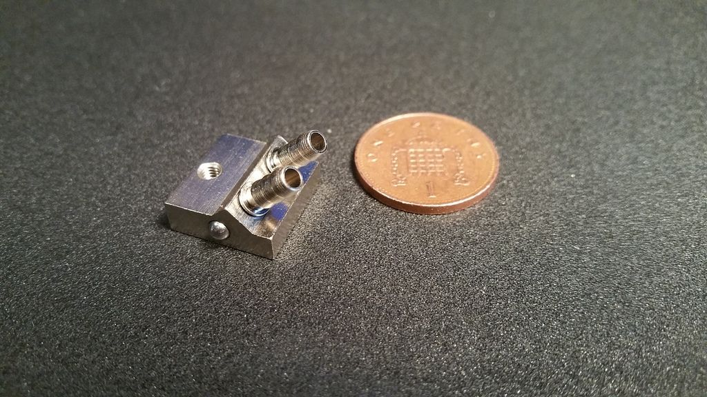
Mini Vram blocks arrived Today!

Blocks look fantastic! Penny for scale :D


Man, you like creating man made headaches for yourself !

Interested to see where this goes.

Having a major rethink of the case design at the moment. Looking at potentially making the design scale-able. As in, having an arrangement which would allow for easy installation of an an additional radiator should it be required without altering anything in the windowed section of the case. Plan requires a donor Silverstone TJ07 Case. Missed one for sale on gumtree for £40! Kicking myself now!

 
Last edited:
Associate
OP
Joined
29 Jun 2016
Posts
65
Design Update

Looking at a revision to the design which requires me to source another Siverstone TJ07 case.

Putting the current design on hold while I have a look around for one. Missed one on a well known trading site for £40!!! Kicking myself.
 
Last edited:
Soldato
Joined
31 Oct 2011
Posts
2,545
Location
Leyland
NEED HELP!Don't know if this circumvents the rules - mods please remove if it does.

I think it does, you're not allowed to talk about buying/selling from members outside the "members market"

Also, I think any link/mention of a "direct competitor" is against the rules, so I think the whole Aquatuning mention will have to go too.

Funny old place these forums.

Awesome looking build though, i will be watching closely for updates.
 
Associate
OP
Joined
29 Jun 2016
Posts
65
I think it does, you're not allowed to talk about buying/selling from members outside the "members market"

Also, I think any link/mention of a "direct competitor" is against the rules, so I think the whole Aquatuning mention will have to go too.

Funny old place these forums.

Awesome looking build though, i will be watching closely for updates.

Good call - have revised posts.
 
Associate
OP
Joined
29 Jun 2016
Posts
65
Design Revision

Looking for feedback/general thoughts.
Concern is that one 480x60mm, one 240x30mm and one 120x30mm rad will be insufficient for the over clock I'm hoping to achieve.

So bear in mind that this is still a little rough and ready - all the hard line routing still needs to be finished.

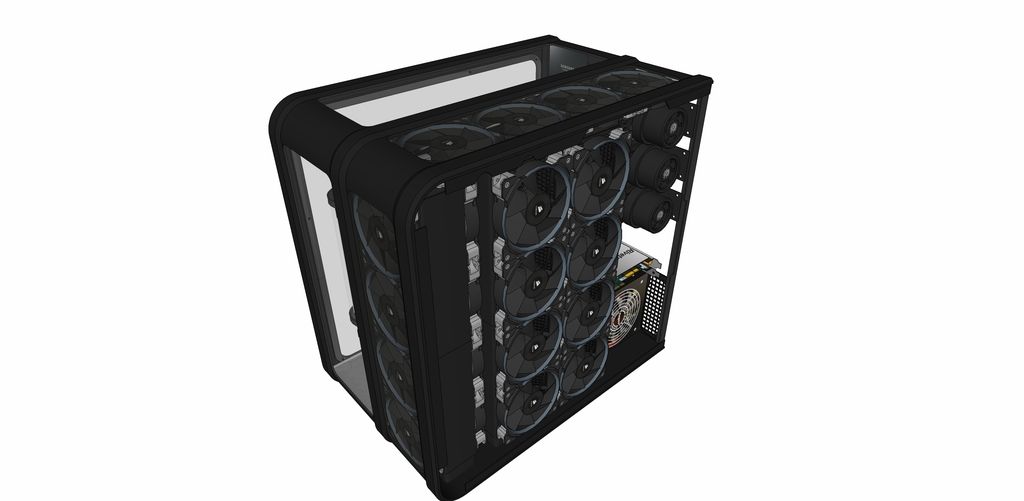
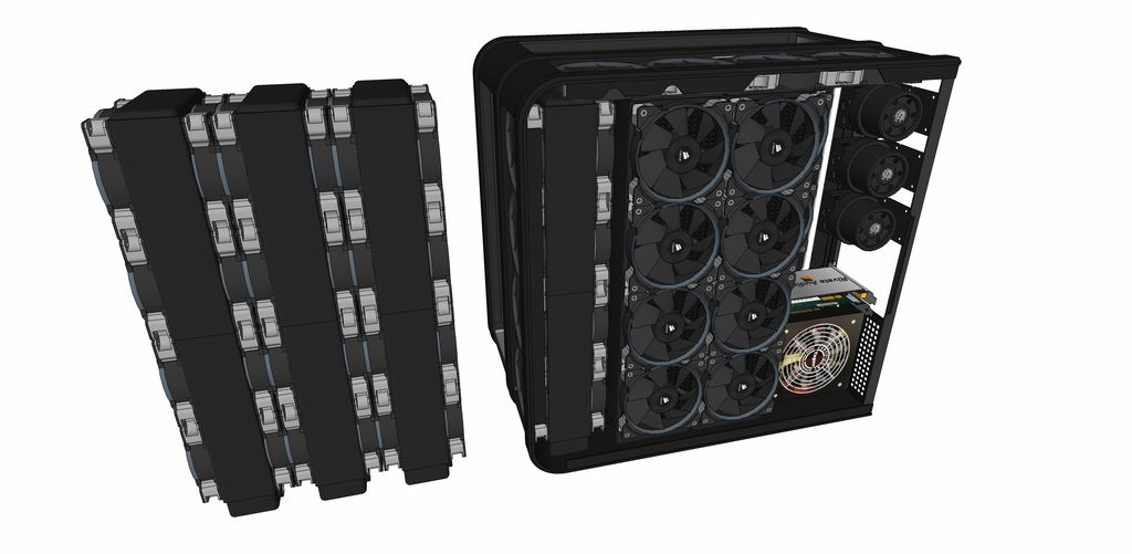
Design removes all radiators, pumps and fans to the side of the case. Shortened donor TJ07 chassis acts as housing. The main portion will then be glazed on three sides exposing the components.

Creates space for at least 3no. 480x60mm rads all in push/pull fan configuration. I'm not saying thats what's going in, just that there is space for at least that many components/ future expansion.

Other benefits:

1. PCI E extender allows graphic cars to be positioned in any location to better show them off (may be watercooling them)

2. More space for custom southbridge cooler (design has been refined again -more on that later)

3. Less attractive soundcard and WiFi card can be concealed in other side of case.

4. Space now for 3 loops - note extra reservoir.

5. Ain't no one got a TJO7 like this.

Just wasn't happy with the current design - starting to make too many compromises.

Looks weird now - give me a chance for some spit and polish to prove the concept.


Rad & Fan config


Have two possible configs for rad/ fan arrangement. Benefit to option on the right would be that all of the rads have a fresh air supply directly from outside.

Left side config would be more compact and has all fans working together. Can anyone tell me the benefit /downsides of both?

 
Back
Top Bottom