PARVUM APIS by JR23

Associate
Joined
25 Aug 2011
Posts
407
Location
CLASSIFIED
Main%252520banner.jpg


Hey guys! Yes i'm back with another build, but this one isn't for me, I have enough rigs for now, it's for my good friend TJ. He actually got me heavily into tech and PC's when we were growing up and has been enviously watching on my various exploits building insane watercooled rigs and working with Parvum. So now we are working together to build a completely new rig for him with some serious water cooling and pretty insane components for it's size.

I won't be photographing every baby step on this one, just giving a thorough overview of the progress and custom work taking place, as we want to get it completed quite swiftly when we both have the time to work on it.


Parvum Systems R1.0 360
Intel Haswell-E i7-5930K
EVGA X99 Micro
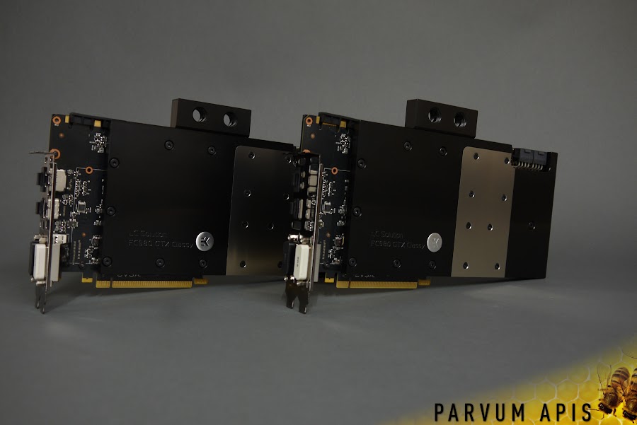
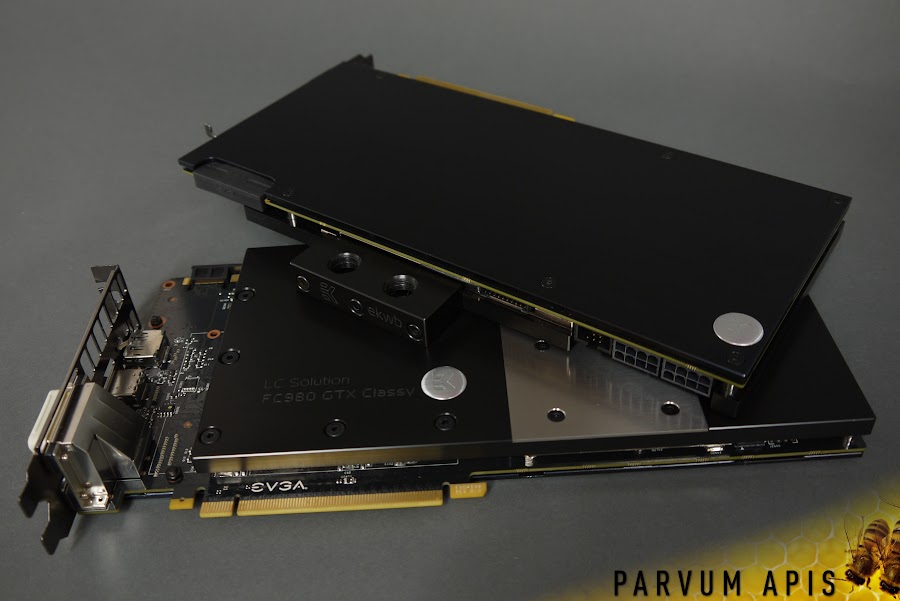
EVGA GTX 980 Classified x2
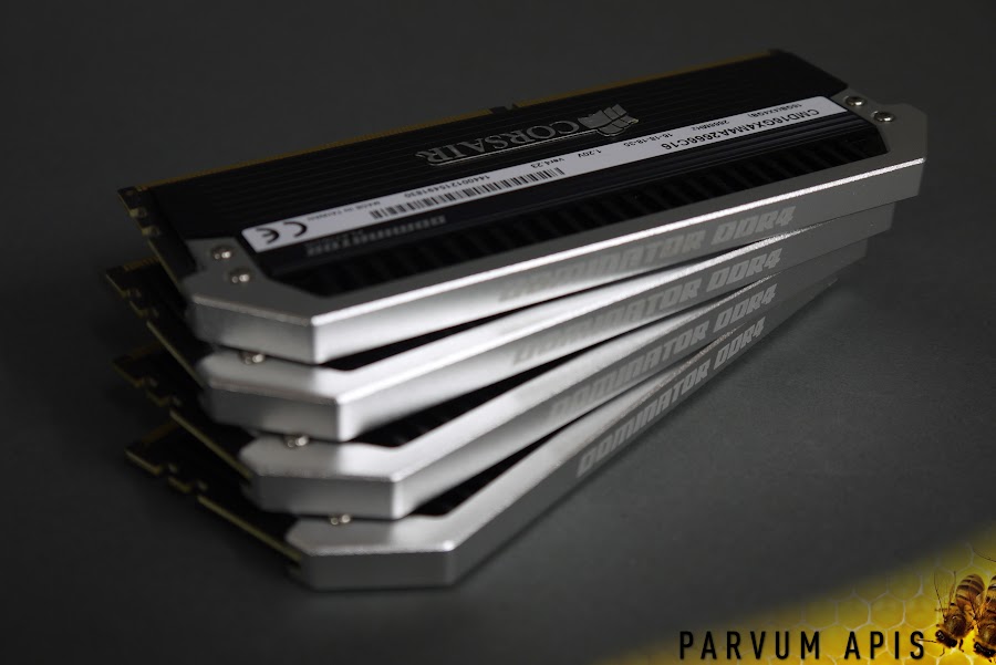
Corsair Dominator Platinum DDR4 4x4GB
Samsung 500GB 840 Evo

EK FC980 Classy Nickel/Acetal x2
EK Supremacy EVO Nickel/Acetal
EK D5 REVO Pump Top Acetal
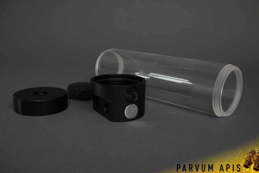
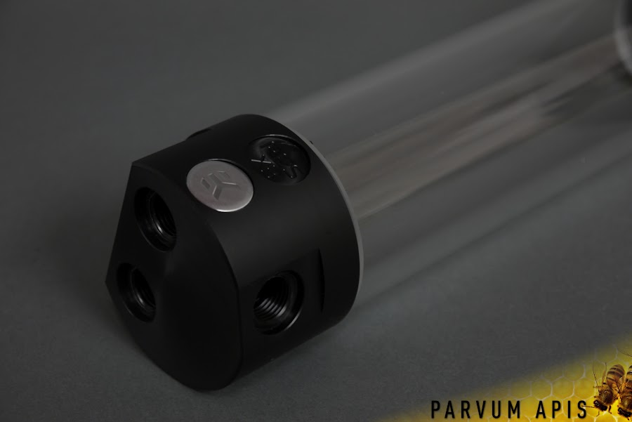
EK RES X3 250 Black Acetal
EK CoolStream PE 360 (Triple)
EK HD Adapter 10/12mm Black Nickel x28
Corsair SP120 Performance Edition PWM x8


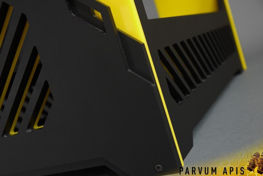
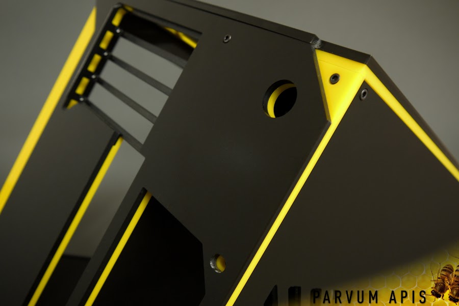
We spent a long time discussing the case, we established very early on that it had to be black and yellow which suited the neutral components very well. Everything had to be visible in an appropriate hierarchy making an inverted platform inevitable. The as of yet unreleased Parvum R1.0 seemed like a great starting point but despite only 3 existing in the world a more exclusive platform was demanded! Following a huge circle of deciding between an inverted S2.0 360 and an R1.0, the R1.0 360 was born.

1.jpg


2.jpg


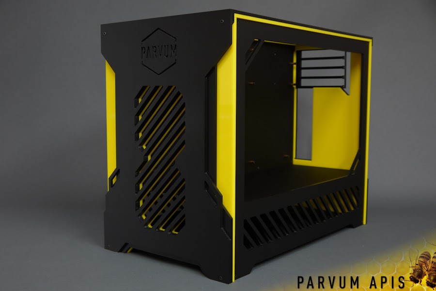
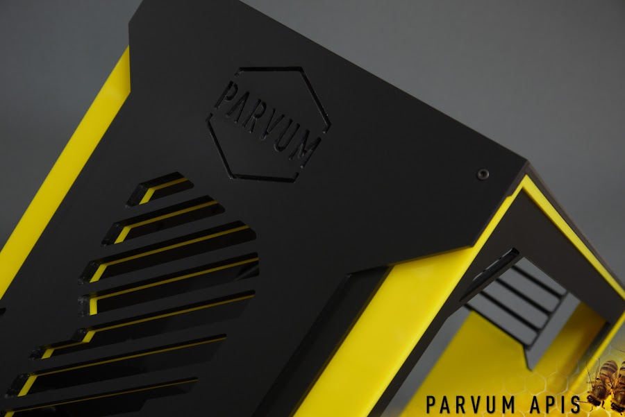
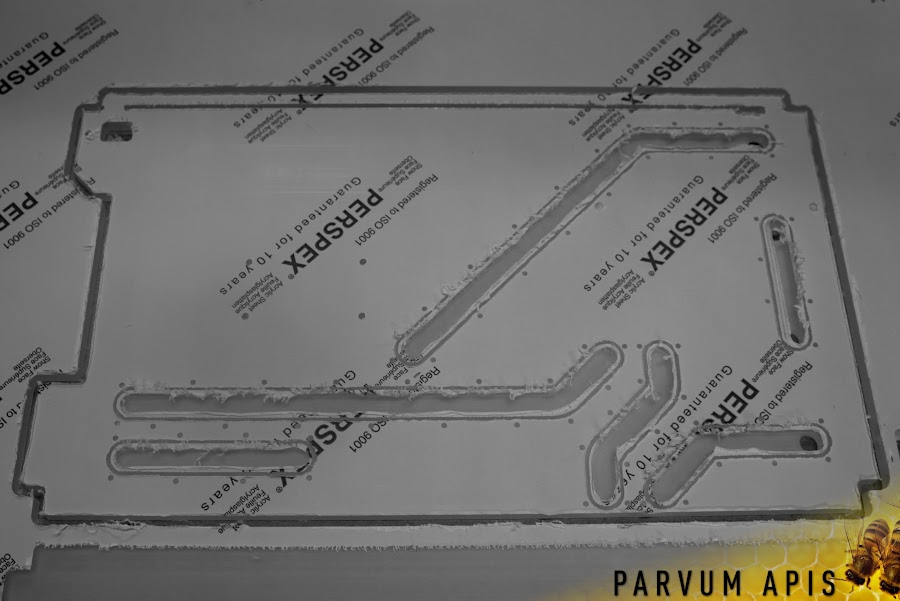
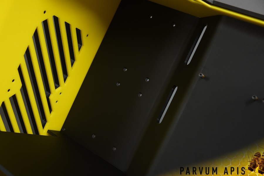
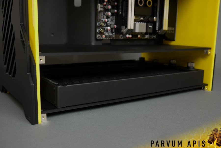
As a nod to the L1.0's subtle side vents which break up the pedestal we chose to also and a fine strip of slats to both side panels which hopefully will discretely reveal the radiators and fans lurking beneath them.

3.jpg


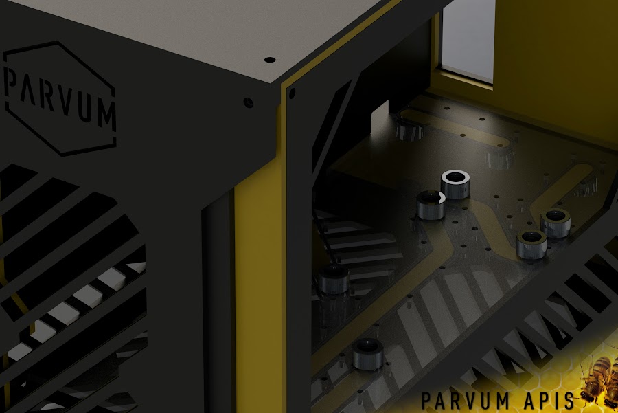
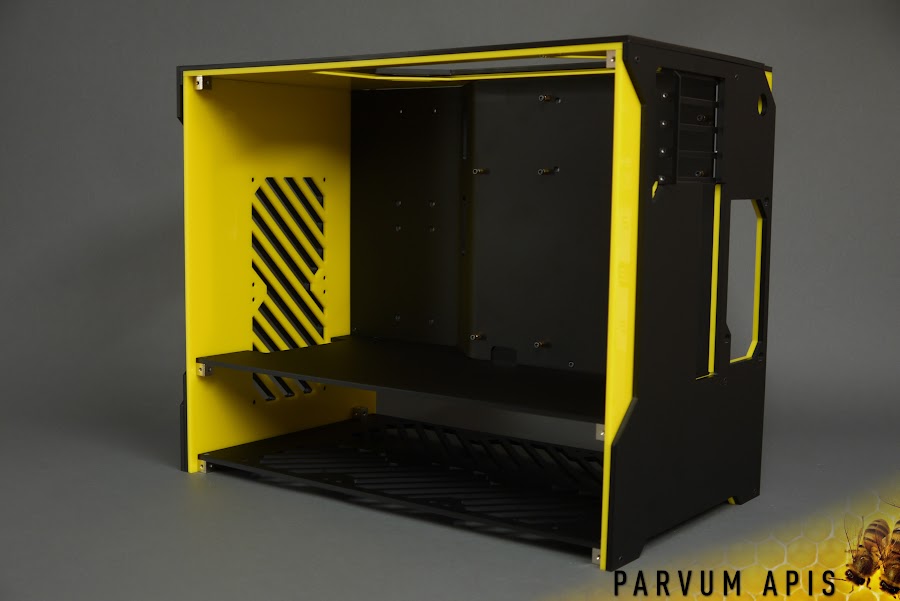
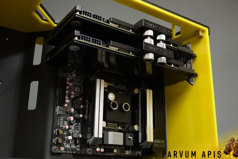
GPU window of course, why else go to the trouble of an invert.

4.jpg


5.jpg


6.jpg


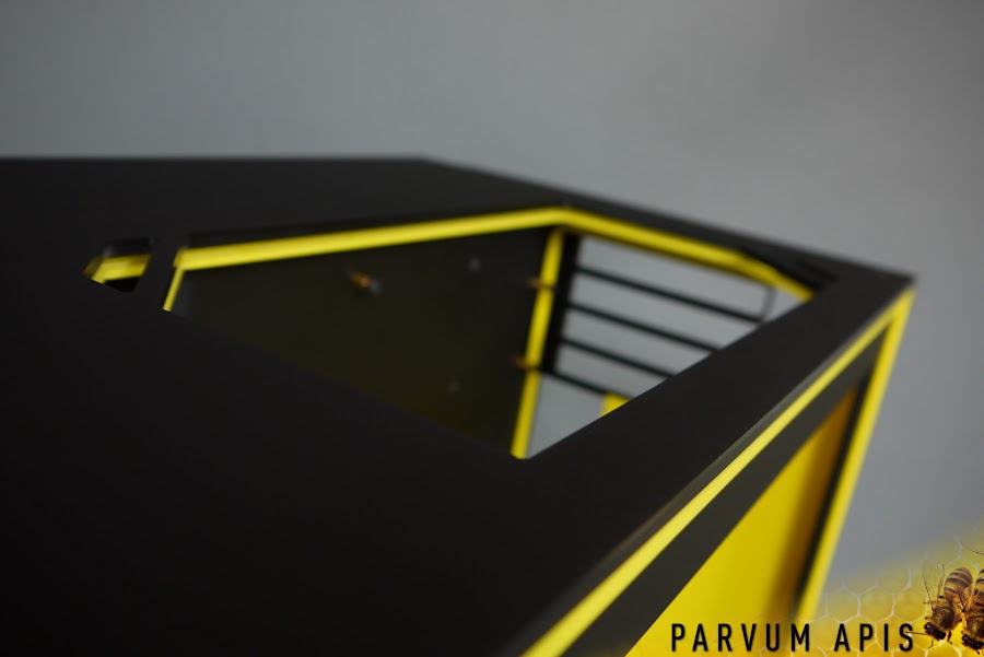
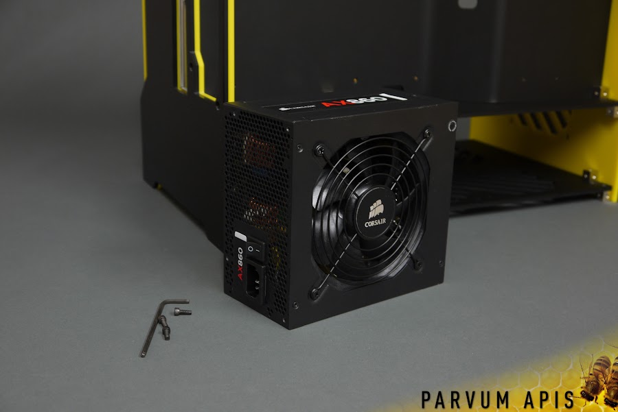
Cheeky rear power button, later in the build it will become apparent why it ended up here.

7.jpg


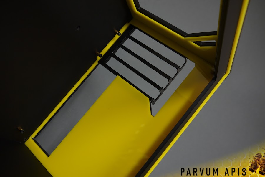
The relatively shallow height of the main chamber meant there wasn't room to take the conventional Parvum HDD bracket approach. Instead all of the drives will be mounted directly to the motherboard tray, not quite as modular but hopefully neater.

8.jpg


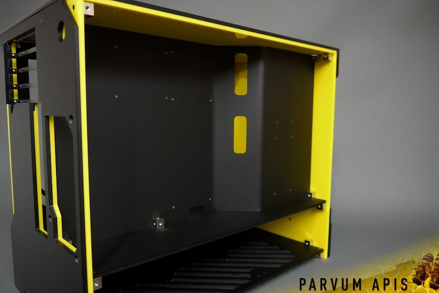
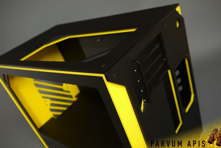
Finally what it's all about! It occurred to me a while ago that the S2.0 was the exact width of two radiators hence why the R1.0 was created, this takes that a little further by adding two 360mm radiators side-by-side. Quite unique for what is still a relatively compact mATX rig. I really love the wider aspect ratio it brings to the window leaving lots of room for pumps and reservoirs ahead of the graphics cards.

9.jpg


10.jpg


I'll be back very soon with the first test fitting then it's on to design the loop. :)

JR
 
Last edited:
Associate
OP
Joined
25 Aug 2011
Posts
407
Location
CLASSIFIED
Main%252520banner.jpg


Time for hardware, lots and lots of X99 goodness condensed into mATX form with added Classified, for a 475x275x387mm baby rig it's rather serious.

1.jpg


Naturally Clean CSQ Supremacy EVO to match the GPU's.

2.jpg


3.jpg


4.jpg


And a nice subtle set of DDR4 Dominator Platinums.

5.jpg


6.jpg


7.jpg


8.jpg


9.jpg


10.jpg


With the board sitting neatly in the case it's time for the GPU's. For 980's these are WIIIIDE.

11.jpg


12.jpg


13.jpg


14.jpg


How to install GPU's in a Parvum like a pro, who forgot to buy more M3 nuts, but still making life easier with the screws from behind.

15.jpg


Now that is Classy, GG Edvard.

16.jpg


17.jpg


Better make sure that a PSU fits nicely while we are at this early stage, we will most likely look for something a little more powerful but just had this to hand.

18.jpg


19.jpg


20.jpg


21.jpg


22.jpg


23.jpg


All things together are looking great so far, the GPU's look surprisingly big in the case but none the less they are 'inside' the case and hence onwards very shortly to the water cooling parts!

JR
 
Last edited:
Associate
OP
Joined
25 Aug 2011
Posts
407
Location
CLASSIFIED
Main%252520banner.jpg


Woo another update with some more lovely EK kit! Naturally a pair of 360's...

1.jpg


2.jpg


They fitted in perfectly not even leaving millimeters to spare.

3.jpg


4.jpg


We managed to scavenge an EK RES X3 400 and hence bought a 250 tube for it, this should be just the right height to fill out the main chamber now.

5.jpg


6.jpg


7.jpg


The first time i've seen a D5 REVO and it's actually quite a refreshing piece of design, not quite as clean as it's predecessor although certainly sophisticated and eye catching.

9.jpg


10.jpg


Things quickly found their natural place in the rig creating a nice hierarchy of parts.

11.jpg


12.jpg


13.jpg


14.jpg


15.jpg


A good full day of loop planning and CAD to do now and then some excellent CNC fun ^_^.

JR
 
Associate
OP
Joined
25 Aug 2011
Posts
407
Location
CLASSIFIED
Hey guys,

Just trying out some midplate layouts for APIS, the plate you are looking at from above will replace the midplate routing coolant channels around the case. The bottom 4 ports will drop down directly into the radiators and the remainder will come up into the various components. These both seemed to come naturally but i'm having difficulty deciding which I prefer so I thought I would ask you guys!

I like how the right one appears a little more chaotic and random, not taking the shortest route between the two radiators. However the tight symetry between the CPU and GPU ports on the left plan is really appealing. I will put it to TJ in the morning. Just incase it's a factor for any of you, the left layout would mean having the CPU block the traditional way up rather than inverted with the motherboard.

loop%252520plan.jpg


JR
 
Associate
Joined
10 Jul 2013
Posts
1,023
Location
Space
I would say the left if its going to be the cleanest if that's what I'm reading and looking at, also being slightly ocd it means the cpu block stays the right way hope that helps
 
Associate
OP
Joined
25 Aug 2011
Posts
407
Location
CLASSIFIED
Main%252520banner.jpg


Just a little preview of the midplate design, i'm off to Parvum HQ early in the morning hopefully to get this cut ready for assembly at the weekend.

1.jpg


2.jpg


JR
 
Associate
OP
Joined
25 Aug 2011
Posts
407
Location
CLASSIFIED
Main%252520banner.jpg


Today we got the pass through parts machined ready for assembly this weekend. Unfortunately with the CNC hunkered down in productivity mode there isn't too much visible acrylic decimation because of the foot which encompasses the tool. But without it Parvum HQ would slowly get buried in a sea of acrylic swarf.

1.jpg


2.jpg


You can just make out the tool drilling the screw holes to be tapped through the hole.

3.jpg


4.jpg


5.jpg


6.jpg


8.jpg


9.jpg


10.jpg


Tomorrow i'll be tapping all of the 1/4" BSP holes, making o-rings and sealing the part together then hopefully i'll get on to making some acrylic pipework. Tj will be around to help so hopefully it will be a productive weekend.

JR
 
Back
Top Bottom