

Associate
Now, I'm not sure if this is the right place to put this, but it is a project and it is related to PCs!
I will be calling on people's advice who know their electronics well or who work with PCB. For my GCSE Electronic Products course I am making a PC fan failure alarm, I know many computers have this built in but that doesn't really matter for what I'm doing!
Here's what I am looking to achieve:
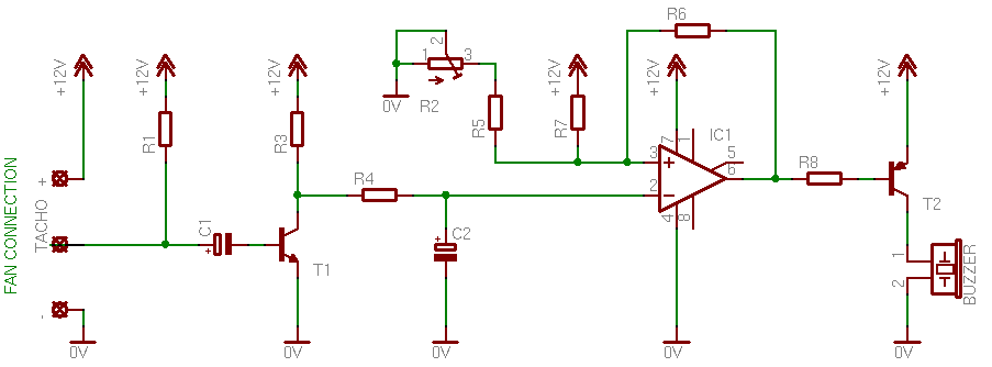
The simplest example of a circuit I could find was the one below which I will be basing my own circuit on, where the 741 comparator compares the voltage from the fan tacho line to the adjustable one coming via the potentiometer. Fairly simple stuff, except the fan outputs pulses rather than straight voltage, so it must be converted.
Full info: http://pcbheaven.com/circuitpages/PC_Fan_Failure_Alarm/
So I'm going to be needing some advice on this project. Firstly, the circuit relies on the fact the fan emits 2 pulses per rev- is this the standard for most fans? Secondly, can you see any issues with this circuit? I am going to get it to run from a single 12V rail rather than all those inputs used, which I do not see as a problem. As I am not allowed to run the circuit from a PSU, I will have to run it from a 12v battery or even a few 9v batteries, do you see this causing problems? I will be putting a Molex connector for the power rails, and then I can modify the other end of it to connect to a 12v battery, so it can be used with a computer PSU without any modification. Lastly, I am going to need it to attach to a PCI bracket. The first issue is finding a blank PCI bracket, so suggestions on where to get them would be appreciated, and secondly, actually attaching the thing! I was planning the drill about 4 holes along the front of the PCB then get some kind of tiny, 90* bracket and then screw it into the PCB and either screw or rivet it to the bracket.
Suggestions on how to overcome the problems, possible issues or improving the circuit would be appreciated.
I will be calling on people's advice who know their electronics well or who work with PCB. For my GCSE Electronic Products course I am making a PC fan failure alarm, I know many computers have this built in but that doesn't really matter for what I'm doing!
Here's what I am looking to achieve:
- A circuit that sets of a buzzer when a PC fan stops rotating or falls below an acceptable RPM
- The alarm should stop if the fan restarts
- It should be mounted to a PCI bracket
The simplest example of a circuit I could find was the one below which I will be basing my own circuit on, where the 741 comparator compares the voltage from the fan tacho line to the adjustable one coming via the potentiometer. Fairly simple stuff, except the fan outputs pulses rather than straight voltage, so it must be converted.
Full info: http://pcbheaven.com/circuitpages/PC_Fan_Failure_Alarm/
So I'm going to be needing some advice on this project. Firstly, the circuit relies on the fact the fan emits 2 pulses per rev- is this the standard for most fans? Secondly, can you see any issues with this circuit? I am going to get it to run from a single 12V rail rather than all those inputs used, which I do not see as a problem. As I am not allowed to run the circuit from a PSU, I will have to run it from a 12v battery or even a few 9v batteries, do you see this causing problems? I will be putting a Molex connector for the power rails, and then I can modify the other end of it to connect to a 12v battery, so it can be used with a computer PSU without any modification. Lastly, I am going to need it to attach to a PCI bracket. The first issue is finding a blank PCI bracket, so suggestions on where to get them would be appreciated, and secondly, actually attaching the thing! I was planning the drill about 4 holes along the front of the PCB then get some kind of tiny, 90* bracket and then screw it into the PCB and either screw or rivet it to the bracket.
Suggestions on how to overcome the problems, possible issues or improving the circuit would be appreciated.
 ). Now i dont know what components you have at your disposal, but i discovered that ADC is fairly common, but DAC is a little trickier to come by. Or at least in the world of chips. For example the chips i used did have ADC inputs, but only had digital outputs. This meant i couldn't vary the fan speed using voltage, and again i didnt really have the time (or PCB space) to work out the circuitry equivilent.
 )
)