Anglia Project

Soldato
Joined
13 Nov 2002
Posts
5,252
Location
Scotland
Cracking idea mate.

Im a huge fan of the engine, in fact, i prefer it over the BMW 3.0tt.

I was thinking the other day about a project where I could house the 6A13tt in something small and light, but youve beat me to it.

Cant wait to see it done
 
Soldato
OP
Joined
18 Oct 2002
Posts
8,016
With the engine & gearbox out and on the bench, it's time to do some of the bits that are easiest done whilst the engine isn't in the car.

When I removed the engine from the Galant, it was late one evening and I had limited tools, and I was unable to separate the gearbox and transfer box, or remove the torque converter! So, in the limited time I had, I decided the easiest thing was to remove the sump - so this needs to be sealed up properly again. Whilst the sump was off being cleaned, why not give it all a little squirt of paint to tidy it up a little?


The very bottom sump pan isn't in great condition, so I'll be looking for a replacement - hence why it's not been painted yet!

Also gave the exhaust bits a lick of high temperature paint to cover the bare welds.


During storage, the original 200SX gearbox got slightly waterlogged, and it's no longer particularly smooth. I managed to pick up another gearbox in good condition, doing a swap for the 200SX engine. This then needed modding as the original did to fit the starter motor and the water manifold to the engine. As it was originally modded in the car, the cuts weren't the neatest, so with the new gearbox on the bench, the modifications were made again, neater, and with a closer fit. It then had a good clean down, and a squirt with some paint as well.


Whilst the paint was drying, another small patch on the chassis, this one to cover over the original holes for the pedals, and cleaned up and slightly enlarged the holes cut out for access to the coolant pipes in the bulkhead, and for ease of fitting the alternator in the inner wing. These holes will have small ridges welded around them for screw-in panels at a later date.

 
Last edited:
Soldato
OP
Joined
18 Oct 2002
Posts
8,016
By moving the turbos from their natural home, the original oil and water feed & return pipes were no longer suitable. The water pipes have already been done, but the oil pipes required a bit of external help to ensure we had pipework suitable for the temperature and pressure of the oil. We contacted Hosequip who are based not far down the road, and talked to John who has made up some wonderful braided hoses.


With these in place, and the oil feed coming from the back of the block, we reassembled the rest of the engine and gearbox, and checked the fit of the starter motor with the new gearbox.


Before fitting this back into the car, we started to run the brake and clutch lines down the corner of the engine bay - access is a little tricky with the engine in place!


The new oil lines look great through the front.

We'd identified that the original gearbox mount we made was not quite correctly aligned, and was putting some twist into the mount - but it was done before the engine & gearbox were properly mounted, so it's not too surprising that it needed a small tweak. Once this was done, and the rubber mount sitting correctly, we attached the clutch slave cylinder to the side of the gearbox.


Taking some more of the stainless bumper bars, we continued working on the exhaust.


Using two corner pieces, and the centre section of the bit used for the bits directly off the turbos, we brought the pipes towards the gearbox, away from the steering column, and turned towards the back of the car.

]

From the side it looks a little low, but none of it is any lower than the front crossmember, which is the lowest point of the car - there's still plenty of ground clearance so speedbumps shouldn't be an issue I hope!
 
Last edited:
Soldato
Joined
11 Apr 2004
Posts
19,812
Wow, this is looking absolutely epic!

I can't believe the amount of work that's gone into building this thing. Can't wait to see it progress even further.

Oh, I think you should extend the exhaust pipes straight to the rear of the car. No boxes :D
 
Caporegime
Joined
19 Apr 2008
Posts
26,266
Location
Essex
Wouldn't it have been easier to spaceframe the front of the car out with a flip front rather than trying to wedge such a huge and unwieldy lump into the engine bay?
 
Soldato
OP
Joined
18 Oct 2002
Posts
8,016
Wouldn't it have been easier to spaceframe the front of the car out with a flip front rather than trying to wedge such a huge and unwieldy lump into the engine bay?

Easier - possibly, yes.

However - firstly I'd then have to cut away the original chassis stamps, and it'll require a full IVA test and a Q plate - which means I'll need to pay road tax!

Secondly, people who know these cars will know the size/shape of an original engine bay, and by having most of it in place still (albeit slightly modified in terms of shape to give a little extra clearance for engine movement) it's more of a "this is what we've been able to do in a standard chassis" - there was no *need* to cut the front away - if the original wings and front panel were in good condition, this modification could have been done utilising the original panelwork - we've just cut the front away because 1) it was rotten and 2) it's now slightly easier to lift the engine & gearbox out as one unit.


And yes, I'd quite like to hear it with the exhausts running straight to the back, don't think it'll be very neighbour friendly though! ;)
 
Soldato
Joined
11 Nov 2004
Posts
8,182
Location
Couvains, France
My first car was an Anglia 1200 Super with a 5 Bearing 1500GT full race spec engine, that was insanely fast, so much so I rolled it :o however, this thing will be a total monster, and that red-top would have been insane enough.

Can't wait to see the finished result.
 
Soldato
OP
Joined
18 Oct 2002
Posts
8,016
A bit more exhaustive work for this update. The next thing on the list was to continue with the exhaust. After getting down to the underneath of the car last time, we chopped off the excess, and welded on some flanges, and added a flexi section to allow engine movement, one with the mounting for an oxygen sensor, and a pair of nice straight bits of stainless pipe (Isuzu Trooper side step bars).

Also, whilst we were underneath the car, we've run two brake pipes from the master cylinder to the boot, where the brakes will be assisted by a pair of 1.9:1 remote brake servos. We also ran the fuel feed and return pipes from the engine bay to the boot, where we will put a petrol tank.


To finish off, another braided hose from Hosequip for the clutch, a couple of inches longer than the standard 200SX hose, and we were able to test out the clutch for the first time.


Unfortunately, a little hitch - the clutch is VERY heavy to use. However, whilst wandering around the Bromley Pageant of Motoring yesterday (where we went with my dad's 4 wheel drive Anglia) we found a 3:1 ratio remote brake servo, which should reduce the effort required to operate the clutch.

So, looks like it'll need yet another pipe running to the boot and back down the length of the car!
 
Last edited:
Soldato
OP
Joined
18 Oct 2002
Posts
8,016
After a small break to do some running repairs to the garage building, I'm back with another update.

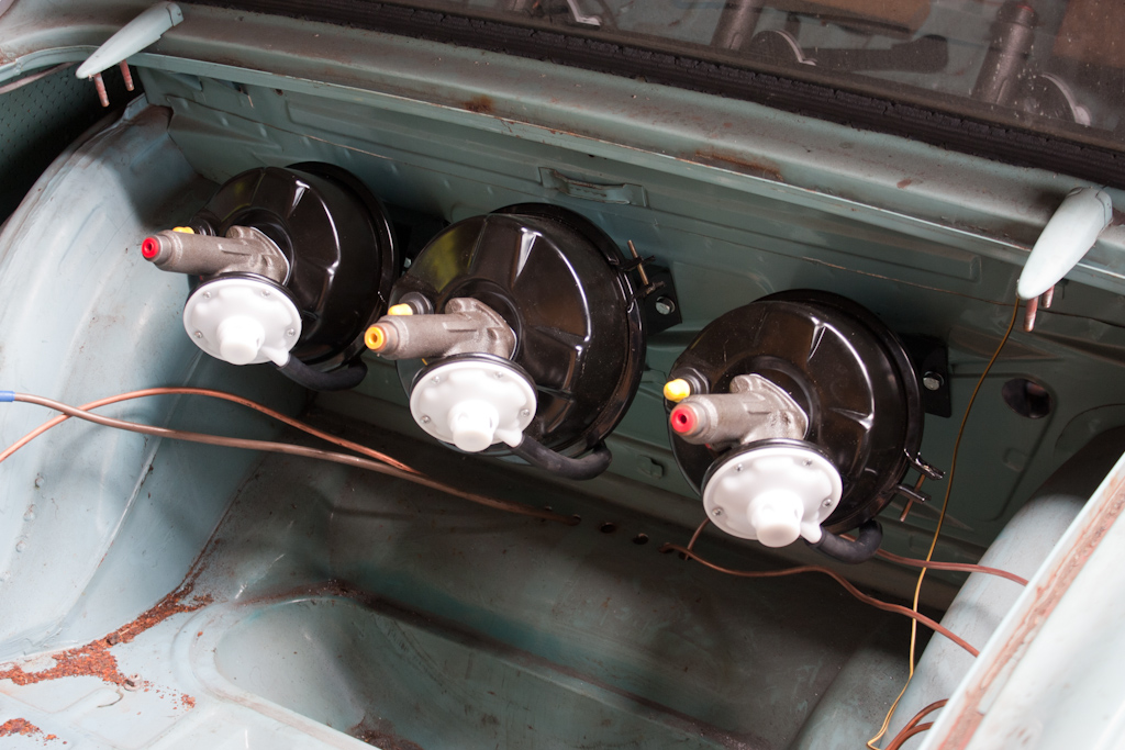
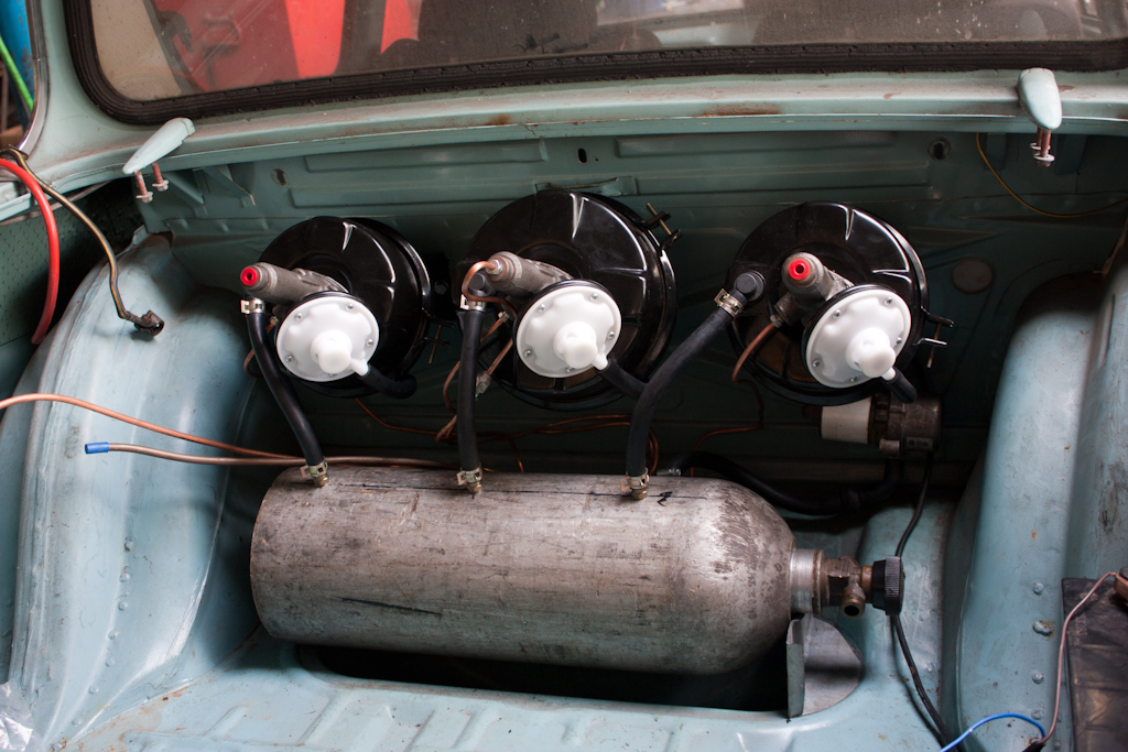
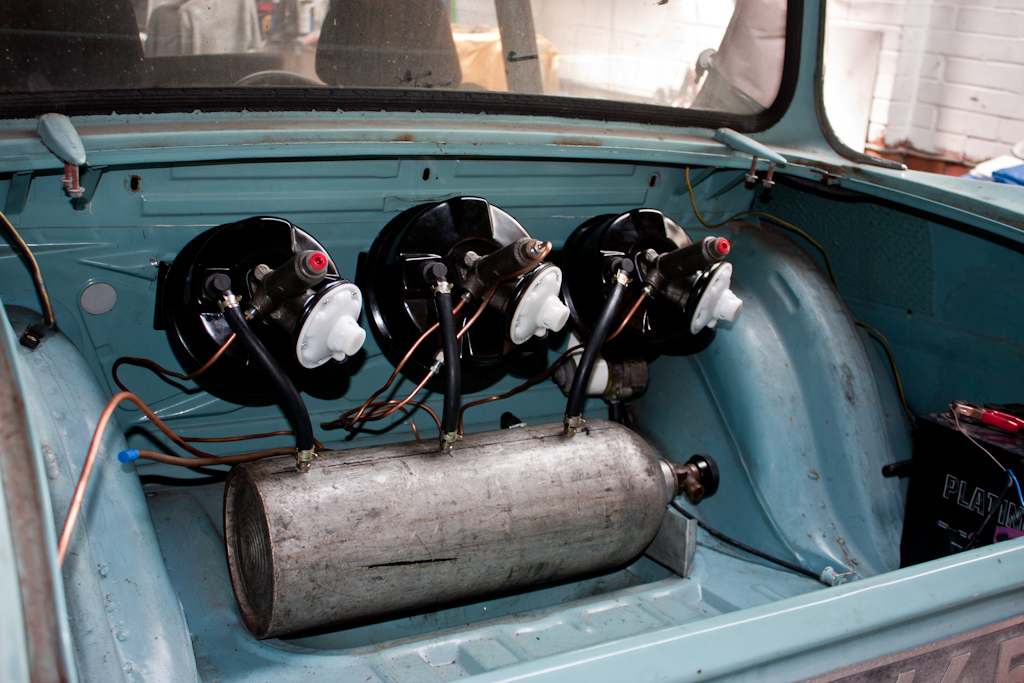
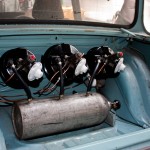
The first job was to unbox and mount the servos that were purchased last time - the only place for them is in the boot. Some minor modifications to the supplied mounting brackets, and they're all lined up at the front of the boot.


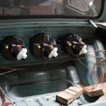
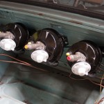
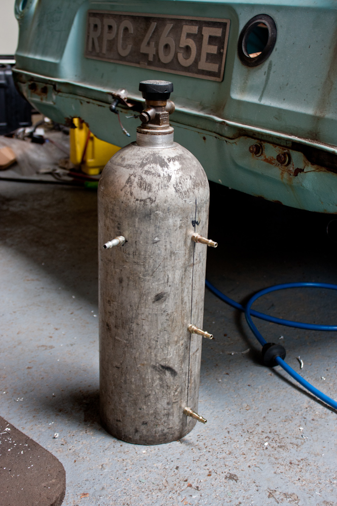
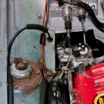
With 3 servos so far from the engine, and needing to be operated by vacuum, the usual route of providing vacuum from the inlet manifold on the engine would not have been ideal - especially with a turbo engine and requiring a servo for the clutch, enough vacuum can not be guaranteed. Therefore, we have decided to make use of an old CO2 welding bottle as a vacuum chamber to provide a large amount of vacuum to the 3 servos.


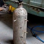
The bottle was fitted with some barbs to fit pipework to, and fitted into the boot of the car, and a mounting bracket was fabricated to support the end of the bottle where it tapers.


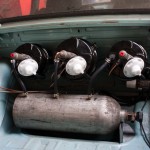
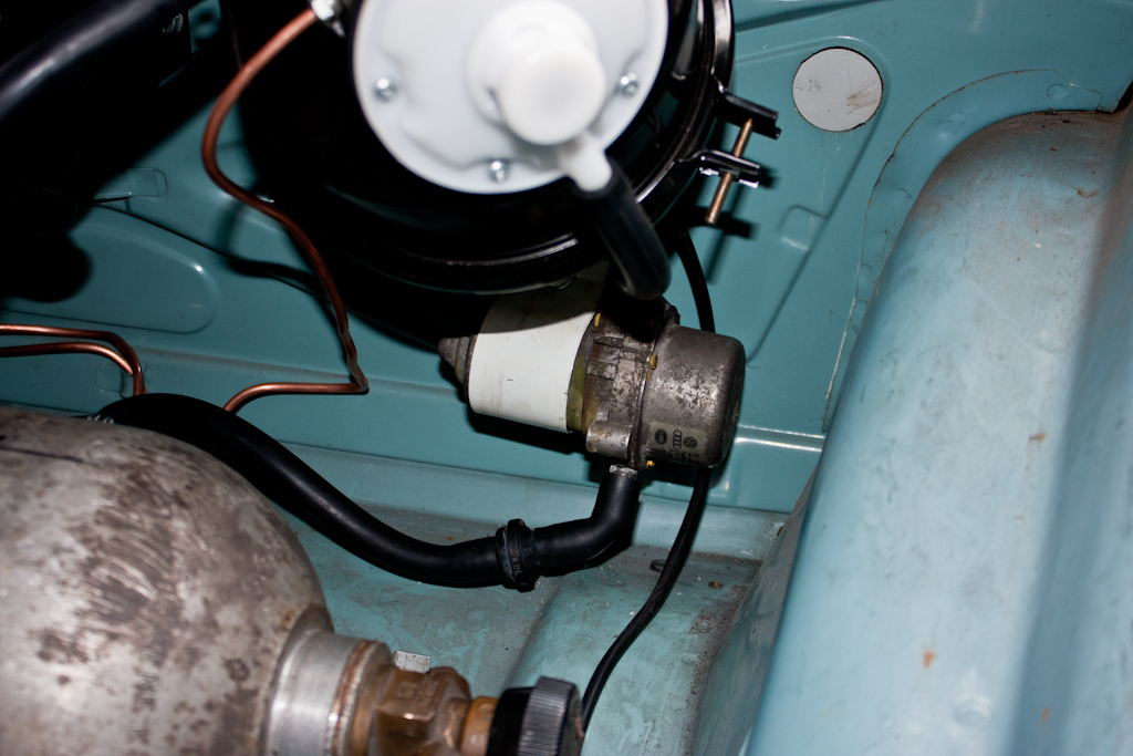
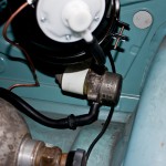
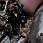
As I mentioned earlier, the vaccum will not be provided by the engine, so instead outside assistance is required to provide a vacuum. There are many vacuum pumps available, but most of these are driven directly from the engine, and the majority of these also require an oil supply - something that's not going to be easy. Therefore, we found an electric vaccum pump, usually fitted to various VAG cars (this one listed as being for an Audi TT), which requires purely a 12v electrical connection. A vibration-reducing mount was made using an old cotton-reel style rubber mount, and it was plumbed up to the vacuum chamber.


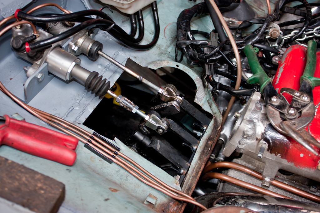
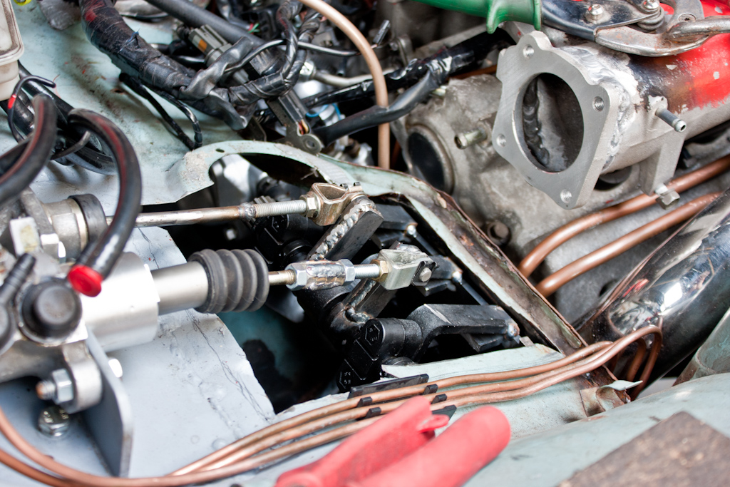
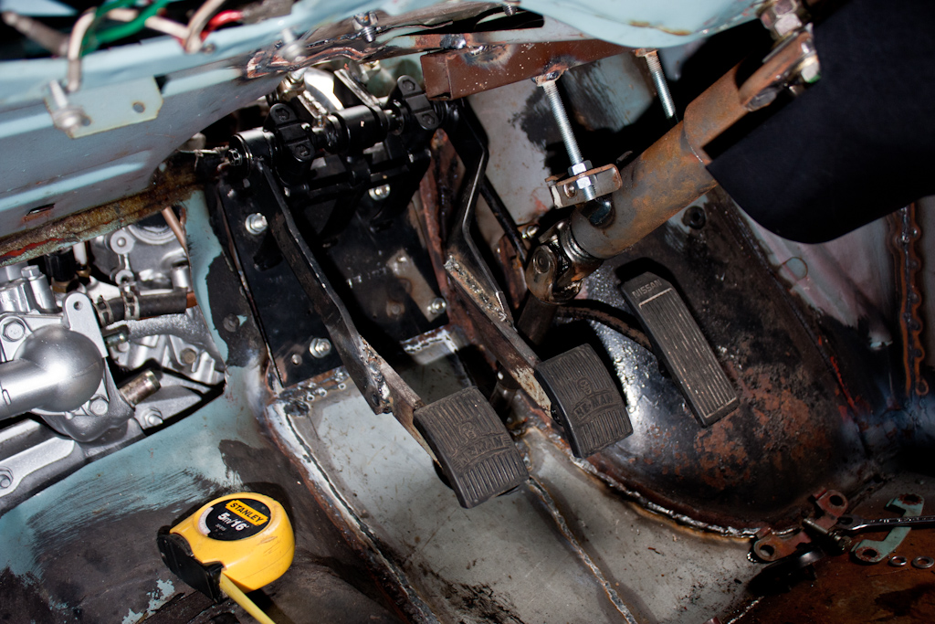
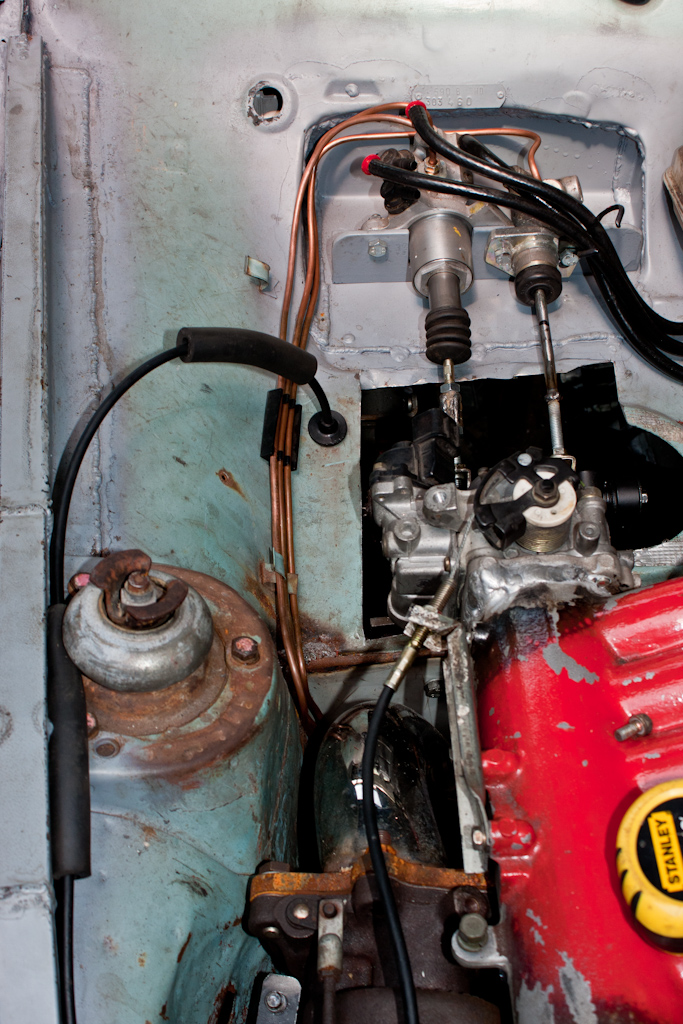
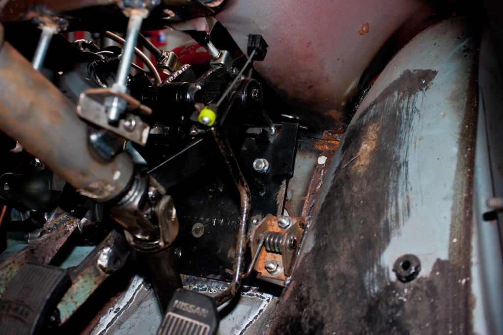
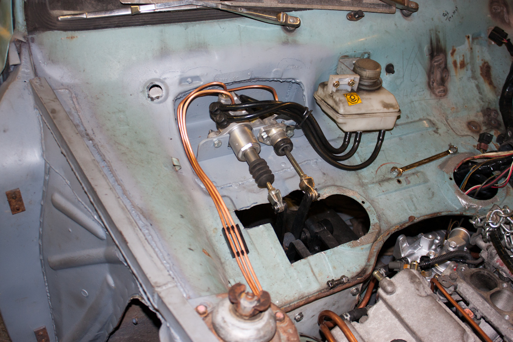
Applying 12v power to the vacuum pump until the chamber was "full" (or should that be empty?) of vacuum - it was time to test the clutch out. As predicted, this greatly reduced the effort required to operate the clutch, but it still it was not enough to make it comfortable to use - I want this to be a car that's not a chore to drive, and to have a modern feel to it. Therefore, to aid the servo assistance, we also adjusted the pedals slightly to further improve the levering force available from the pedal to reduce effort. The arms that operate the master cylinders was shortened, and the operating arms inside were lengthened slightly.


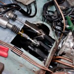
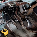
The combination of adjustments to the pedals, and the servos, has made the clutch operation now akin to a modern car - and I currently also only have a standard FTO clutch cover fitted - which may need to be uprated to one with higher clamping force to cope with putting down the 50% extra power over and above what a standard FTO clutch is designed for - this will add more resistance to the clutch system - and the assistance of the servo is definitely still required.

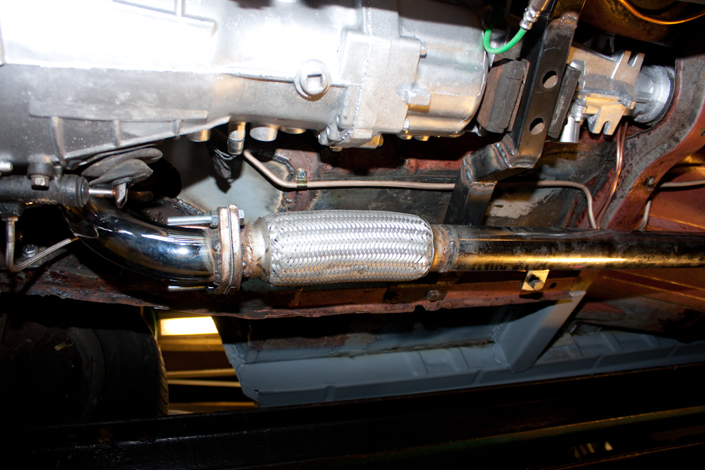
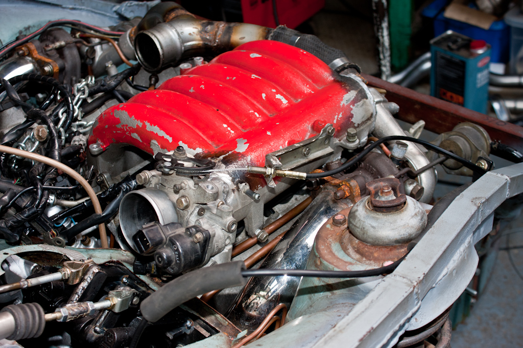
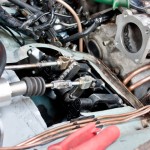
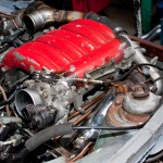
Now that the clutch and brake pedals were sorted, why not finish off the trio, with a new throttle cable hooked up, and a custom bracket made to attach it to the inlet manifold at the required angle to match with the adjusted throttle body location.

 
Last edited:
Soldato
OP
Joined
18 Oct 2002
Posts
8,016
The timing of this update is quite apt, having just received an email from Old Skool Ford forum listing their Favourite Projects, and included in the list is my little project! So, a huge thanks to the staff at OSF for the shout in their mass email!


It starts with a quick trip to collect some shiny bits for a good price, and to try to squeeze it into the back of a Fiesta because I forgot to pick up the hacksaw I placed in the hallway the previous night before leaving - which in itself was quite a feat of engineering! ;)


Having successfully collected the exhaust, which was previously fitted to a VR-4, the backboxes were chopped from the pipework, and lifted into place to measure up and see what it would look like with the 5" exit... the answer... a little stupid, especially on such a small car! No pic, unfortunately!

So, the outlets were also chopped off, and the boxes were lifted into place to measure up for the other pipework.

The exhaust bits already on the car were marked, cut, and adjusted to follow the line of the floor better, and in preperation for adding of the next parts.


I also purchased some 2.5" stainless over-axle exhaust sections, as they were available cheaper than making our own sections or buying various angled bits and welding together ourselves. These were fitted to the backboxes, and some brackets were made and welded to the chassis to support via some new exhaust rubbers.


Moving onto tailpipes, and we again utilised some offcuts from a section that has provided other parts of the exhaust, which was the enclosed ends of the bumper bar which forms the turbo elbows. The rear valance was roughly chopped to accomodate the second tailpipe, and they were fitted.


The enclosed bits were removed to give a pair of downdraught tailpipes - and hopefully nicely subtle!

 
Last edited:
Back
Top Bottom