Something unusual for the HiFi forum 
After watching the Repair Shop, it turns out that the mother-in-law had an old Phillips radio and record player console sitting rotting in a corner unused.
Original photo:
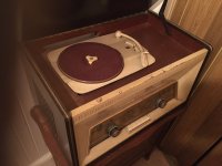
So I've just got this back home and I've had the chance to walk through the entire thing - I checked previously when over in France and it 'works' (after checking the caps for leakage etc).
The insides all work by vacuum-tubes (before transistors and microchips) and the entire layout of the circuit is 'point-to-point' as was the norm before the invention of PCB boards.
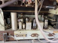
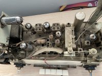
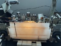
Here you can see some of the glass tubes, some of metal canisters shielding the variable tuning coils, the power transformer, the cylindrical main metal can filter cap on the left, and the underside of the record deck at the top.
The speakers at the sides just out of view.
The schematic is pretty simple but complex:

(Source: https://www.doctsf.com/radiola-ra-498-a-am-fm/f2891?PHPSESSID=1fedcbec22395a39394a363799fbc044 )
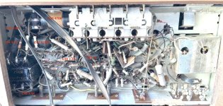
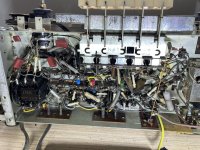
Now look at the point-to-point wiring:
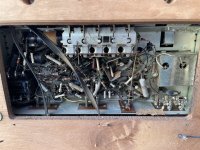
So to make this more fun, tubes run at high voltage low current.. So in comes 220Vac from the mains, it goes through the transformer and power supply to provide 275Vdc and a few other voltages. So this isn't 5Vdc stick a multi-meter in.
The black cylinders are pitch-enclosed capacitors. The small ceramic tubes aren't wire wound resistors but "dogbone" capacitors.
Sofar:
* checked the chassis reference status - this is floating but can be grounded (important to understand later).
* checked the tubes for damage and vacuum loss (destroys the tube) - all good.
* checked all the caps for leakage - no leakage with low voltage multi-meter.
* checked the majority of the resistors for drift - no issues, they all are within tolerances (although two are close to the edge).
* cleaned the dust as not to be a fire risk.
* Checked the power cord etc
* checked AM bands - all good, receiving and audio
* checked FM bands - all good, receiving and audio
* checked the oscillator and the wave frequencies seem clean.
Now to the issues. It's 65 years old. It will have issues. I have already cleaned up the 20-40 years of tobacco and nicotine grime uke:
uke:
* Power supply is 220Vac - this is regular thing, the modern wall power is 238Vac (France) and 245Vac (here at home). The issue is that the power supply to the internal components is relative to the input power - so 238Vac is just at the top of the operating range of the tube heaters (ie about 6.8Vdc for the 6.3Vdc heaters) so trying to plug this in here in the UK at 245Vac this would be over 7Vdc to the heaters which would damage them. This means I need to reduce the power - the efficient way is to use a step down transformer but the cheaper way is to use a resistor to drop the voltage by 25V so it's closer to the 220Vac that the power supply is expecting.
* Electrolytic caps are known to die over time, they have a limited shelf and operating life. However the black patch caps are known to be very good and still in spec, the tin cap used in the power supply tests correctly to block the power but it's usual practice to not risk it leaking DC voltage as that would cause a power short to the mains transformer *bang*!.
So a 500V 50uf+50uf dual section cap will replace the old original 1959 tin cap out of safety. I'll investigate if I can replace the tin cap internals with the modern cap or replace the cap completely.
* All the tubes are original Phillips Made in Holland. Neat but given they have been in service for 65 years (with a good 20 years "used as you use the TV now"), I would suspect they're a little tired. Although the main tubes seem fine - the magic eye tube clearly is very weak (just visible) and the internal backlight bulb for the tuning display is dead. So I will order a new magic eye tube and a back light display bulb (neon IIRC). I will wait until I have the power supply sorted to check the tubes in operation now I have the entire unit at home.
The AM/FM radio works nicely and given a strong station it will play loud and clear as to does the rubbing the stylus so the tubes still work. I did check the strength of the oscillator and that seems strong enough without any undue noise etc:
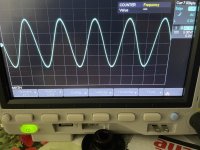
* The FM dial is misaligned and doesn't do a full sweep of the display. So that needs a physical alignment and possibly both AM and FM could do with a frequency generator setup and the tuning screws aligned - there's still factory compound on the coils!
I suspect that the two resistors that are part of the beat detection for the magic eye are also possible replacement candidates - they're in spec but merely as they measure at the edge of the 5% tolerance.
* The stylus is toast. It makes noise when prodded but I suspect it's had a hard life (there's a score mark on the plastic inline with the stylus arc!). As the cartridge is a high output (170mV) crystal output it could prove difficult to find a replacement - especially given the arm/cartridge design is mid 1960s and rotates to allow playing of normal and microgroove records. The cartridge is meant to have two stylus?! Not sure but I will investigate if there's a compatible Phillips quick change cartridge that will fit the geometry etc.
The record platter spins (direct drive via rubber roller) with mechanical adjustment of the speed.
So this is my concern at the moment as it may not be possible to source a cartridge or replacement. A minor modification could be made to allow attachment of an external photo pre-stage (probably an external transformer and connection to an external record deck). Either way (a) the record player isn't of today's audiophile standards, and (b) the console is mono only not stereo!
The alternative adjustment is to make a line in- then adapt the line in to 170mV or simply direct feed into the amplifier tubes direct.
* Wood paint/varnish - this is flaking and needs some attention to look similar to the existing patina.
If it was a stereo rather than two mono speakers, it would be a good candidate for some further investment/modding but think stabilising it and if I can find a record cart that will be good enough..

After watching the Repair Shop, it turns out that the mother-in-law had an old Phillips radio and record player console sitting rotting in a corner unused.
Original photo:

So I've just got this back home and I've had the chance to walk through the entire thing - I checked previously when over in France and it 'works' (after checking the caps for leakage etc).
The insides all work by vacuum-tubes (before transistors and microchips) and the entire layout of the circuit is 'point-to-point' as was the norm before the invention of PCB boards.

Here you can see some of the glass tubes, some of metal canisters shielding the variable tuning coils, the power transformer, the cylindrical main metal can filter cap on the left, and the underside of the record deck at the top.
The speakers at the sides just out of view.
The schematic is pretty simple but complex:
(Source: https://www.doctsf.com/radiola-ra-498-a-am-fm/f2891?PHPSESSID=1fedcbec22395a39394a363799fbc044 )
Now look at the point-to-point wiring:

So to make this more fun, tubes run at high voltage low current.. So in comes 220Vac from the mains, it goes through the transformer and power supply to provide 275Vdc and a few other voltages. So this isn't 5Vdc stick a multi-meter in.
The black cylinders are pitch-enclosed capacitors. The small ceramic tubes aren't wire wound resistors but "dogbone" capacitors.
Sofar:
* checked the chassis reference status - this is floating but can be grounded (important to understand later).
* checked the tubes for damage and vacuum loss (destroys the tube) - all good.
* checked all the caps for leakage - no leakage with low voltage multi-meter.
* checked the majority of the resistors for drift - no issues, they all are within tolerances (although two are close to the edge).
* cleaned the dust as not to be a fire risk.
* Checked the power cord etc
* checked AM bands - all good, receiving and audio
* checked FM bands - all good, receiving and audio
* checked the oscillator and the wave frequencies seem clean.
Now to the issues. It's 65 years old. It will have issues. I have already cleaned up the 20-40 years of tobacco and nicotine grime
 uke:
uke:* Power supply is 220Vac - this is regular thing, the modern wall power is 238Vac (France) and 245Vac (here at home). The issue is that the power supply to the internal components is relative to the input power - so 238Vac is just at the top of the operating range of the tube heaters (ie about 6.8Vdc for the 6.3Vdc heaters) so trying to plug this in here in the UK at 245Vac this would be over 7Vdc to the heaters which would damage them. This means I need to reduce the power - the efficient way is to use a step down transformer but the cheaper way is to use a resistor to drop the voltage by 25V so it's closer to the 220Vac that the power supply is expecting.
* Electrolytic caps are known to die over time, they have a limited shelf and operating life. However the black patch caps are known to be very good and still in spec, the tin cap used in the power supply tests correctly to block the power but it's usual practice to not risk it leaking DC voltage as that would cause a power short to the mains transformer *bang*!.
So a 500V 50uf+50uf dual section cap will replace the old original 1959 tin cap out of safety. I'll investigate if I can replace the tin cap internals with the modern cap or replace the cap completely.
* All the tubes are original Phillips Made in Holland. Neat but given they have been in service for 65 years (with a good 20 years "used as you use the TV now"), I would suspect they're a little tired. Although the main tubes seem fine - the magic eye tube clearly is very weak (just visible) and the internal backlight bulb for the tuning display is dead. So I will order a new magic eye tube and a back light display bulb (neon IIRC). I will wait until I have the power supply sorted to check the tubes in operation now I have the entire unit at home.
The AM/FM radio works nicely and given a strong station it will play loud and clear as to does the rubbing the stylus so the tubes still work. I did check the strength of the oscillator and that seems strong enough without any undue noise etc:

* The FM dial is misaligned and doesn't do a full sweep of the display. So that needs a physical alignment and possibly both AM and FM could do with a frequency generator setup and the tuning screws aligned - there's still factory compound on the coils!
I suspect that the two resistors that are part of the beat detection for the magic eye are also possible replacement candidates - they're in spec but merely as they measure at the edge of the 5% tolerance.
* The stylus is toast. It makes noise when prodded but I suspect it's had a hard life (there's a score mark on the plastic inline with the stylus arc!). As the cartridge is a high output (170mV) crystal output it could prove difficult to find a replacement - especially given the arm/cartridge design is mid 1960s and rotates to allow playing of normal and microgroove records. The cartridge is meant to have two stylus?! Not sure but I will investigate if there's a compatible Phillips quick change cartridge that will fit the geometry etc.
The record platter spins (direct drive via rubber roller) with mechanical adjustment of the speed.
So this is my concern at the moment as it may not be possible to source a cartridge or replacement. A minor modification could be made to allow attachment of an external photo pre-stage (probably an external transformer and connection to an external record deck). Either way (a) the record player isn't of today's audiophile standards, and (b) the console is mono only not stereo!
The alternative adjustment is to make a line in- then adapt the line in to 170mV or simply direct feed into the amplifier tubes direct.
* Wood paint/varnish - this is flaking and needs some attention to look similar to the existing patina.
If it was a stereo rather than two mono speakers, it would be a good candidate for some further investment/modding but think stabilising it and if I can find a record cart that will be good enough..
Last edited:


 but yep that a nice setup!
