A lot of this update is faff.
Cat decided not to supervise.
 20220723_105151_HDR
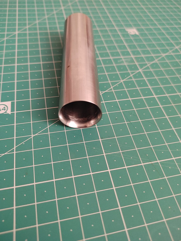
A 25mm outer diameter steel pipe...

A sharpened 25mm OD pipe for stamping holes in the veneer for the copper ports.
 20220707_220842_HDR
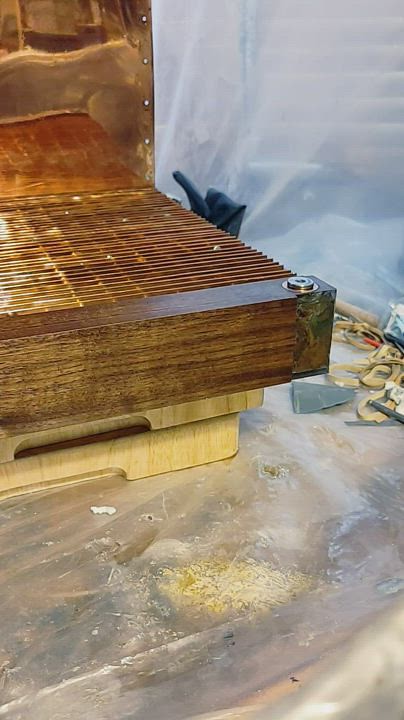
Gives a nice tight fit (video):
 20220706_195153
I recast more resin on the top pipe manifold... Trying to get it so I can have this veneered manifold sit flush with the aluminium frame...
Blurry photo with cast resin on the top manifold up to the edge of the aluminium frame (if you squint hard enough it sort of looks like this).
 20220707_225905_HDR
 20220707_225934_HDR
And some sanding with the sanding guide/frame to get nice sharp edges - snowstorm:
 20220711_224904_HDR
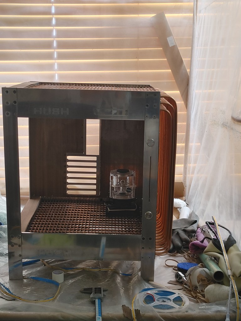
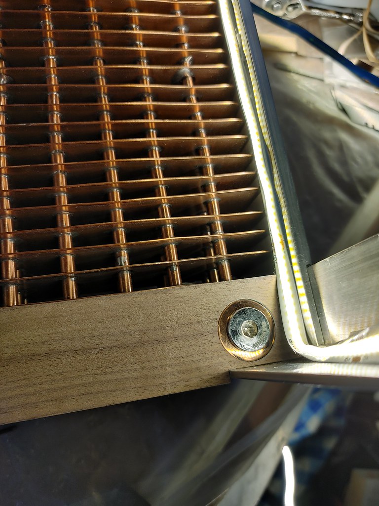
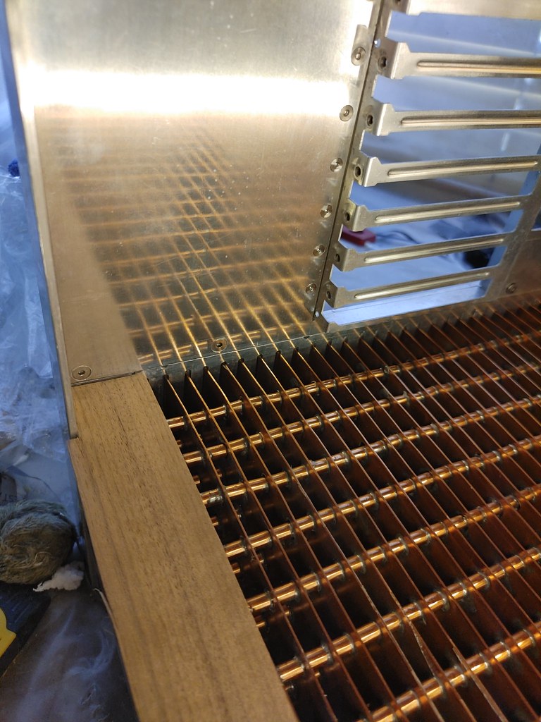
I then needed to reattach the aluminium frame to check the cast resin level - still a mm to be taken off one side. The other side with this polished top fill port is more problematic - milling needed to tidy the 1/4" plate with 'HUSH' at the top to sit flush as the original milling for the aluminium angle leg to sit in and be bolted to it is off and needs extending by ~2mm, so new aluminium legs needed for the now repositioned countersink screw holes, new aluminium angle leg with the optical drive slit, as it sits too high atm (the drilled holes to bolt to the copper wall are 3mm of so too low on the legs, so the top edge sits too high and can't be milled to sit flush with the veneered manifold...
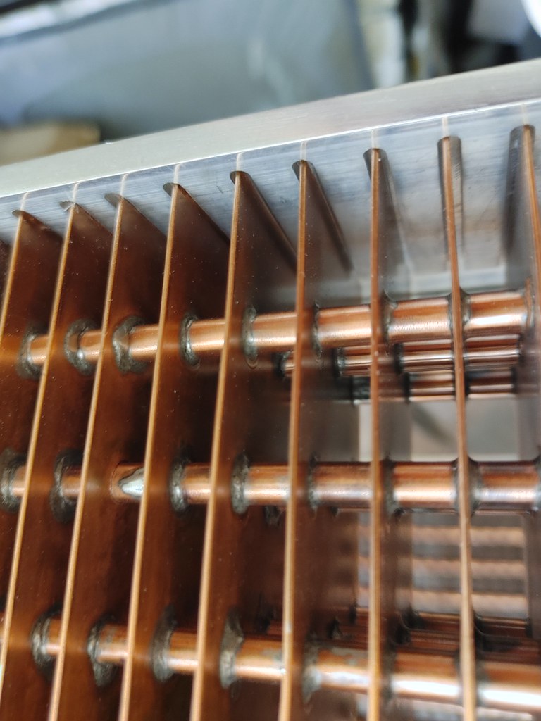
Fiddling around to get the fins at the top to sit high in the slots to try to get a flush fit at the top of the case between the aluminium frame and veneered manifold, a few mm would be milled off the top of the aluminium plate here...
 20220717_133331_HDR
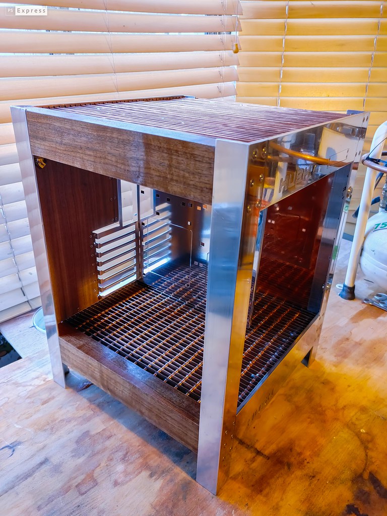
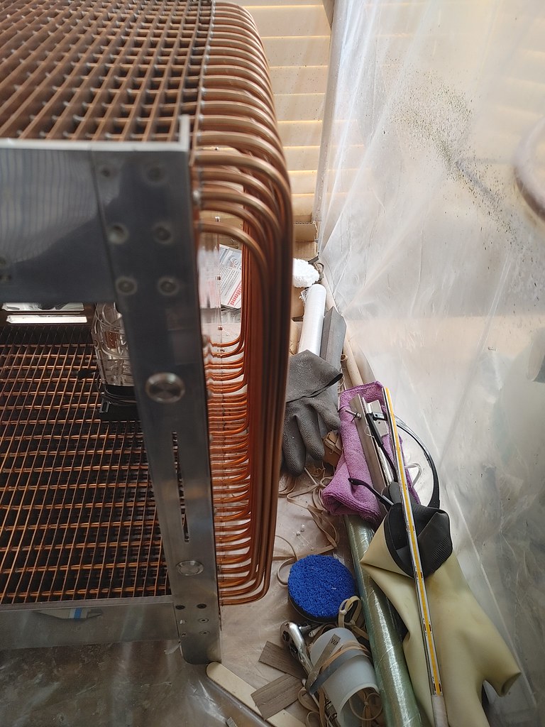
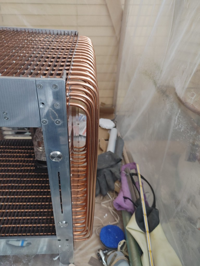
Few pics of the case with lacquered polished pipes at the side - spraying this had been difficult - the structure of 16 rows of 3 pipes curving with a flat wall behind meant in ensuring all the polished copper pipes got covered that there ending up being a lot of overspray of lacquer on the flat copper back wall and orange peel, and some overspray on the pipes at the ends.
 20220725_133608_HDR
 20220725_133600_HDR
May be able to polish this down later to reduce hopefully, but regardless the pipes catch the light beautifully, giving a copper red glow in daylight and catching salmon-white on the pipe arrays in white artificial light, that doesn't show up that well on a phone camera...
 20220725_134054_HDR
 20220725_132806_HDR
 20220726_013827_HDR
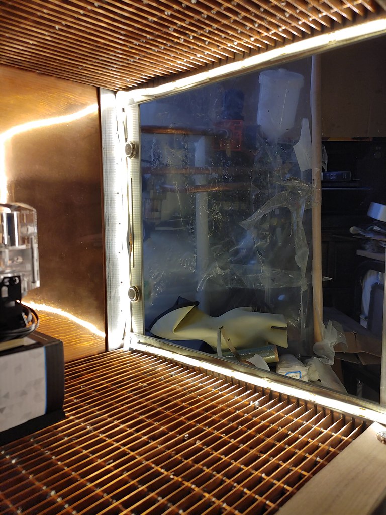
On a brighter note (pun unintended) - I jerry-rigged some lighting in just held in place with some micropore tape (the lighting strips do have 3m adhesive backing for attachment- COB LED strips (direct mounted LEDs to a PCB strip allowing more LED density compared to usual LED strips - these are around 400 LEDs/metre with a silicone diffusing coating, so much more continuous bar or light rather than specular... I tried a square strip behind the front aluminium frame - quite difficult to see the LED light strips from normal viewing angles. A full square is probably a bit too much, though will be using some very thin lower wattage 2.7mm thick LED strips rather than these, which are 8mm wide with flexible PCB strip and contact points to the sides, so should be a bit less bright. I may remove the horizontal strip at the bottom and have strips under the radiator fins at the bottom front and back to give underlighting - the light bounces off the shiny pipes, but didn't get pics yet.
 20220723_081630_HDR
 20220723_081901_HDR
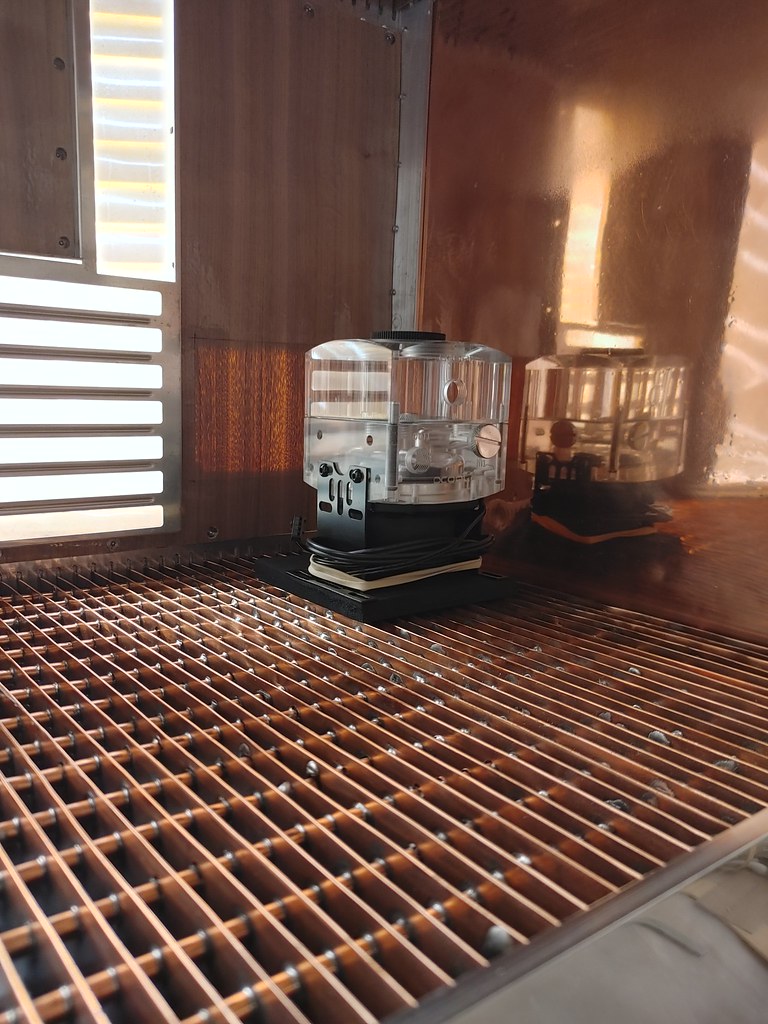
The shiny backwall gives a nice infinity radiator effect, but refpect the light strips....
 20220723_081920_HDR
 20220723_080140_HDR
The effect of underlighting under the fins looks really nice.
 20220723_081846_HDR
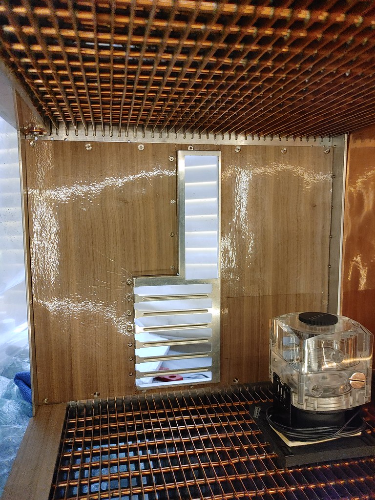
I added the veneered wall - still unattached and looking a bit hideous here as the low tack plastic sheeting is still on it, and the veneer is still unattached (as are the venner sheets for the manifold, that have gone a bit wavy in the recent heat and are unttached still so all a bit wonky..just to give a rough idea...
 20220723_172100_HDR
 20220724_170804_HDR
 20220725_132841_HDR

 20220927_233929
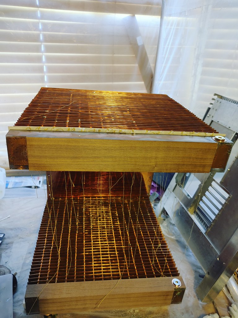 20221001_090522_HDR
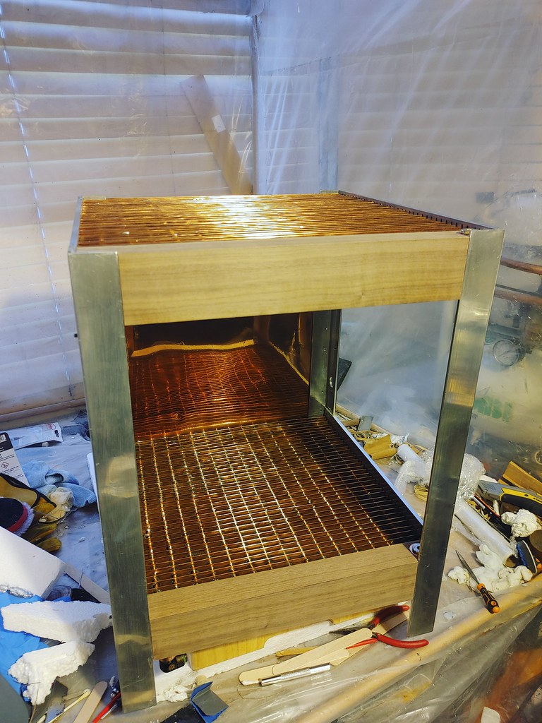 20221001_174130
 20221002_183605_HDR
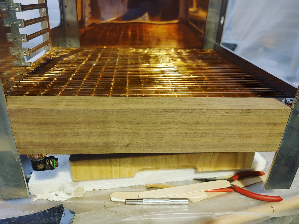 20221001_174349
 20221002_184303_HDR
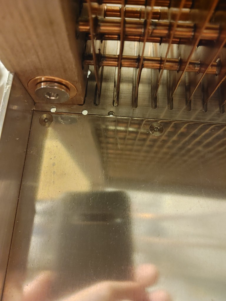 20221002_184519_HDR
 20221002_185324_HDR
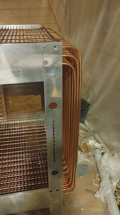 YouCut_20221002_192732601
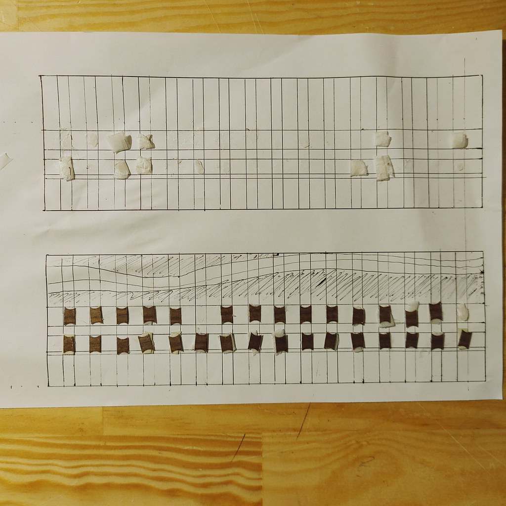 20221003_201736_HDR
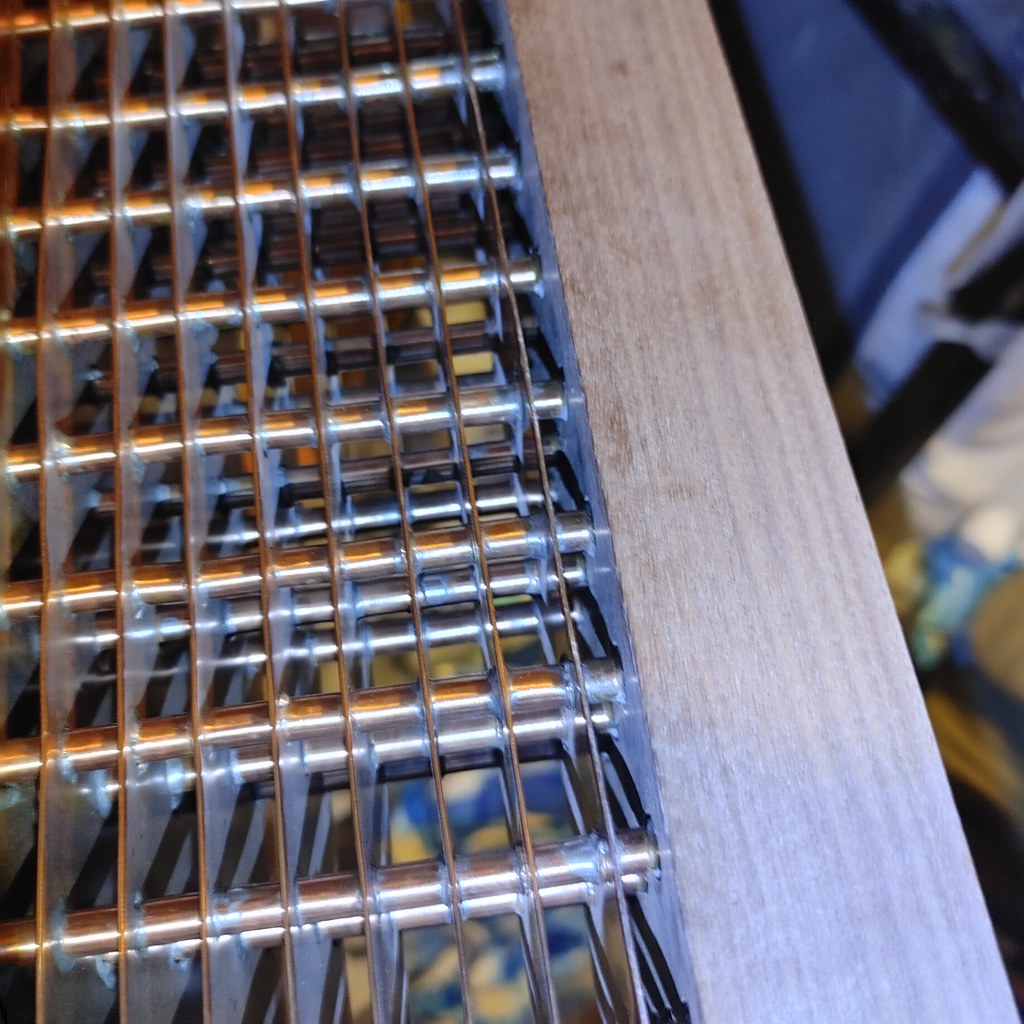 20221003_195451_HDR
 20221003_201125_HDR
 20221003_201209_HDR
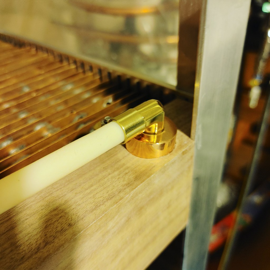 20221003_201614_HDR
 20221003_201637_HDR
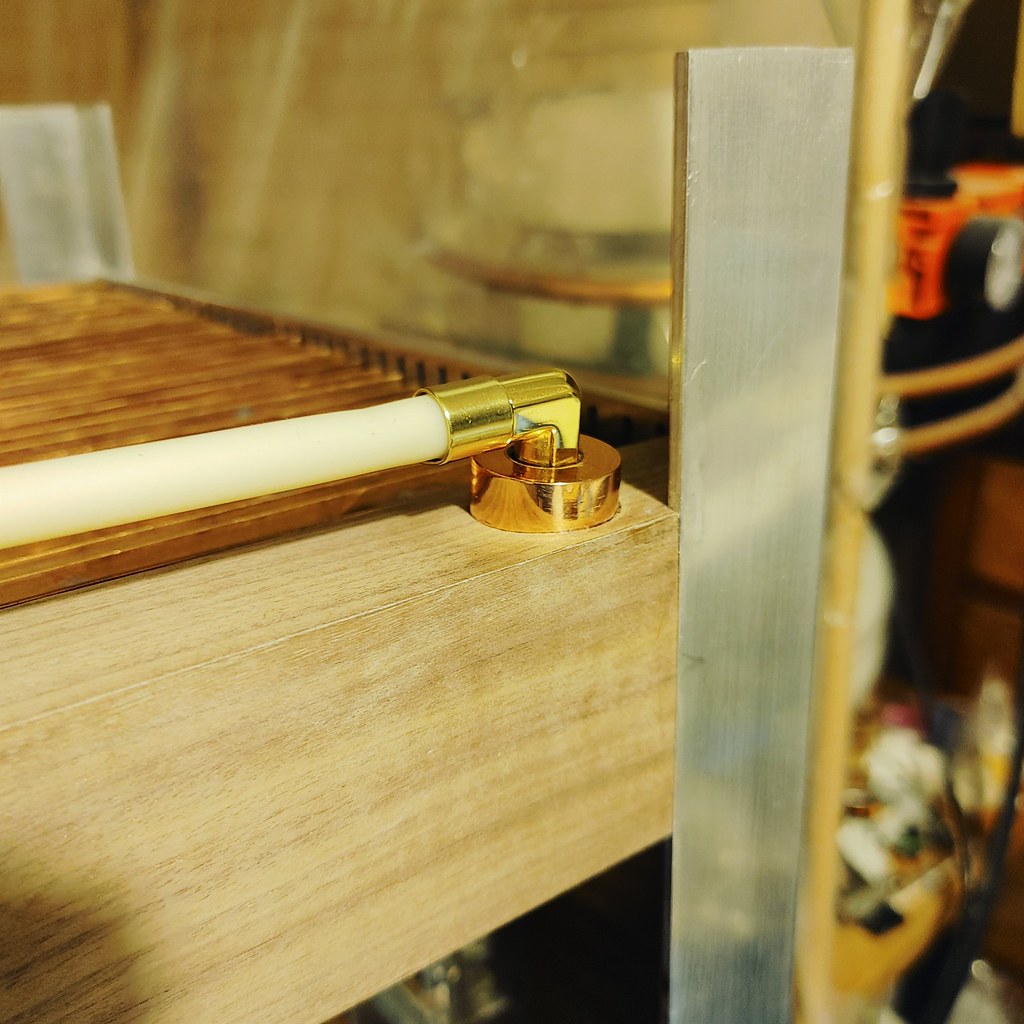 20221003_201633_HDR
 20221016_183656
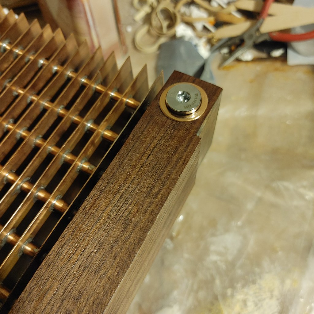 20221016_183641
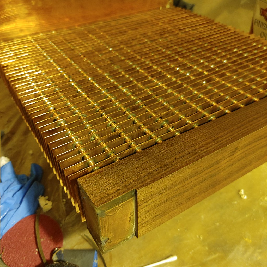 20221016_183631
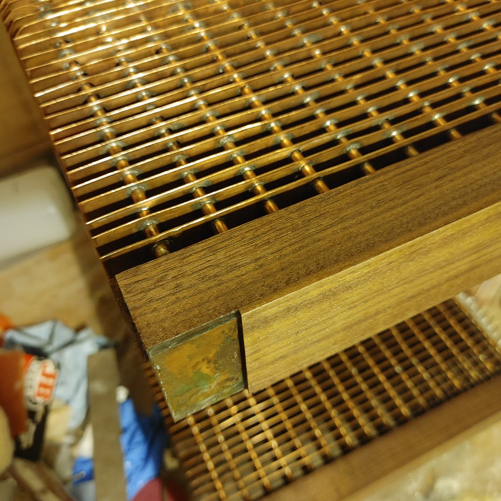 20221016_183614
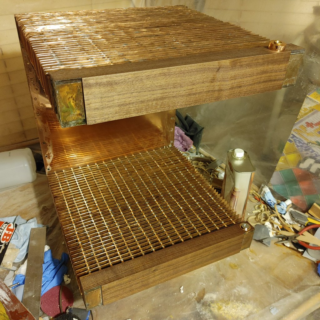 20221016_183605
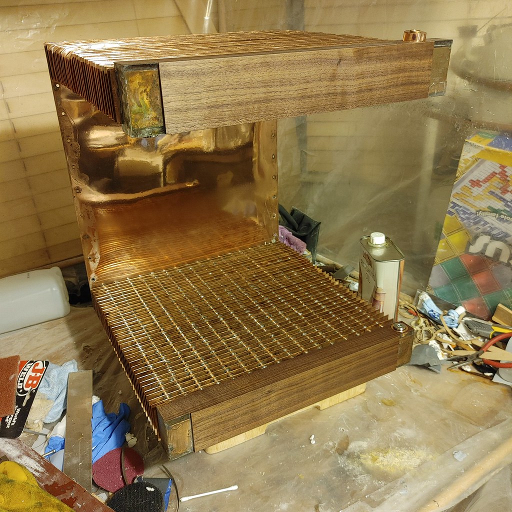 20221016_183548
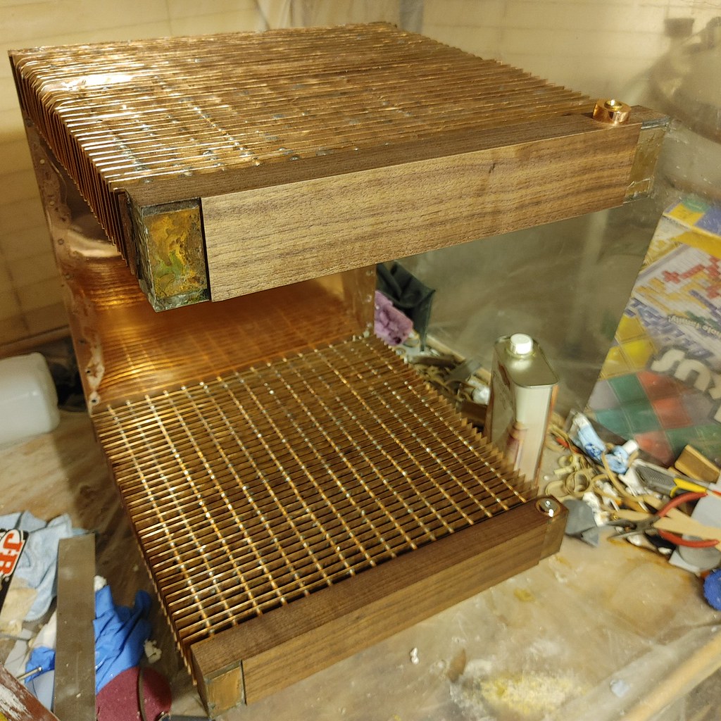 20221016_183600
 20221016_183456
 I think I may have missed that you polished up the internal back copper wall.
")

 20221018_170514
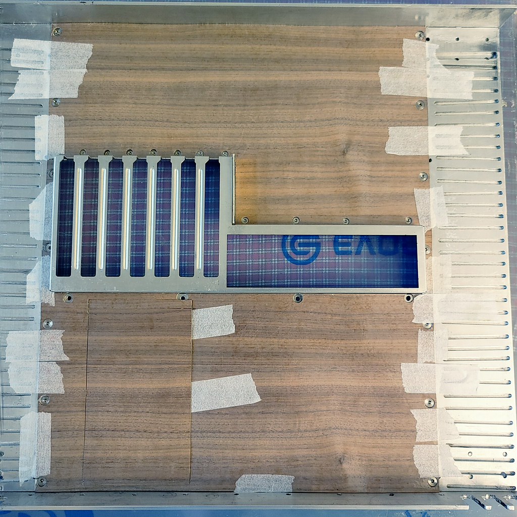 20221021_171910_HDR
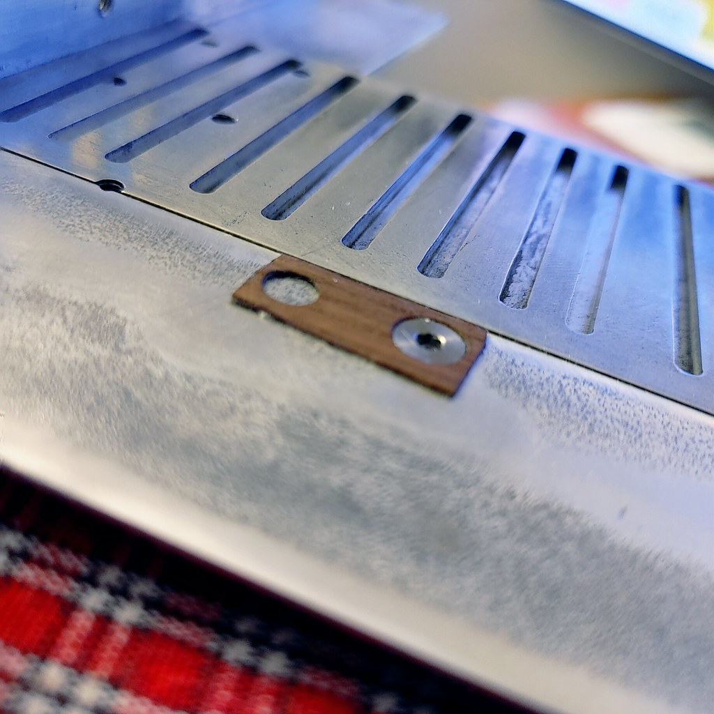 20221025_194226_HDR
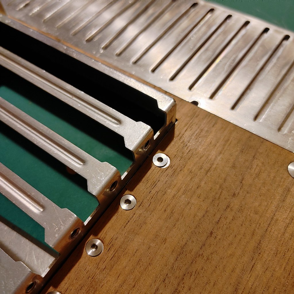 20221103_154808_HDR
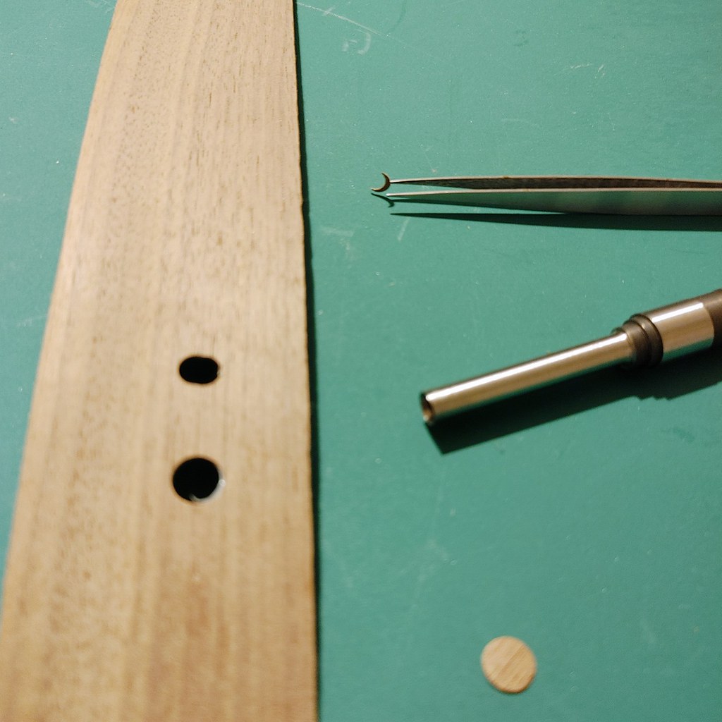 20221103_154851_HDR
 20221103_155407_HDR
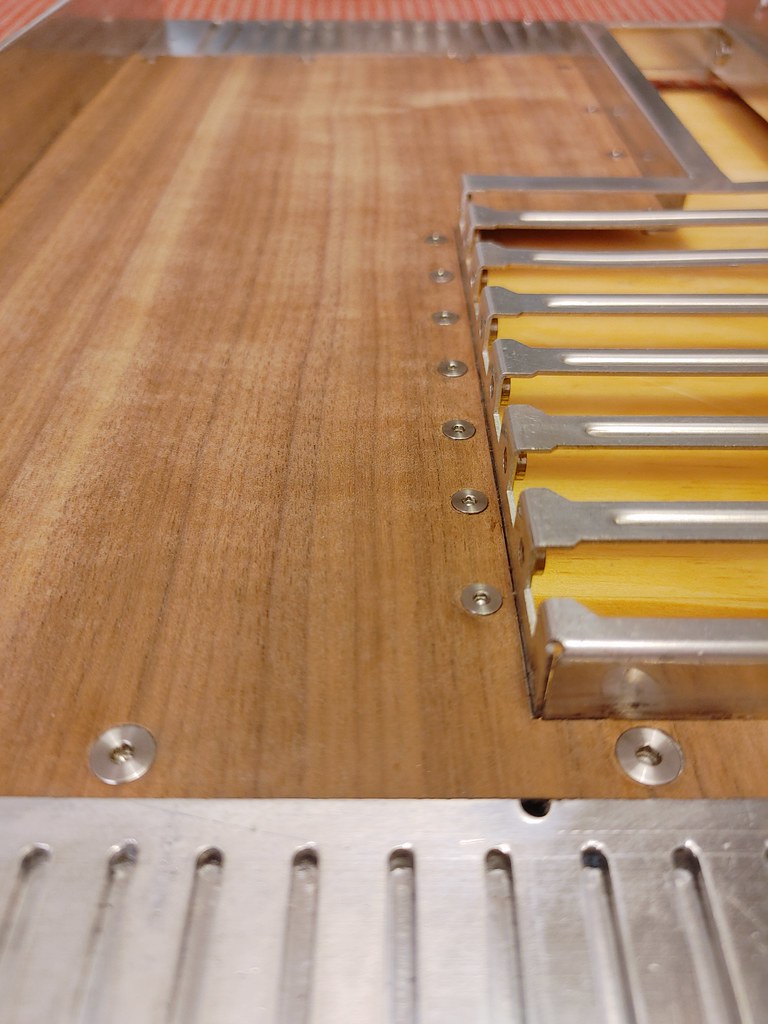 20221105_180157_HDR
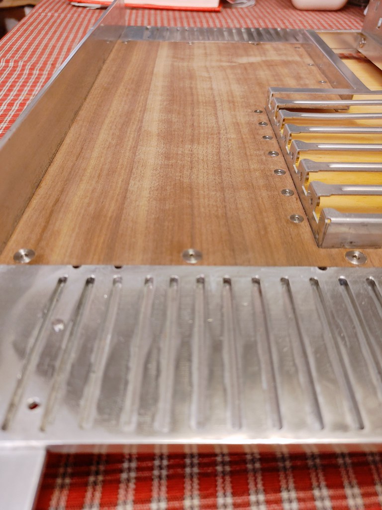 20221105_180245_HDR
 20221106_144008_HDR
 20221106_144015_HDR
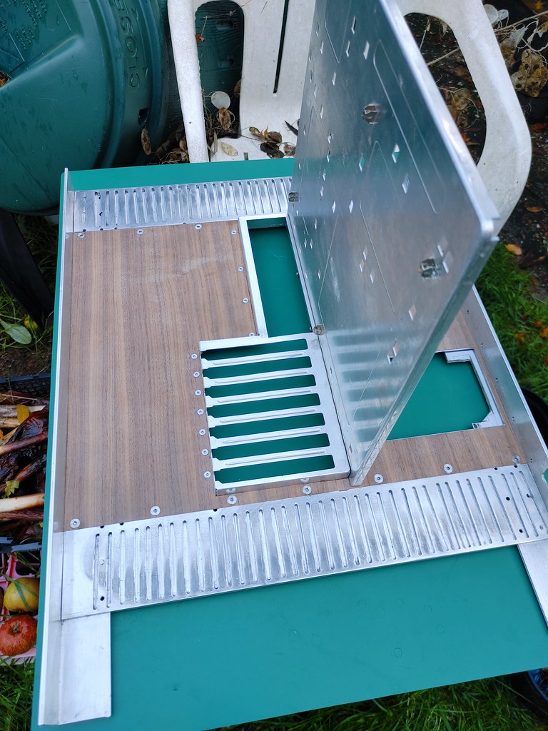 20221106_144205_HDR
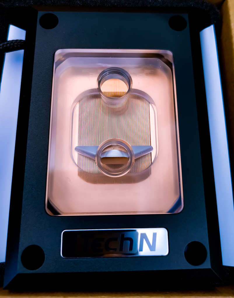 PSX_20221106_165719
 20221106_142935_HDR
 20221106_143136_HDR