Project: Somnolent High Ground (raised bed)

Soldato
Joined
4 Jun 2007
Posts
2,762
Location
Watford, UK
What's this? This is a bedroom revamp for my son - who will be 12 by the time this gets going.
Why here? This particular sub-forum rather than the Project Logs forum because there isn't (at least immediately) a PC component to it...although there will be desk, networking and so on as things progress.

So here's the plan. Floating bed made out of C24 carcassing timber stained black. Screwed to the wall on two sides with the floating corner suspended from above with a 10mm marine-stainless rod. Why? Because I have a couple of 1.5m lengths of the stuff left over from another project so it's "free" :D
Height is a compromise. It's heigh enough that an adult can sit on the sofa (provided they've stooped enough to not brain themselves on the bed frame) but low enough that he (my son) should be able to sit fully upright in bed without lobotomising himself on the ceiling.

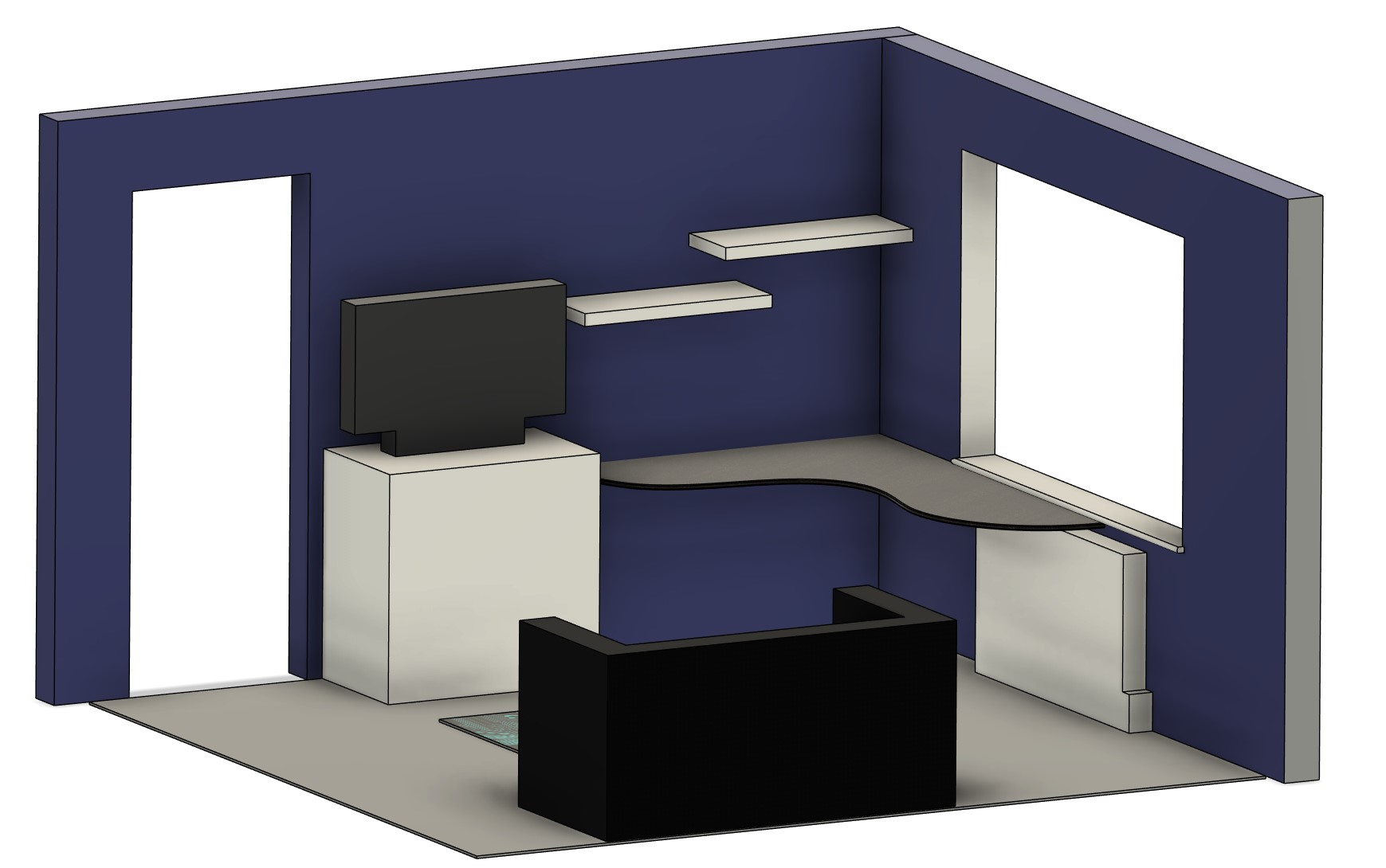
I've drawn everything out in CAD to get a feeling of how it will look as well as the heights and clearances. These are the views hiding things so you can see "in".
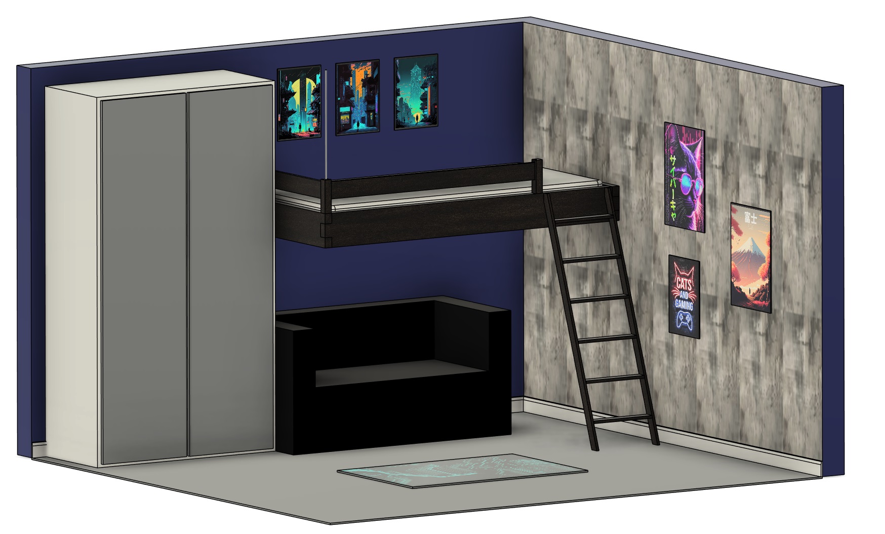
Plan1.jpg


Plan2.jpg


So, that's the plan. Progress is going to be dependent on I'm not full of cold and various other jobs: the wallpapering, moving the network sockets (obviously these are on the wrong side of the room), fixing the carpet and so on...but a lot of that is at least picture-worthy progress :D
 
Last edited:
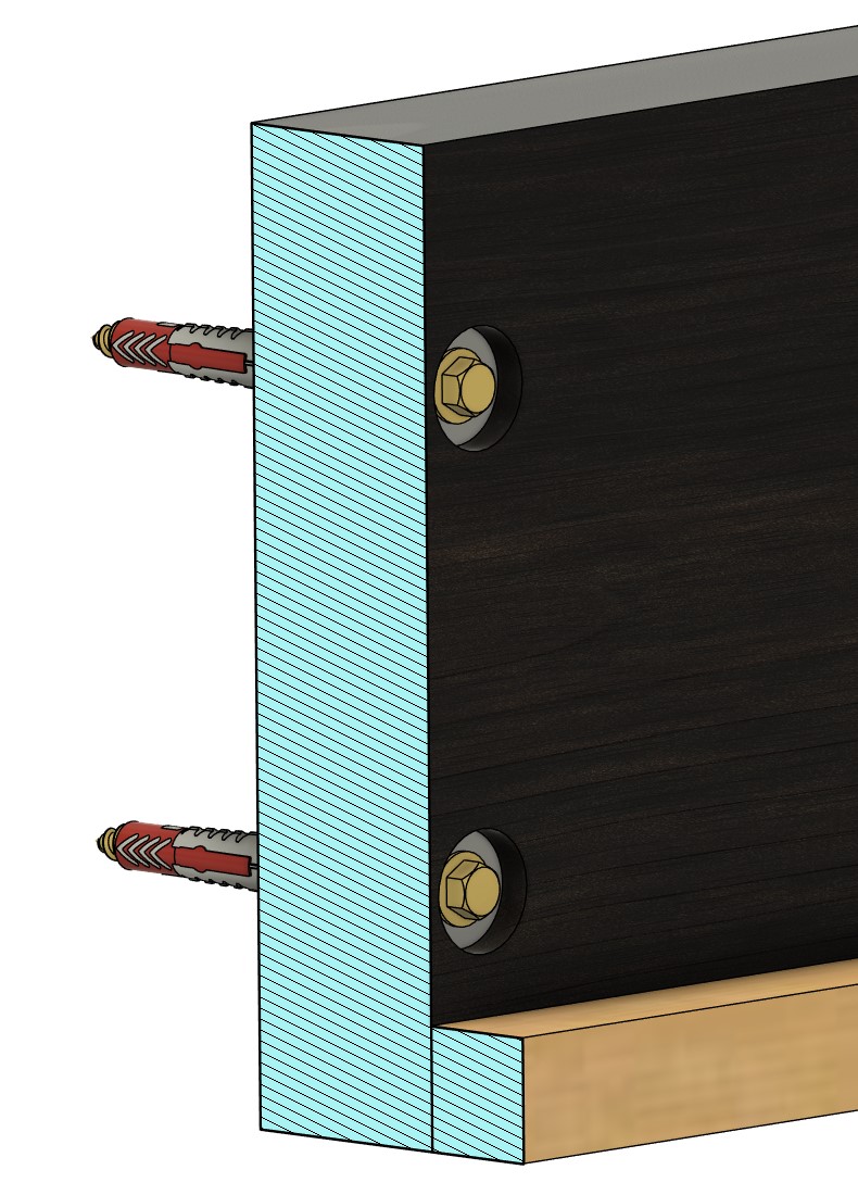
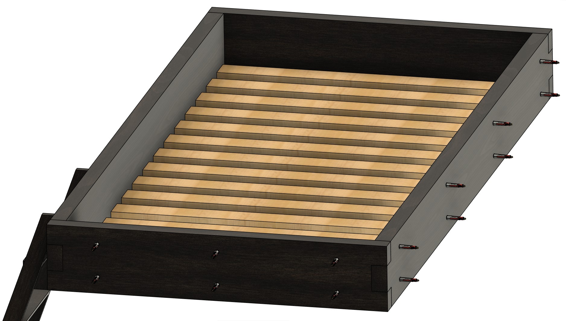
"Drawn everything up" you say? Er, yes!

WallFixings1.jpg


WallFixings2.jpg


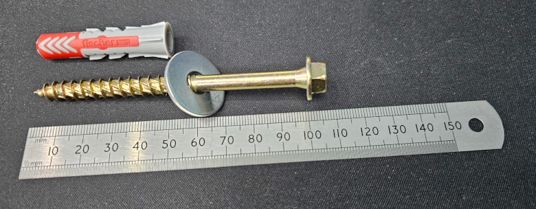
These had to be a balance or over-engineered enough for peace of mind but not so much that they might protrude into next door's bedroom! :D So these are M8x100mm coach screws and 10x50mm wall plugs. This shouldn't penetrate to the cavity that I'm assuming is present in the wall....and shouldn't go through if there isn't!
So, off to buy some I went:

 
Last edited:
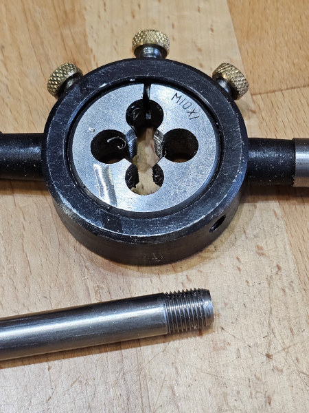
So one of the driving factors behind this project is cost (isn't it always?!). This is partly why I'm not spending £800-£900 on a high sleeper; that and I'd rather it wasn't made of compressed sawdust and involved a trip to A&E every time he sat up in bed (the height is biased considerably towards the underneath space on those). This is also why I'm using the 10mm support rod rather and defying my natural urge to massively over-spec it :D Incidentally, the most conservative numbers I've found (including safety factors etc) for 3/8" threaded rod (which is slightly smaller and a lower grade material) are that it can support 270kg. That should allow it to support more than twice the entire weight of bed, mattress and a fully-grown, overweight man (maybe I'll have to change the bed myself!)....and three quarters of the weight should be supported on the walls. Other figures I've found are anything from 1.5 tons to 15 tons. These are for the rod snapping rather than the threads stripping but whichever way you slice it, it's considerably more than it needs to be. I plan for the rod to go through both timbers and I'll make a sort of recessed L-bracket underneath for it to thread into and spread the load. I wanted to use a fine thread as it should be stronger (load spread over more threads and larger minor diameter) but I didn't want to have to buy a new die to cut them. Will the cheap extra-fine M10x1 die I have cut the mustard steel? Well, it was a joy to get started but yes!


It's difficult to work and it'll work-harden on you but it does give a nice finish if it doesn't ruin your day first. I may well buff it to a high polish before installing it....but that's definitely jumping the gun!

I've got a matching tap too so I can create matching threads in the bracket and in the loft. The plan there is going to depend on exactly where it comes through the ceiling. The one thing I do know is that it will come though in the area that's full of glasswool....because life hates me. I bought a full-face respirator last time I had to disturb that stuff because otherwise, you really start hacking up a lung as the bits of glass get in. Seriously, not something you want to deal with, nasty stuff. The rod will likely come up between joists so I'll probably need to bridge across two of them and have it thread in, in the middle.
 
So, that concept proven, I moved onto worrying about the ladder. Easy, there's a nice one tucked away at my mum's house from when I had a bed similar to this (but with solid concrete at a very self-lobotomising distance...probably explains a lot!). Went down there....nope, gone. So I started planning to build one myself and pondering how best to do it: straight-flight, tapered*. Is it worth just buying one? Google says....£600 to £1500 :eek: Yeah, that's not budget-friendly. I did find one for £150 and I was considering that...until I looked at online auction sites and stumbled upon vintage step ladders.
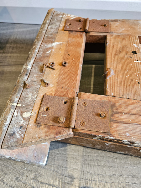
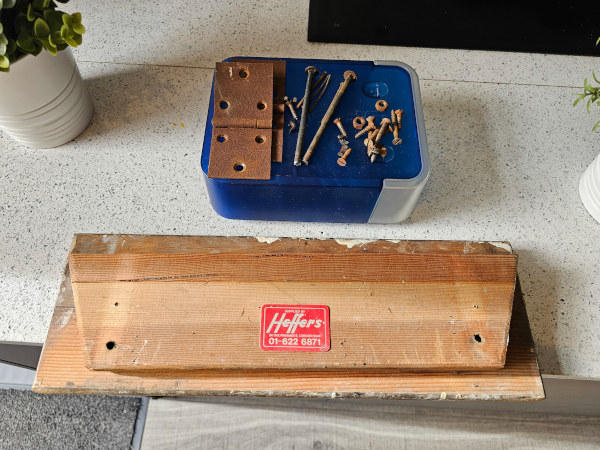
So I bought this for a tenner plus a round-trip to collect it:


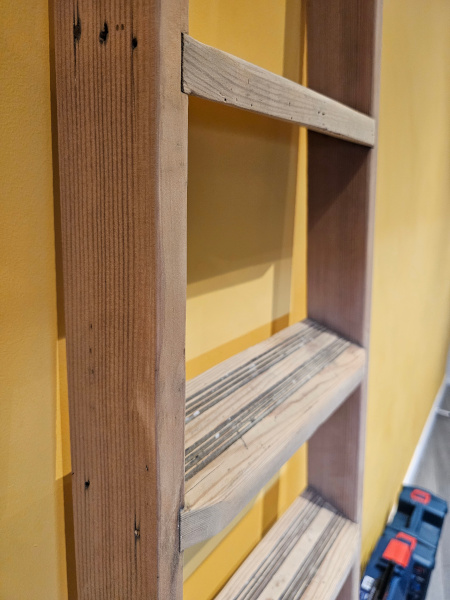
Removed all the rusty hardware and all parts I won't need:


I'm not sure of the exact age of this ladder but given that London hasn't been 01 since 1990, that puts it at least as old as 33 years.


Now I just need to sand this back and stain it black. This is, after all, a (pre-)teenage boy's room! I'm looking at Rubio Monocoat in Charcoal for this. It's pricey but it looks like it'll give good results fast and easy...and with the desk, ladder and bed frame to do, I've got a fair amount to cover.


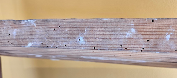
One thing I did find was this: :eek:


I'm guessing it's historic and no longer active....but I've got some wordworm killer in the post just to make sure. It's not structural and is confined to the top stop....but I'd rather be sure that both of these stay true!


*this all suggests I have far more of a clue than is really true. The truth is Google and osmosis :D
 
He could probably see the TV from bed but it's going to be an Android TV box so worst case I can kill off the WiFi to it on a schedule.

There's a good inch of space round the mattress in all sides so I'm hoping that should be enough to change the base sheet; the mattress he has isn't heavy (doesn't have to hold the weight it would for an adult) so it can be lifted easy enough. Still, might be worth mocking it up to make sure I wouldn't be better to drop the sides a bit; make it slightly less enclosed.

Studding? The screws through the sides? I rotated the picture so you could see both sets. They attach the sides to the walls which I also removed from that pic so you could see them.

I have to admit that the idea to make it raisable did come to mind and I did even look at what might be involved...but then I decided I was probably over-complicating it enough already! :D

Rope ladder: I suggested bolt-on climbing holds on the wall....but it turns out I have boring an unappreciative family ;) Also suggested wall boxes (like cube shelves) that served as a sort of staircase...but that was shot down too. I plan to make some metal hooks so the ladder can be hooked onto the edge and possibly also onto a wall bar to stow it out the way. Can't find anything ready-made and it shouldn't be too hard to bend some flat bar. Famous last words, of course!

@LePhuronn I'd wait until you see how successful it is first! ;)
 
And so it begins!

First up, a revision of the plan. Had a think on what JPaul said about changing the sheets and I don't think he's wrong. So I've re-measured the thickness of the mattress - the original plan was to replace with a small double but we're now keeping the existing single - which has given me back an inch of height. I then dropped the height of the side timbers from 8" to 6" so it should expose it another inch. What's with all these inches here? Simply because all the timbers are nominally in inch sizing so these will now be 2x6 instead of 2x8's. I've also revised the ladder in the picture so that the taper, angle and pitch are correct - can't have it inaccurate now, can we!? :D
Also, one of the pictures has been swapped out.

Plan3.jpg


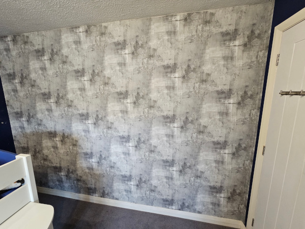
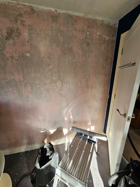
So first up, stripped the wall, filled the holes (previous pictures) and sanded it.


Whilst we waited for the filler to dry, we started the ladder. Still needs the grooves in the treads doing but definitely an improvement!


Wallpaper should be going up tomorrow :D
 
Yesterday, I got wood! (Nope, not as sorry about the depths I just sank to as I probably should be :D )


Everything has been roughly cut so that it would fit in the car. Both timber yards produced a hand saw to cut off the purchased amount....by I played the lazy (but prepared!) card and whipped out a cordless bandsaw. No way I'm cutting 15 slats by hand while standing out in the cold!
The green stuff on the right is pressure-treated. This means it shouldn't rot when left outside. The downside to this is it means at some point they felt free to leave it outside and both are damp; one is really quite wet. Hopefully it should dry some left in the kitchen until the weekend. I daren't measure or cut it until then as it could change. I fear it may also cup more than it has already so I may yet be hassling my neighbour to see if it will fit through his planer thicknesser - if it's going to be clamped against the wall, I want maximum contact area, not just a strip.
Closer white bits are the slats. Currently at 1m each, they will need to be cut down to about 920mm but I'm waiting until I actually need to fit them since if it ends up being 930mm, I'll have problems!
Further white bits are the guard rail but with a split splat on top - didn't spot that when I cut or loaded it in the car...somehow.
The red/brown bits are the battens for the slats to sit on and the posts that support the guard rail. The joy of timber is that 25x25mm battens measure.....that's right, 19x19½mm. Should be ok, just irritating. Even the "47x150" is 45x146mm. I've adjusted it all on the plan. Daft though it may sound, it makes a difference to the measurements that stacks up - the ladder now needs to be 10mm longer than it was when all the timbers were nominal. This is why I've not cut it down just yet!


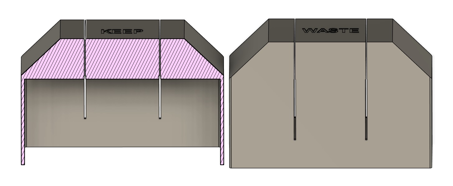
Designed saw guides to be 3D printed:

SawGuides1.jpg


Thing is, I KNOW that I'm no joiner so I'll take all the cheating I can get! These should - at least in theory - make sure that the cuts in both pieces are the right width and to the right depth (saw will have a spine to hit the top at depth) so the joint fits together nicely. The difference between the two is that the slot is moved over by the kerf of the saw. Over-thinking it much? Yeah, probably...but that's how I do it :D
 
Well, sometimes you gotta raise the stakes to encourage the learning! ;) Extra mattress in the 'landing zone'?!
The guard rail is 6" above the top of the mattress so it ought to be fairly idiot-proof....although when I was a kid, I managed to turn 180° half asleep, lay back down, backward roll off the only open part and bounce down the ladder....so it goes to show, you can always find a more talented idiot! :D
 
Got the wall-mounted timbers cut and drilled today. Had a practice at cutting the joint and found that the wood was so wet that the saw I bought to go with my guides wouldn't really cut. A chisel was hard going too. Although I did manage it (with a jigsaw and rasp mainly), the joint was somewhat untidy because the wood had cupped.
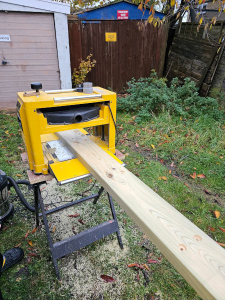
At that point my neighbour showed up over the fence so I commandeered his planer thicknesser :D We fed the timbers through with the concave side downward until it was flat and then flipped it to do the top. This should make the joint easier to do...but we also decided that the three other corners could be much simpler butt joints with no appreciable effect on the strength. The floating corner is the one that needs to be jointed so that the rod can go through both timbers. So I've recut them to the correct new lengths and tomorrow we will begin drilling holes in the wall.
We also had a think about securing the guard rail posts so they don't pull off. One can be screwed to the wall - sorted.
The corner one is mostly held by the rod going through it but could rotate. A dowel (steel, obviously :) ) should stop that.
The post by the ladder we looked at half-lap joints but it's awkward to get them in line etc. Finally decided that a pair of (much) longer 10mm steel dowels would but support it and also stop it spinning.
I've got pics of some bits but I'll try to get them up another day.
 
Ok, pictures of the first day as promised and second day following that.

My neighbour's planer thicknesser after it's chewed through the timber. We think the wood was thick enough that it stayed cupped as it went through the rollers and hence was actually flattened. Thinner wood can be forced flat by the rollers, cut and then spring back to being just as bent as it was before.


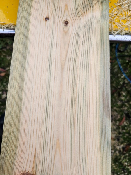
A close up (you can click for a larger version as you can with most of the pics in this project) of the timber after it's been cut. The green is the anti-rot treatment. We've skimmed off enough of the flat face that it's starting to go clear but the sides would be like that all the way through. You might be able to see how wet the timber is too. In some patches once we'd skimmed off the outer surface that had dried, it actually felt wet to the touch. Definitely a complication I could have done without!


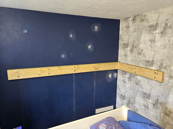
So, after flattening them off, I cut the wall timbers to length, drilled all the holes and screwed them to the wall


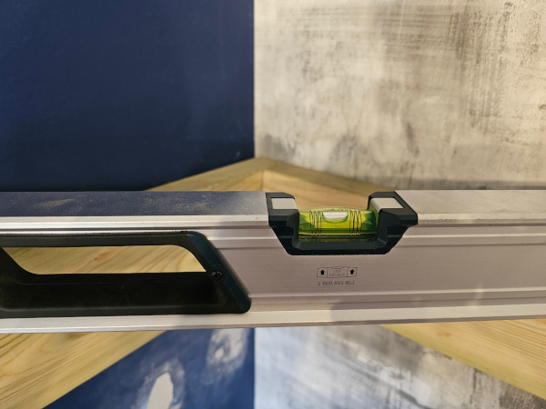
Close enough, I'll take it! Some of the error is undoubtedly that the edge is also not flat/straight. He's certainly not going to roll out of bed anyway!

 
Having tried cutting a test joint on the off-cuts of the first two timbers and finding it hard work, I modified the plan so that only this one corner was the only proper carpentry joint. The rest will be butt joints for ease, simplicity and time.
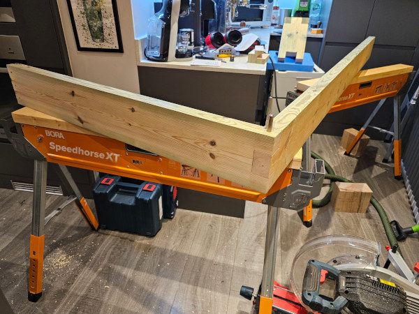
I left the floating timbers long and cut the joint into the end. That way, I could lop off the joint and try again if it went horribly wrong. For a second joint ever (after the test one) I think this is quite respectable. Sure, it's no professional joinery but given the wet wood, it's pretty good :D


The 10mm drill bit goes all the way through. This is where the support rod will go through the whole joint. The 6mm drill bit goes through all three pieces but doesn't come out the other side. This will be a 6mm stainless rod....because I have some lying about :D It will serve to pin the joint together but mainly to stop the guard rail post from spinning about the support rod.

I had to work in the kitchen because it kept raining. Luckily this is a project that my wife approves of, so I got away with it :D Not the most helpful layout of space to try assembling the pieces though....as you might be able to tell! Did also mean that when I'd finished for the day, I had the bedroom to clear up, the landing ('resting' place for the tools), the kitchen and the shed (which is a workshop but really thin...and full of stuff :D)

I got the finish that we'll be using for the wood too. The Charcoal (darkest leaf at 9 O'Clock) is the one we've gone for. How it eventually looks will be dependent on the wood it goes on. I'm hoping the green won't affect it too much or that if it does, the difference between dark and darker won't be too noticeable. Main reason for using this stuff is laziness; you mix (some of) the two parts, slap it on, wait 5 mins and wipe off what hasn't been absorbed. Done: stained and protected in one hit.

 
This is definitely a textured ceiling but it's not spiky at least. He should miss it with the 800mm of headroom I've given him. Once he grows tall enough for it to be a problem, he should be teenage'y and slouch enough that it'll give him extra clearance! :cry:

Steel plate (technically it's steel sheet as it's 0.25mm too thin to be called plate :rolleyes: ) arrived today. Will get that cut, drilled and tapped to make the L plate to go underneath the floating corner.
RGBCCT LED strip kit also arrived. That's Red, Green, Blue, Warm White and Cold White...for all the possibilities of mood lighting to functional lighting. Once you've gone RGBW for the better white, what's one extra channel?! 24V PSU works, LED strip works....controller does not. I've got another controller on order - I break even on the extra cost of the kit just with the PSU so it's not a massive issue. Bit worrying that the strip was faulty at first though.
 
I haven't yet, no. This isn't a traditional stain though. I looked at those and soon learned that to get any sort of decent even coverage you'd need to sand, apply wood conditioner, wait long enough but not too long, apply stain, pray and then apply some sort of protective finish over the top. This stuff is more like an oil in that it soaks in a little bit but a bit like an epoxy in that it hardens in the surface of the wood. The desk will be done in the same stuff as well as the ladder. The desk is something like an ash veneer and the ladder is 30+ year old answers-on-a-postcard. I'll be honest, it's going to be somewhat suck it and see. If it turns out different tones on different woods (which I'd rather expect) then it shouldn't be too much of a problem. I'm more worried about how it'll interact with the green pressure-treatment to be honest. I'm hoping that it'll be dark enough that it'll hide the worst sins. Only one way to find out really :D
 
Another weekend at work :D

Steel plate turned up.


Marked it out, cut it and drilled the hole for the steel rod


Tapped the hole M10x1


Jam nut to tighten against the steel after the rod is threaded into the steel. Should stop it loosening or coming undone :eek:


Recess cut in the wood to take the steel. Don't want it on the surface where it could cause injury.


And installed. Jam nut is only placed there to show where it'll go.


We also started the ladder but I've not got finished pictures of it yet....partly because I've not finished it yet :D It already looks a lot better than it does in this in-progress picture though.


I had to wipe off the excess from the grooves with paper towel. I was using a gloved finger....but guess where the glove broke.
And that was Saturday.
 
Sunday.

Now the floating corner is all screwed together, it was time to get it hung. A nice stack of toolboxes and shims and we're level. Three screws at each corner and it would probably take its own weight...but lets not push our luck just yet :D


I put a laser plumb dot (the function of a cross laser that you didn't have a use for until now) from the floor, through the hole and onto the ceiling. Drilled the hole into the loft and stuck a rod through. Found it came out in the section full of lovely glass wool...because or course it did. It's close to a joist but still 90mm away. The plan is to get some more timber - I want structural graded stuff that's long enough to spread the load across three joists and thick enough that weight capacity isn't even a consideration....and this time, I want DRY!

So with everywhere that sells timber (at a reasonable price) closed for the day, I carried on with the battens and the slats.


There's 16 screws in each hardwood batten and 2 in each softwood slat. That should do it, right?! :D I did have fun with one screw in one end of a batten. Took me a little while to twig what was going on...but in the end, it turns out that screws just don't go into 6mm steel plate! :rolleyes::D
 
Got the steelwork done for the top of the rod yesterday. I reckon this should be overkill enough! :D


To be fair, most of that is just about spreading the load across a wider area rather than needing that much steel for strength. The smaller one is another jam nut.

I've got the hole drilled through the ceiling and a couple of 4x2's to go up in the loft. One will be for cross braces between the joists (as they're only 4"x1½") and the other will spread the weight across 5 joists. Probably over-thinking it....but better than the alternative!

LoftPlan.jpg


Right now, I've got the steel rod through the bed, threaded into the steel plate at the bottom (there was some swearing when it didn't quite line up!) and through the ceiling. Hoping to get it at least to the point I can hang it today....or maybe tomorrow :D
 
Got the steel rod all measured and marked up. Cut it to length and cut threads on it with a die. All went quite well... until I took the die back off and it chewed a number of the threads up as it went. Anything I did just made it worse and I just don't trust damaged, deformed and flakey threads for a safety critical use. I may be cavalier but I'm not (usually!) stupid. I checked for morbid interest and that's £25 worth of steel I just wrote off. Well, I can cut the ends off and use it again but not for this use. Fortunately I have a couple of backup pieces left over from the same previous project.

I think that the steel may have work-hardened or galled. That or the die isn't great. I could buy another die and have the same problem again so I've sworn for a bit and then set up the lathe to single point the thread. It's a faff as it involves changing all the gears (literally replacing the cogs on my lathe) and that means tidying up enough that I can open the door. All of which is why I (and many others) usually use a die instead but I've done a test thread on the offcut and it's a lot better.

All in, I think I'd probably have been further along if I'd just stayed in bed today...not that it was an option!
 
Yup...amongst the other things going on, of course.

This is the dodgy thread I wasn't happy to use:


This is the single-point cut version at the top of the rod. The same has been done for the shorter thread at the bottom. I've yet to mill a hex on the smaller round part so that I can put a socket on it and screw it into the plate in the bed in the room below.


Better, don't you think?!

Some more quick pics of things I've been doing in between.
The posts for the guard rails:


I did one of these because the support rod has to pass all the way through it so it needs to be slotted onto the rod before it's installed...and while doing one of them, I may as well do the other two.

This will disguise the hole in the ceiling that has grown a little larger (25mm diameter) than I'd originally intended. The rod was 0.4° from the vertical and that doesn't sound a lot but over a metre it equates to a few mm at least. This might be lessened with the single-pointed thread which should be perfectly concentric....we shall see! The other possibility is that the recess cut into the wood for the steep plate, wasn't perfectly flat relative to gravity, only to the edge face of the wood which was still in as-supplied condition. This seems far more likely to be honest. Either way, this should hide my failings and I can probably get a bit of soft wrap in the hole to stop a draft coming through. One thing I found is that the rod cannot be allowed to touch the plasterboard. If it does, when you walk across the room, it rubs against it and sounds for all the world like someone's walking across the floor above you. It might stop when the column of boxes is removed as that ought to isolate it from the floor...but not touching the plasterboard is preferable anyway.

 
Ok, some decent progress now. First, the ceiling grommet installed. I've got the rod installed too but there are better pics of that.


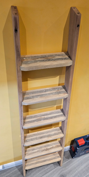
Next, the stained ladder that I only got a half-finished terrible picture of. This, a 95% finished terrible picture for you :D


Still needs cutting down to length but I've been waiting for the real-world final height of the bed rather than doing it off-plan. Also needs some hooks made but I've not got round to that yet.

So I spent the morning making up angle braces. The support in the loft is a 2x4 standing on edge; because it's strongest in the direction it needs to hold the weight that way. Thing is it could then tip over...well, it couldn't because there's a steel rod passing through the middle of it but you don't want it wobbling and trying to fall over :D
So these should brace it against that. Counterbored for the screws so I didn't have to use foot-long screws....a bit much even for me!
The straight bits at the bottom are cross-braces to go between the joists. Partly to add strength and partly to supply a more stable surface for the beam to sit on. The joists are positioned at somewhat random spacing and are a bit twisted so it's not a flat surface. I know they're strong enough to support the load because the middle of the loft is boarded and that's taking my weight plus the usual hoarding of 'stuff' that accumulates in a loft. I left the beam at full length to spread the weight across as many joists as possible. It's not like it's going to be in the way under there.


Cross-braces, beam and angle braces installed with the rod passing through all of them.


The steel plate is cut from the same piece I made the angle plate for the bottom of the bed so it's 6mm thick. It's largely something for the flange nut to bear against (so it doesn't just dig in) and to spread the weight over a larger area....which is also why the flange nut is so over-sized. Jam nut on the top just stops it from loosening.


The joy of working in the loft is that the insulation up there - courtesy of a 90's or 00's 'Insulate your home for free' job the previous owners took up - is glass wool. Originally it had been just thrown over the top of the boarded area as well. I disposed of that because it meant you couldn't use it for storage. This stuff if you disturb it, gives off particles of glass tiny enough to float on the air...and be breathed in. I've done it once (unknowingly) and you end up almost literally coughing up a lung. That's why I've invested in looking like Artyom for the entire time I will disturb it. It's possible some or even all of this stuff predates the glass wool and isn't as evil....but I'm not taking the risk, hot and drippy though it is.


So with the rod in place and half a guard rail up, it seemed like a good time load-test it. Tested and approved!


We also got my weight as close to the floating corner as possible and then my son's as well. Not even a suggestion of a creak. Happy with that.
Last guard rail post to do today and the ladder. Rather than chisel the bottom of the slot in the posts square to match the guard rails, I routed the bottom of the guard rail round to match the slot. The top edges have just had a much smaller round-over to remove the sharp edge. I'm undecided as to what to do with the top of the slots. I could leave them as-is or I could do a 3D printed cap for the top - which I fear might look naff - or just some wooden inserts to fill the top of the slot. I think I'm leaning towards that last option...especially as it wouldn't require removing the support rod to thread something over it! *facepalm*
 
Back
Top Bottom