Scratch Build: Blu & Red Aluminium - Sponsored by Gelid

Associate
Joined
7 Jan 2009
Posts
163
Thought I'd use my newly found free time to get back to a hobby of mine. Building PCs. Although this time I'll be realising a dream of building a case from scratch.

Edit:
Most recent picture:
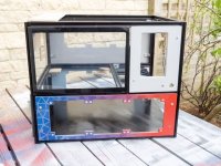
QvaQxqOl.jpg

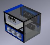
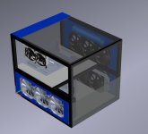
Here's the latest CAD
cs0sWfBl.png.jpg


Sponsored by:
nN8Yq3Al.jpg

The issue I had was not being able to find a case that could fit both the 420mm and 360mm rads I have. Well, there are cases out there that will do it, but just not perfect, and fairly pricey. So I figured if I'm going to spend a load of money on a case I may as well build it myself.

The plan is:
- 420mm rad with push/pull for the CPU
- 360mm rad with push/pull for the GPU
- 3 X 120mm fans for exhaust top back.

=============================================
Edit: Specs:
Current specs are as follows:
7800X - hopefully with an overclock once this gets done.
Gigabyte X299 AORUS Ultra Gaming Pro
32gb Corsair Vengeance LPX 2666Mhz
AMD Vega56
Samsung 960 250GB NVME
Samsung SM951 250GB NVME
Antec AX1200
Asus Xonar DX Sound Card (maybe, I've got it in a box somewhere so may as well use it).

The watercooling plan is as follows...
CPU Loop:
Block: EK Supreme HF
Rad: 420mm EK Coolstream XTC 55mm
Fans: 6 x Gelid Silent 14
Pump: EK DCP 2.2
Res: 150mm Tube (This may change depending on where they end up being mounted)

GPU Loop:
Block: EK Supreme HF with custom mounting bracket.
Rad: 360mm Generic approx 25mm thick. I've had it for years and it's a trooper.
Fans: 6 x Gelid Silent 12
Pump: D4 with custom speed controller (because it's so damn loud!)
Res: 150mm Tube (This may change depending on where they end up being mounted)
=============================================

Might go RGB on the exhaust fans. Undecided on that one.

I've put together some other provisional CAD for the layout. Will make adjustments as I go. Just trying to get a feel for the space usage of the larger components.
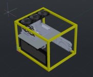
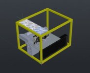
dELMPA3m.png.jpg

Js5gMx2m.png.jpg

Overall dimensions will be around 500mm x 400mm x 400mm. I've already ordered the wrong lengths of extrusion as I was originally planning 600 x 400 x 500 but it just seemed a little too large.

The plan is to use 2020 ali extrusion for the majority of the frame. Having a lower and upper section. Lower section will house the PSU, rads, HDDs and pump. The upper section will house the mobo and GPU. Might do something interesting with reservoirs in the empty space.

Also considering RGB options as the plan is to have the upper section visible from at least two sides with either tempered glass or acrylic. The lower section will have some obstruction, either total blackout or a mesh with back lighting.

The pace of this build will be dictated by delivery timescales! Watch this space.

Hardware specs are from my current PC so nothing crazy. This is more about the case than the performance.
 
Last edited:
Associate
OP
Joined
7 Jan 2009
Posts
163
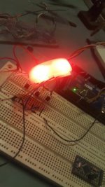
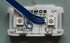
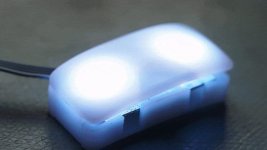
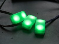
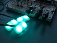
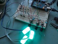
While I wait for deliveries I decided to work on some RGB experiments.
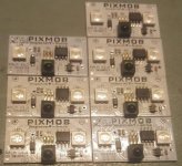
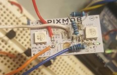
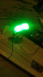
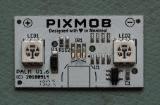
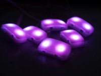
I managed to ... acquire ... some RGB wrist bands a very popular girl band concert I attended last summer in the hopes they would be able to re-purposed for something. This is that time! So I did a little reverse engineering and managed to drive them from an arduino using some pre-written RGB libraries.

Quite conveniently they come with diffusers, which is a big plus.

The soldering is abysmal but I'd been taking parts on and off for a while and couldn't be bothered to clean up considering I'm going to be reworking it anyway for the final cabling.

9CPD2APm.jpg

yB41AUAm.jpg

PjEMkETm.jpg

5J2k2fBm.jpg

There are eight units in total so I think they could be quite useful for lighting the lower section if I decide to. Could put all the circuitry on a nice little controller PCB and write some code for the arduino to interface over USB and have it all software controlled.
 
Associate
OP
Joined
7 Jan 2009
Posts
163
Got some more work done on the RGB side of things today.

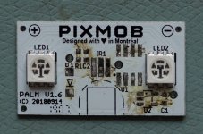
Snipped some of the larger components off the PIXMOB boards.
55rCaTgl.jpg

Removed all the smaller components.
WqHFxl2l.jpg

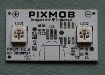
All cleaned up
0bFGXbnl.jpg

Wired in the supply voltage, red, green and blue traces.
U2JaSuzl.jpg

It works!
IGh9jC0l.gif.jpg

Did this a couple more times.
j6WavVRl.jpg

Then decided it would be nice to have some manual control of the colours on the front panel. So wired in some potentiometers.
kBUF8EGl.jpg

Here's the proof of concept wiring on breadboard.
LlKfLRZl.jpg

It's all coming together fairly nicely. Just need to buy some more ribbon cable to get the other five boards wired up and there will be 8 in total.

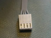
Next step will be to fit all those parts on a PCB (protoboard first probably) with headers for the RGB units and pots. Headers will be those 4-pin fan connectors you see everywhere. It should be able to run easily off the PSUs 5V rail, pulling a max of about 1A with all LEDs at full brighness.
 
Associate
OP
Joined
7 Jan 2009
Posts
163
Another update.

Got the connectors and headers in for the RGB controller today. Love that RS are still delivering very swiftly. Unfortunately still waiting on the Ali extrusion to arrive :(.

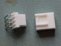
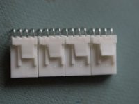
When the headers arrived I immediately realised I'd ordered the wrong ones. They are not matching sets. What a fool I am, but nothing a pair of snips can't fix.
SWgSsJnm.jpg

Slightly modified, just don't look too close.
Vj2QMHkm.jpg

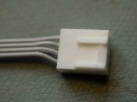
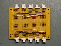
From there I crimped up the wires for the RGB units and started planning the layout of the board.
wpBbUTBm.jpg

U7C9MEym.jpg

Mocked it up a bit to get a feel for the space being used.
BWwBLrKm.jpg

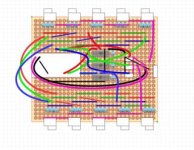
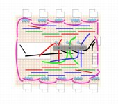
Found a really handy program for planning out the wiring of the perf board called DIY Layout Creator. Would definitely recommend as I was up and running in about 5 minutes. Very intuitive and easy to use.

Went through a couple of iterations. This is number 1:
TZK4Mzam.png.jpg

Wasn't 100% happy with it so tried again. This looked a little neater. It's missing a couple of the wires for the manual RGB pots but I will remember them when it comes to it. I hope!
uG25w5Cl.png.jpg

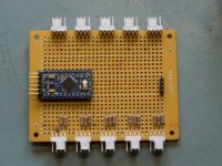
This is where I ended it this evening. headers soldered on, resistors in place. I decided to leave two sets of current limiting resistors empty as I've only got 8 of these RGB units and I may want to add some RGB strips in later on. Not knowing the current usage of them at the moment I'll leave it to later to decide what's required for them. Allows for some flexibility down the road. Also started cutting a placing the jumper wires.

The worst part of this. To make it easier to wire I decided to use red, blue and green for the different colour channels but I could not for the life of me find any green wire in my draws, so white it is. I can only appologise.

yGcyXFXl.jpg
 
Associate
OP
Joined
7 Jan 2009
Posts
163
I was expecting the extrusion and a few small components to arrive but alas it was not to be. So I made progress on the RGB controller.

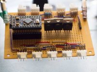
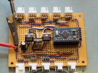
Partially soldered, just checking the parts fit where planned.
3LhAozBm.jpg

Fully built. Testing power up.
zic0fc0l.jpg

It worked first time! No shorts or issues of any sort. It was quite surprising not to have to debug it at all.
 
Associate
OP
Joined
7 Jan 2009
Posts
163
Associate
OP
Joined
7 Jan 2009
Posts
163
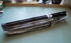
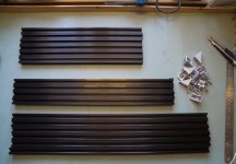
Guess what arrived!!! We have extrusion!

cqcipp9m.jpg

All arranged nicely.
6 x 400mm for the width.
4 x 500mm for the height. - These may end up being 450mm.
4 x 600mm for the length. - I will likely cut these down to 500mm.
xHkDbVnl.jpg

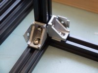
Immediately found a problem with the corner pieces I had. They came with no washers, so when tightened fully they did not compress enough to keep things in place. In the below pic I used some spare corner brackets as washers just to make sure everything else fitted. Did I have any M5 washers to hand? nope, hundreds of M3 and M4 but no M5. Another RS order!
x3F7OSll.jpg

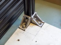
So with the washers arrived here it is mocked up with a scrap board showing where the base plate will be mounted.
XIQQXbnl.jpg

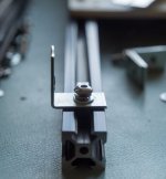
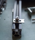
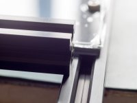
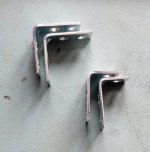
Then I went to use the corner brackets. Another issue! They stood proud of the extrusion. Floating panels is not the look I'm going for so I had to find a solution to that.
px7EfDYl.jpg

A quick bit of dremmel later the holes are now slots. Excellent. Just need to order some more of these as they will be used for all 7 of the side panel pieces.
enrWIvzl.jpg
 
Associate
OP
Joined
7 Jan 2009
Posts
163
Just went to buy some more right angle pieces and thought I'd have a look at how much the 'proper' 2020 ones are. At the moment, considering international shipping is not reliable, I'm looking inside the UK only. The proper 2020 right angles would be £16 for 20 off (irritatingly I need about 30) or generics are £11 for 100 off. I will have to modify the generic ones slightly but for the money saving it's an easy decision.
 
Associate
OP
Joined
7 Jan 2009
Posts
163
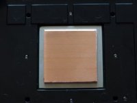
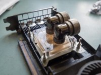
So a big of a different day today. Modding the VEGA56 card for watercooling. Looking at the price of waterblocks for this card was eye-watering and limited so I thought I'd put a spare CPU block to good use.

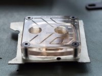
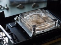
An EK Supreme HF.

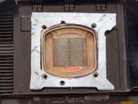
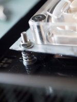
Sadly for me the stock mounts did not support the 64x64mm mounting holes of the Vega56 GPU/Memory cooler. So I had to make one from a piece of scrap steel. Not pretty but effective.

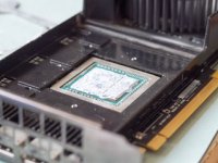
Firstly, a half naked pic of the GPU.
u7bd6vQm.jpg

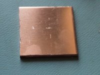
As you might be able to see the rest of the heatsink is higher than the core and memory die so I had to fashion a copper shim from a 3mm copper sheet.
rdg81egm.jpg

Copper shim fits perfectly! Even if there is a very slight scratch right in the middle. Careless me.
9xkUSHSm.jpg

Checking everything lines up.
vDqRGDfm.jpg

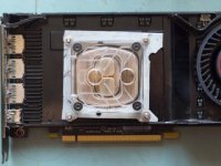
Waterblock fitted with it's new mounting hardware.
Bgsi8I4m.jpg

Not pretty, but fits.
a8P74PAm.jpg

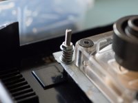
Had some spare springs laying around to even out the mounting pressure. I had envisaged using wing nuts but there wasn't enough clearance to the top of the block.
y4nlo1lm.jpg

Mounted.
2VkCRndl.jpg

Next step on this part is to figure out the routing for the tubing and what adjustments have to be made to the stock cooler cover. That needs to be able to go back on in some capacity to increase the effectiveness of the blower. Either that or I remove the blower and use a difference fan arrangement.
 
Associate
OP
Joined
7 Jan 2009
Posts
163
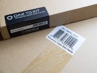
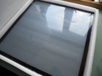
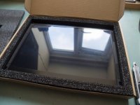
Big delivery from Overclockers.co.uk today. The tempered glass is in!

DOaEfXVl.jpg

Two of these beauties:
tBMSLlhl.jpg

And one of these:
cCCHmDil.jpg

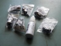
Also got a bunch of fittings and some dye.
Q5ybxS2l.jpg

Here is the dye looking very abstract art style.
FUfKot5l.jpg

Some nice right angle fittings for the GPU.
7Ld5hmPl.jpg

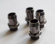
Some barbs because I'm not 100% on the loops yet and I didn't want to be left short on fittings.
AWAhgO8l.jpg

Managed to cut 70% of the aluminium to length today after some measuring up with the glass panels. Two of the three dimensions are sorted. Here's an example of the annoyingly small adjustment required to all six of the width extrusions. Just a few mm.
1rK3MAsl.jpg
 
Joined
30 Apr 2020
Posts
1
Location
Ireland
That's coming together very nicely Sam. It's refreshing (and exciting) to see a truly custom build!

Could you throw in the specs for the build please? I know you're opting for a Vega56 GPU but that's about it - nice workaround for the CP- I mean GPU block.

If you're going for a push/pull combo you can certainly opt for thicker rads because I know I would, I'm talking 60mm+ Speaking of which, have you considered what you're going to do for dust filtering on the intake fans?

Wishing you the best of luck in your build!

Cheers.
 
Associate
OP
Joined
7 Jan 2009
Posts
163
That's coming together very nicely Sam. It's refreshing (and exciting) to see a truly custom build!

Could you throw in the specs for the build please? I know you're opting for a Vega56 GPU but that's about it - nice workaround for the CP- I mean GPU block.

If you're going for a push/pull combo you can certainly opt for thicker rads because I know I would, I'm talking 60mm+ Speaking of which, have you considered what you're going to do for dust filtering on the intake fans?

Wishing you the best of luck in your build!

Cheers.

Thanks. This is my first ever custom case so lots of learning being done, which is very enjoyable.

Specs are as follows:
7800X - hopefully with an overclock once this gets done.
Gigabyte X299 AORUS Ultra Gaming Pro
32gb Corsair Vengeance LPX 2666Mhz
AMD Vega56
Samsung 960 250GB NVME
Samsung SM951 250GB NVME
Antec AX1200
Asus Xonar DX Sound Card (maybe, I've got it in a box somewhere so may as well use it).

The watercooling plan is as follows...
CPU Loop:
Block: EK Supreme HF
Rad: 420mm EK Coolstream XTC 55mm
Fans: Gelid Silent 14 x3 (tempted to get another three for push/pull)
Pump: EK DCP 2.2
Res: 150mm Tube (This may change depending on where they end up being mounted)

GPU Loop:
Block: EK Supreme HF with custom mounting bracket.
Rad: 360mm Generic approx 25mm thick. I've had it for years and it's a trooper.
Fans: Arctic F12 x3 (again might get another three)
Pump: D4 with custom speed controller (because it's so damn loud!)
Res: 150mm Tube (This may change depending on where they end up being mounted)

Dust filtering is a very good question. Something I've been considering for a the last few days. I would like to build some custom magnetic filters for the intake fans. We'll see how that goes, more to come when the parts arrive.
 
Last edited:
Associate
OP
Joined
7 Jan 2009
Posts
163
Running the numbers there could be anywhere between 9 and 20 fans in this build. I feel a custom fan controller coming on!
 
Associate
OP
Joined
7 Jan 2009
Posts
163
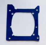
Progress:
Testing out the spray paint colours on the GPU mounting bracket. The blue looks brilliant! It also looks to be a very good match to the water dye.
AdvTh1Sl.jpg
FUfKot5m.jpg

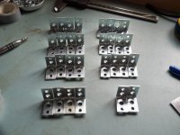
The L brackets needed trimming as they overhang the extrusion a little. Not too many to cut though!!!
an8Yikql.jpg

Before and after. All cut by hand saw.
2jDOZkel.jpg

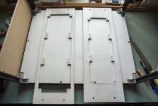
Also, in between rain showers I managed to prime two of the side panels. One takes the 3 x 140mm radiator and the other takes the 3 x 120mm radiator.
UDCCMaEl.jpg
 
Associate
OP
Joined
7 Jan 2009
Posts
163
Couple of things in the post today.

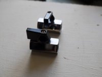
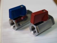
The valves for the drainage ports. Only £3.50 on eBay for two. Seems better than some of the other more expensive offerings. I also may spray the black handles.
SEGukxkm.jpg

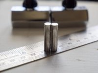
Some magnet. Hopefully will get to use these on the intake filters.
SvtWR4Lm.jpg

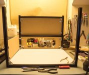
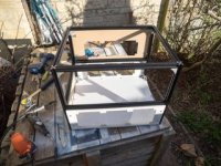
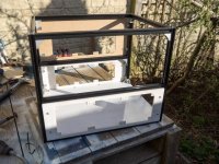
First time putting the whole frame together with everything cut to length and most of the side panels cut. Starting to take shape!
aCThqP2m.jpg

pFRpP0Ml.jpg
 
Associate
OP
Joined
7 Jan 2009
Posts
163
Okay. change of plan on the colour scheme.

Going for a bi-colour theme now. Red and Blue. More to come later...
 
Back
Top Bottom