

Associate
- Joined
- 31 Jul 2012
- Posts
- 1,016
- Location
- Cheshire
R-Pod MKII Racing Simulator:
This is a condensed version of my build log for the R-Pod MKII. I will try and show the basic flow of the project and some of the key stages and techniques used to create the final product. It may provide some more general ideas for other home projects people have as it goes into the construction of windowed panels for more interesting project builds.
R-Pod MKII video tour:
Tools and Materials:
Materials:
Wood Strips
Backing board
Hardwood
Screws / Bolts
Seat runners
Rubber sheet
Carpet
Blackboard vinyl
Acrylic
Artwork
Cabling (power strip / USB + hub / DVI / Displayport / speaker)
Velcro
Aluminium plate, strips, edging
Mesh
Leather material
T molding
Paint and Varnish
Desk grommet
Accessories (tow hook / extinguisher / badge)
Glues (wood / epoxy / contact)
Shelf supports
LEDs
Wire Switches Connectors
Tools:
Workbench
Clamps
Router
Jigsaw
Power drill / driver
Foam roller
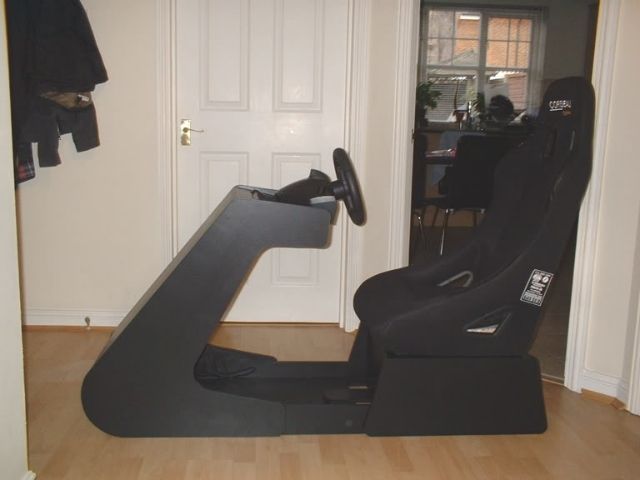
MKI of the R-Pod was built some years ago when I was first starting out on project builds. This was the basic style and at the time I was very happy with it:
As I completed other projects and my skills became better, I undertook to update them with better designs.
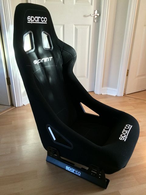
The first thing to source was a seat. I'd found the previous bucket seat I had really comfortable, much more so than a regular car seat so I bought something low / mid range - the Sparco Sprint:
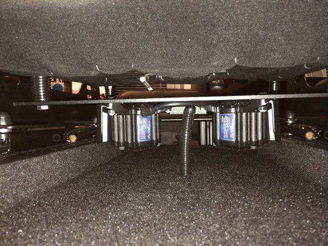
As I wanted to include tactile feedback, Buttkickers and an amp were obtained (these were actually bought for me by someone who left my team at work, as a thank you!):
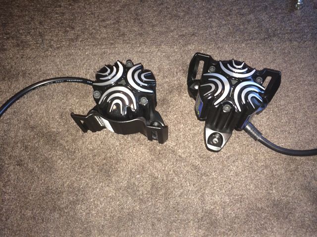

These were attached to a 4mm thick aluminium plate and bolted onto the underside of the seat. The result was very clear vibration sent through the metal frame of the seat.

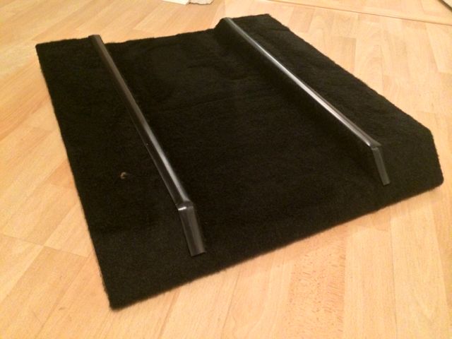
The base that the seat would attach to was then fabricated. Channels were made to ensure sufficient clearance for the Buttkickers:

This was then covered in automotive carpet with black T-Molding used to tidy up any exposed MDF edges:
Flexible sheathing and a project box were used to tiy the cabling and visible bolts. Seat runners were also fitted to allow the seat to more fore and aft:
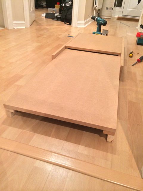
The base was then constructed with a slight drop included towards the front to ensure a more comfortable seating position when my feet were not resting on the pedals:
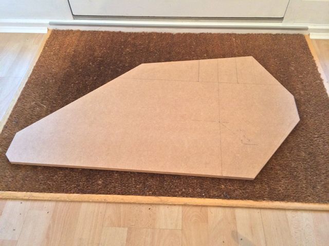
Next up was the shifter pod to be located to the side of the Rig. After a few hours of sitting and measuring, I came up with the appropriate positioning of the shifter. I then defined the design profile for it:
This was cloned twice to give 3 panels in total:

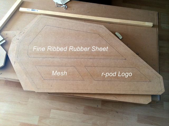
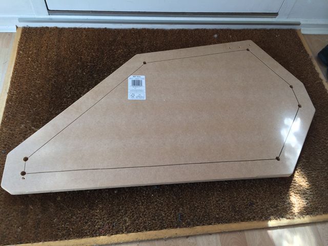
Working with the panel, I drew out the window sections I wanted to include in one of the sides:
Holes were drilled to allow the windows to be cut out with a jigsaw:
The windows were rough cut with a jigsaw:
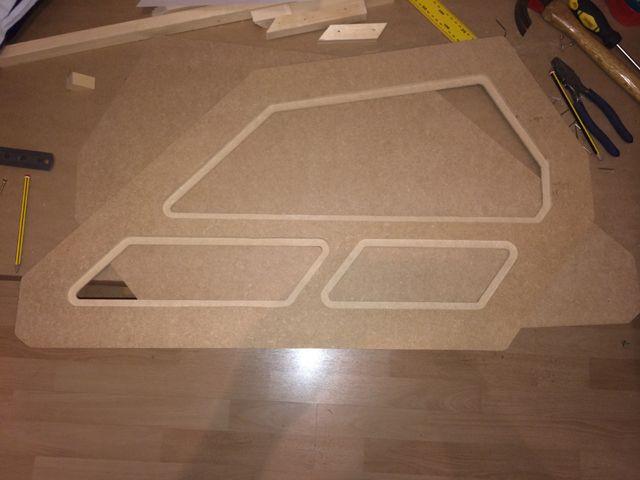
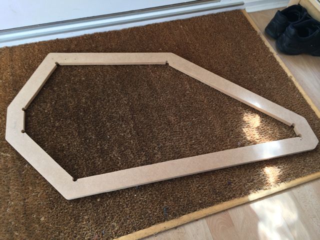
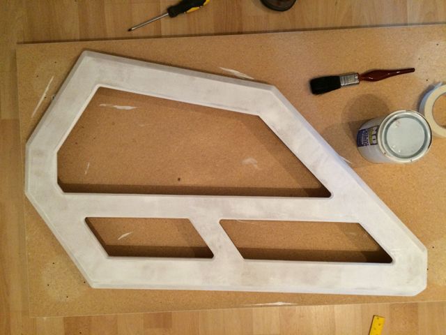
Wooden guides were nailed to the lines which defined the windows and a flush trim router bit used to obtain a clean and straight finish:
A chamfer bit was used to create the beveled edges on the outer surface and the inside of the widow sections:
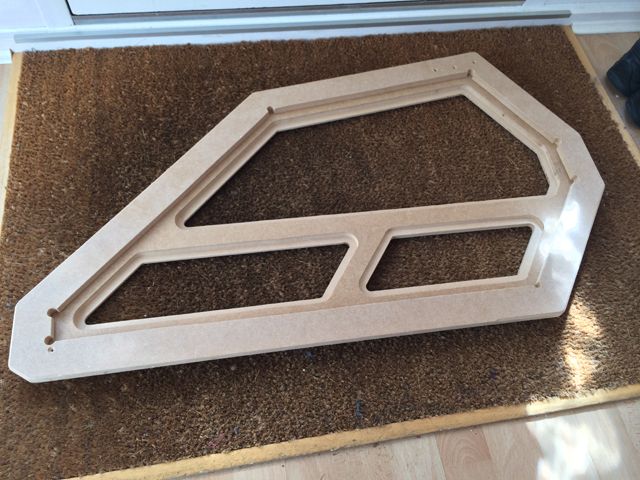
A rabbet bit was used to rout the inside of the panel to allow the materials / inlays to sit in them:
The top plate which would contain the shifter was then cut:
The window for the inner panel was then drawn and cut out:
The remaining pieces for the pod were then cut:
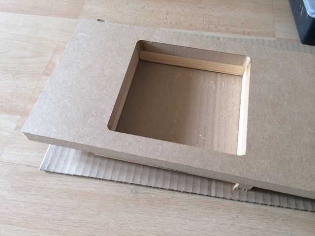
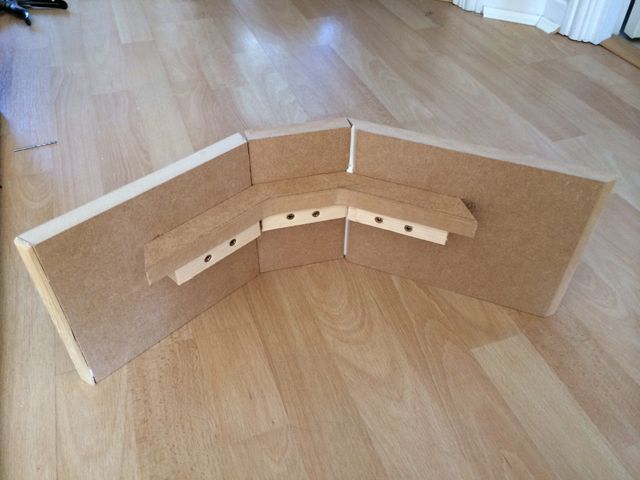
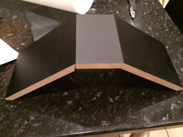
Internal bracing was fabricated to ensure the panels remained stable:
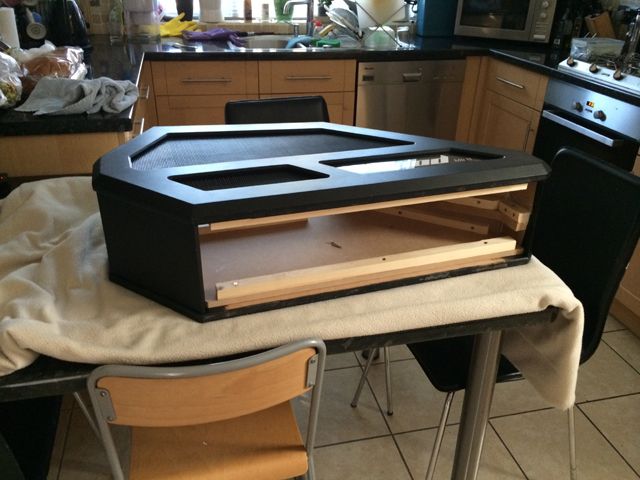
The outer panel is actually made from 2 pieces of MDF - one 18mm and one 12mm. The 18mm was used for the main outer section with the 12mm one used for the inner. In order to allow finishing and leave access to the windows, a further cut had to be made:
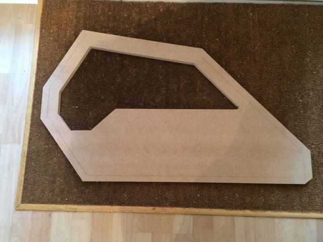
This picture shows the access to the windows from the inside:
With the cut out section back in place:
Approaching it like this allows the whole panel to be painted in isolation with the window inserts fitted later - this ensures a really nice and clean finish.
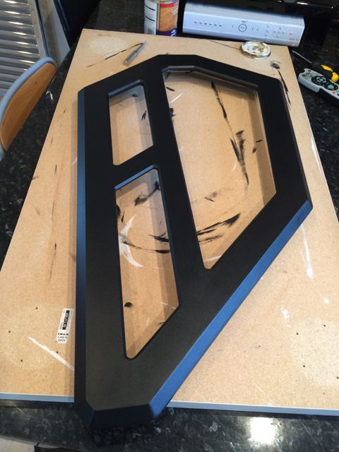
Some of the panels were then filled and sanded with Blackboard vinyl attached to them:
The panels themselves were then filled, sanded, undercoated, painted and varnished:

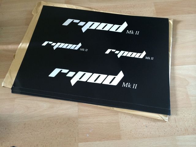
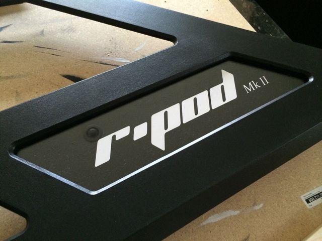
I designed some artwork and had it printed. This was attached to backing board and covered with 3mm cast acrylic:
Automotive mesh and ribbed rubber sheeting was inserted into the other 2 windows:
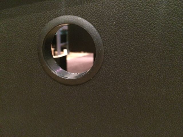
For the inside face, leather vinyl was used and hole cut out to access the mechanism on the shifter which allows the selection of sequential of H-Pattern shifting:
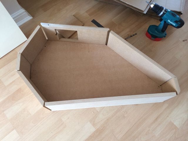
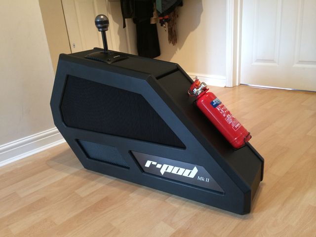
The whole unit was then assembled from the inside, out:
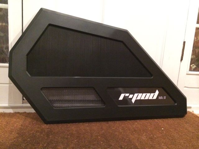
Completed shifter pod:
This is a condensed version of my build log for the R-Pod MKII. I will try and show the basic flow of the project and some of the key stages and techniques used to create the final product. It may provide some more general ideas for other home projects people have as it goes into the construction of windowed panels for more interesting project builds.
R-Pod MKII video tour:
Tools and Materials:
Materials:
Wood Strips
Backing board
Hardwood
Screws / Bolts
Seat runners
Rubber sheet
Carpet
Blackboard vinyl
Acrylic
Artwork
Cabling (power strip / USB + hub / DVI / Displayport / speaker)
Velcro
Aluminium plate, strips, edging
Mesh
Leather material
T molding
Paint and Varnish
Desk grommet
Accessories (tow hook / extinguisher / badge)
Glues (wood / epoxy / contact)
Shelf supports
LEDs
Wire Switches Connectors
Tools:
Workbench
Clamps
Router
Jigsaw
Power drill / driver
Foam roller
MKI of the R-Pod was built some years ago when I was first starting out on project builds. This was the basic style and at the time I was very happy with it:

As I completed other projects and my skills became better, I undertook to update them with better designs.
The first thing to source was a seat. I'd found the previous bucket seat I had really comfortable, much more so than a regular car seat so I bought something low / mid range - the Sparco Sprint:

As I wanted to include tactile feedback, Buttkickers and an amp were obtained (these were actually bought for me by someone who left my team at work, as a thank you!):


These were attached to a 4mm thick aluminium plate and bolted onto the underside of the seat. The result was very clear vibration sent through the metal frame of the seat.

The base that the seat would attach to was then fabricated. Channels were made to ensure sufficient clearance for the Buttkickers:

This was then covered in automotive carpet with black T-Molding used to tidy up any exposed MDF edges:

Flexible sheathing and a project box were used to tiy the cabling and visible bolts. Seat runners were also fitted to allow the seat to more fore and aft:

The base was then constructed with a slight drop included towards the front to ensure a more comfortable seating position when my feet were not resting on the pedals:

Next up was the shifter pod to be located to the side of the Rig. After a few hours of sitting and measuring, I came up with the appropriate positioning of the shifter. I then defined the design profile for it:

This was cloned twice to give 3 panels in total:

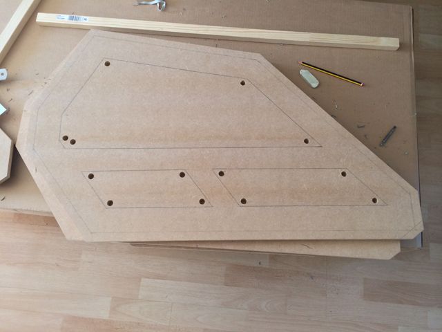
Working with the panel, I drew out the window sections I wanted to include in one of the sides:

Holes were drilled to allow the windows to be cut out with a jigsaw:

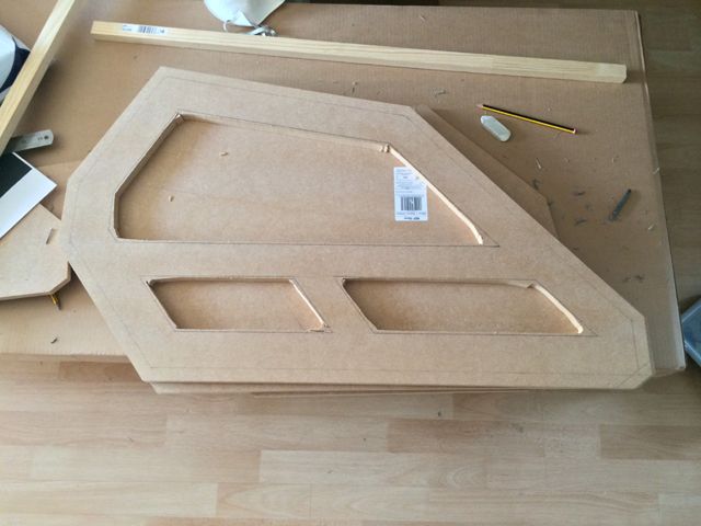
The windows were rough cut with a jigsaw:

Wooden guides were nailed to the lines which defined the windows and a flush trim router bit used to obtain a clean and straight finish:

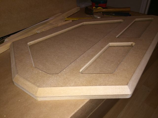
A chamfer bit was used to create the beveled edges on the outer surface and the inside of the widow sections:

A rabbet bit was used to rout the inside of the panel to allow the materials / inlays to sit in them:

The top plate which would contain the shifter was then cut:

The window for the inner panel was then drawn and cut out:

The remaining pieces for the pod were then cut:

Internal bracing was fabricated to ensure the panels remained stable:

The outer panel is actually made from 2 pieces of MDF - one 18mm and one 12mm. The 18mm was used for the main outer section with the 12mm one used for the inner. In order to allow finishing and leave access to the windows, a further cut had to be made:

This picture shows the access to the windows from the inside:

With the cut out section back in place:

Approaching it like this allows the whole panel to be painted in isolation with the window inserts fitted later - this ensures a really nice and clean finish.
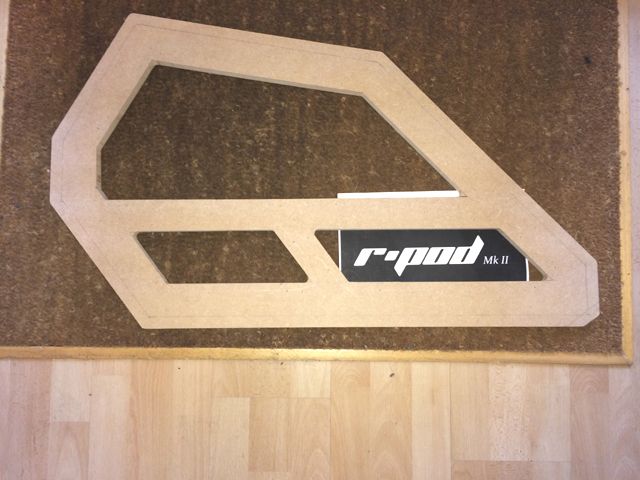
Some of the panels were then filled and sanded with Blackboard vinyl attached to them:

The panels themselves were then filled, sanded, undercoated, painted and varnished:


I designed some artwork and had it printed. This was attached to backing board and covered with 3mm cast acrylic:

Automotive mesh and ribbed rubber sheeting was inserted into the other 2 windows:

For the inside face, leather vinyl was used and hole cut out to access the mechanism on the shifter which allows the selection of sequential of H-Pattern shifting:

The whole unit was then assembled from the inside, out:

Completed shifter pod:


")
