How to repair a Dead Dell 3008WFP Monitor

Associate
Joined
21 Jun 2016
Posts
4
thanks for this guide!

halfway through the repair, wish i could say its been easy but its definitely been a learning experience.

im at the point of soldering in the replacement diode, just a quick question -- the original diode had a ceramic black ring on its third leg (a jumper or something?), does the replacement diode need one of those or just put it in as is?
 
Associate
OP
Joined
13 Jun 2007
Posts
1,057
Location
Dorset
thanks for this guide!
just a quick question -- the original diode had a ceramic black ring on its third leg (a jumper or something?), does the replacement diode need one of those or just put it in as is?

Does it come off the old diode?
It's been many a moon since I did mine so I cannot remember whether it came off of not. If is does put it on the third leg of the new diode. My guess is it does not come off as I would have mentioned it in my original post.


.
 
Associate
OP
Joined
13 Jun 2007
Posts
1,057
Location
Dorset
didnt come with the new diode

i tried to take it off the original but it was glued and i only ended up crushing it.

That make sense as I would have mentioned it in the O/P. Just solder the new diode in place and you should will be good to go, but wait a bit hopefully someone who has repaired one recently will chime in and confirm one way or the other....


.
 
Last edited:
Associate
Joined
21 Jun 2016
Posts
4
put in the new diode as it was (no extra bits), my soldering job was pretty poor so half expecting to have bodged it up, but its back on & working like a charm..

thanks again for this guide! i've got 2 of these monitors, so expecting the other one to do the same at some point too..
 
Associate
Joined
21 Jun 2016
Posts
4
my soldering job would honestly be laughed at and it worked fine. i found the desoldering pretty difficult, first time i'd done that on a pcb. but i probably also didnt have the best tools for the job. my solder tip might have been too thin and my desolder wick too wide making it harder than necessary, combined with doing it hunched over on the floor at 2am. one of those things though, if you go slow and steady, any spaz can do it. living proof right here.

as someone else said, the hardest part by far is removing the bezel. you need to go at it hard, like you're willing to break it.
 
Last edited:
Associate
OP
Joined
13 Jun 2007
Posts
1,057
Location
Dorset
put in the new diode as it was (no extra bits), my soldering job was pretty poor so half expecting to have bodged it up, but its back on & working like a charm..

thanks again for this guide! i've got 2 of these monitors, so expecting the other one to do the same at some point too..

Great!! Glad it worked

.
 
Associate
Joined
27 Jun 2016
Posts
1
Hi,

I just joined the forum specifically so I could say THANK YOU. This post is gold. Another happy Aussie with a working monitor again.

Bloody frustrating repair though, but take it slow and it's fine.

The only thing I would add is that removing the front bezel is actually a lot easier than people think. You just need to lift up and towards the centre from the INSIDE of the bezel (hook fingers under it where it meets the LCD and pull hard!)

Exactly like this guy is doing here at around the 40 second mark.

https://www.youtube.com/watch?v=89Z8-eYknmc

Thanks again Internets! You saved my village!
 
Associate
Joined
5 Jan 2015
Posts
9
Lot's of Aussie's encountering this, maybe they got the cheaper batch?

Have got a 3007WFP that's still going strong 10yrs later. Have just replaced it with the Del 43" 4k monster. Same DPI, more screen real estate.
 
Associate
Joined
17 Sep 2016
Posts
1
Thank you so much embalse, for this tutorial.

I have 2 of these monitors and I have changed the psu once on both of them. 1 died last week and I found this post ordered the part from farnell, I now have my monitor working again and 2 spare powersupplys.

Thank you so much. Total cost of the repair for 3 psu's was around £11 inc shipping. what a bargain. All 3 had the same issue once tested with a multimeter.
 
Associate
Joined
23 Oct 2016
Posts
1
I joined to say thank you embalse. I repaired my monitor this last week, and purchased my diodes from Ebay for under $10. I got to the point where I needed to desolder and instead I gently lifted the heat shield and left the two diodes in place and with a long shafted screwdriver unscrewed them from the shield, with only two places to remove solder on the shield. Then on the damaged diode diode D22, I unscrewed it and desoldered leaving the shield in place, and as D_Monolith stated there is a screw with a nut on the other end to contend with. I manged the whole task by desoldering only 5 points. I used toothpicks to clean up any solder and ran toothpicks between solder joints to clean up any possible mess on the PCB. Toothpicks are great to push through holes in PCB boards while you've got the iron in it. I didn't have braid so I had to be inventive.
I am using my Dell monitor right now as I type!
Massive thank you shout out from Queensland Australia.
 
Last edited:
Soldato
Joined
20 Jun 2011
Posts
3,675
Location
Livingston
7_zps86865231.jpg

For a second I thought that was a McDonalds hash brown you had at the back there lol.

Great fix, good of you to share it.
 
Associate
Joined
26 Nov 2016
Posts
1
Hi. I'm from the Netherlands, and just joined to say THANKS to Embalse and all people who found the real solution to this problem!

My 3008WFP died just over 3,5 years ago, after about 5 years in service. I quickly found out it had to be the power supply, but couldn't find anything to fix it. Since it was over 5 years old it was also out of warranty. I found a similar topic as this one but most messages said things about dying again after several minutes to days. So I didn't dare to try to fix it. So I just bought a new U3014, and put this one aside. Now my U3014 went weird after only 3,5 years in service (WTF? probably the motherboard since it doesn't display the settings menu correctly), and ofcourse Dell won't help me since it's just out of warranty.
Now I found this topic and it really encouraged me to finally try to fix it. I simply don't have any money to buy a new monitor (and cheap ones doesn't fill my requirements) but this should be a cheap fix, and I know my way around electronics since I was a kid, so this should be easy for me. I'm so happy I didn't put this one with the trash!

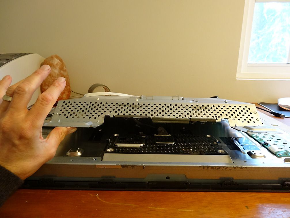
Ofcourse getting the bezel off was the hardest part. Took me about 45 minutes to open the damn thing alone, lol.

20161112_162430.jpg


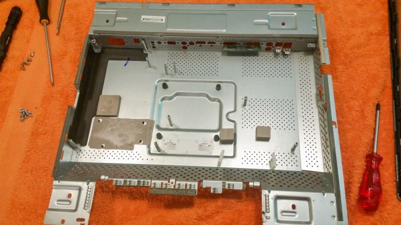
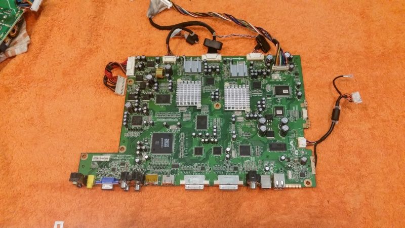
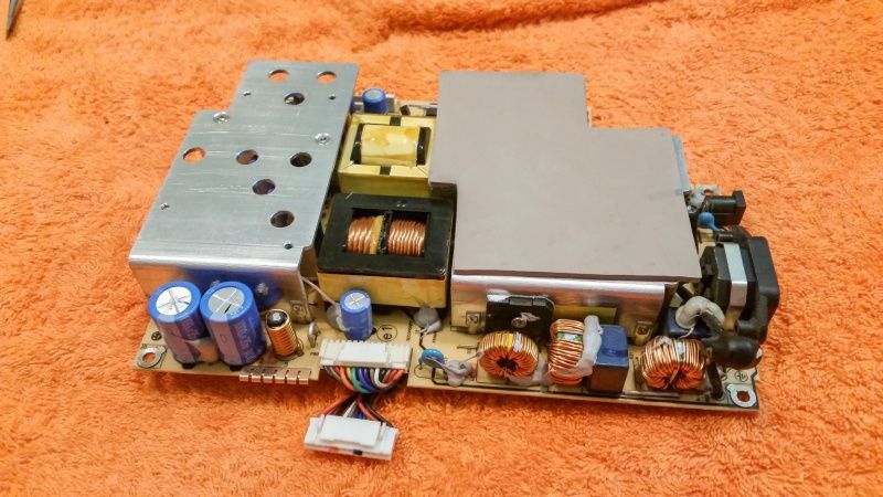
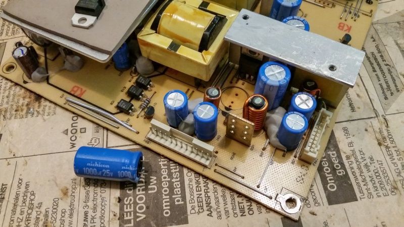
Following embalses steps was easy to get the power supply out. It came out easy. I also removed the motherboard to clean it and remove any dust, which was pretty neccessary. Along the way I also removed the USB-reader part to clean it, just as anything else.

20161112_190014.jpg


20161112_190021.jpg


20161112_192927.jpg


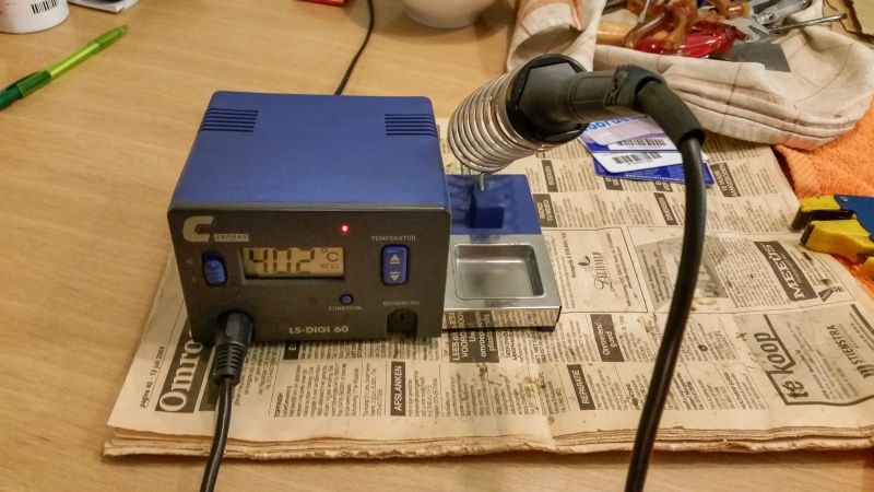
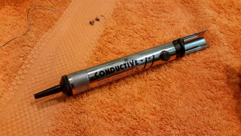
As said I'm an electronics guy and I have a good solder thing, which can be set between 200 and 450 degrees, and a 3 mm tip. I also have a desolder-pump, almost never used.

20161112_193347.jpg


20161112_193359.jpg


I don't have desolder-wire because I never needed it, and that turned out to be a problem. Took me hours to remove the solder, but finally it worked out... using a large rubber boat deflating pump which sucked way harder then my desolder-pump :D I first tried not to remove the first heatsink with 2 things on it, but it turned out to be the best way to remove it anyway. BUT I did it another way. I first removed the screws from the 2 things on the heatsink, then desolder only the heatsink, and finally desolder the 2 things one after the other, at last screwing them back to the heatsink. This was due to the lack of desolder-wire.

20161112_204803.jpg


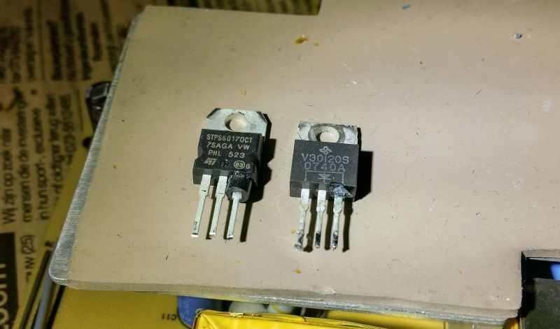
The new one on the left, ordered in the Neterlands, but probably came from Farnell. On the right the old diode.
As you can see I could pull off the black ring and glued it to the new diode. I don't know if it's really neccessary, but there's a reason it's there and all other things have them as well so I thought it was a little thing to do.

20161112_211301.jpg


I found out it was much easier to desolder one large cap then freaking around with tools to remove and put back on the nut on the back of the dead diode.

20161112_211555.jpg


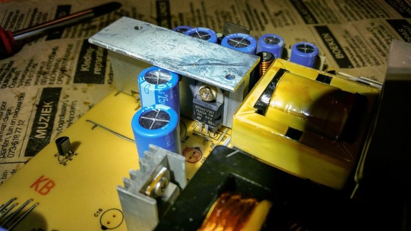
The new STPS60170CT in place!

20161112_214013.jpg


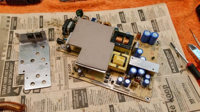
Putting everything back together, I also bought new alu tape and put it on it so now it's better as new. I had some CPU thermal paste which I also used on the heatsinks.

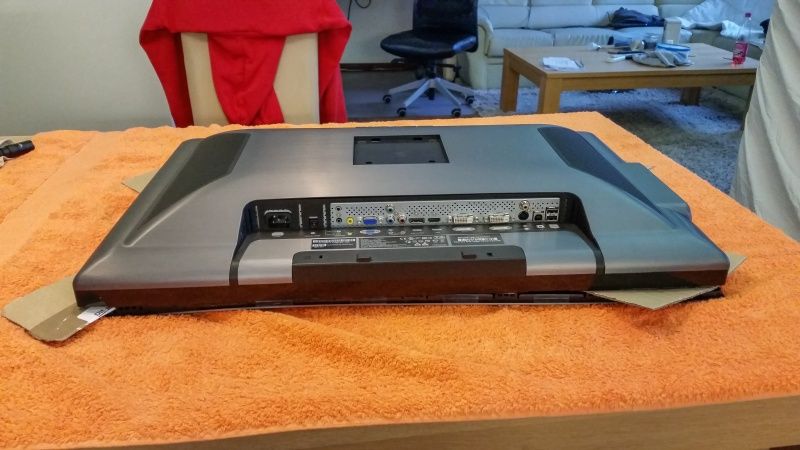
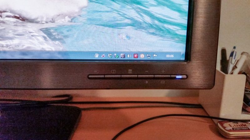
And finally, ofcourse before putting the bezel back on, test it! Yay it worked! Here it's back in service :)

20161113_000633.jpg


Total cost: 17 euro for 2 diodes STPS60170CT incl shipment, 10 euro for the alu tape. So less then 30 euro's total. Not even comparable to a new monitor!

Now we're 3 weeks later and it still works like it's new! So again, thanks Embalse and all others who made this work out.
And Dell, well, I'll never buy anything from Dell again... but for now I'm happy!
 
Soldato
Joined
13 Mar 2004
Posts
4,712
Location
Norwich
Another one :D great pictures and write up by the way!

I fixed mine back on 29th Aug 2014 and it is still sitting here today working just fine :)
 
Associate
OP
Joined
13 Jun 2007
Posts
1,057
Location
Dorset
Hi. I'm from the Netherlands, and just joined to say THANKS to Embalse and all people who found the real solution to this problem! My 3008WFP died just over 3,5 years ago, after about 5 years in service.........................


Hey glad you fixed it.
Thanks for contributing and sharing. Great pictures!!


.
 
Associate
Joined
15 Feb 2017
Posts
1
Location
UK
Hi there,

Followed the instructions and my monitor is switching on, but I have all these funny coloured lines on the screen. Any ideas? The screen looks like it is cracked when switched on.
 
Associate
Joined
4 May 2017
Posts
1
As with everyone else, I am indebted to Embalse and others who discovered the problem and documented the remedy so completely.

As an electronics design engineer with some 40 years experience I can perhaps shed some light on the deeper technical details of the fault and the repair.

The original V30120S diode is a single 30A 120V Schottky rectifier with its cathode connected to the centre leg and its anode connected to both outer legs. Both outer legs are also connected by a short wire jumper on the PCB. The ferrite bead found on the right-hand leg will have been intended to reduce EMI generated when the diode turns off on each cycle of the switch-mode power converter - but is in fact rendered inoperative because the wire jumper to the left-hand leg effectively shorts it out.

The recommended replacement STPS60170CT part is in fact a dual Schottky rectifier with the anode of each diode connected to an outer leg and the cathodes connected in common to the centre leg. Despite being a dual diode its internal connections are such that it is fully compatible - and has the advantage that the wire jumper between the outer legs on the PCB results in both diodes being connected in parallel - effectively giving a part rated at 60A and 170V - a substantial upgrade on the original diode current and voltage ratings.

Furthermore (at the risk of a slight over-simplification) the parallel connection means that the current that originally flowed in the single diode will now be shared more or less equally by each diode - which will in turn means that each diode will have a lower forward voltage drop when conducting - which should give a useful overall reduction in the heat generated through conduction losses. The result is a substantially higher rated part running cooler - both of which should greatly improve reliability.

If the ferrite bead can be removed intact from the failed device it should sensibly be installed on the CENTRE leg of the replacement STPS60170CT part - where it can do its intended job. If the bead is left off, the EMI signature may be a little higher, but should be no worse than with the original diode.

My guess is that the circuit was in fact originally designed to use a dual common-cathode diode but that the V30120S single diode was later substituted - perhaps to save costs. The reason the ferrite bead was placed on an outer leg remains a mystery and looks to simply be a production error. It is unclear if the V30120S device is under-rated for its role in the circuit or if the problem is that the part used in production is just of sub-standard quality.

What is clear is that the problem represents an "epidemic" design or production fault and that Dell do themselves no credit by pretending otherwise. In my country (New Zealand), such a problem is covered under consumer protection legislation, regardless of what warranty period is stipulated by the manufacturer - if it is "reasonable" to expect a longer service life for the type of product involved. It's arguable how long an expensive "flagship" monitor like this should last, and I'm guessing that in 2017 we are now at a point where a 2008 model monitor might be regarded as having reached the end of its reasonably expected life, but properly designed electronics intended for "professional" use should last longer than that - and if it weren't for this epidemic fault the 3008 monitor almost certainly would.

Similar comments apply to Dell's attitude to the epidemic fault evident with the Dell 2709Wfp monitor (I have personally had three such monitors fail in an identical manner) - although in that case the problem is due to the use of a sub-standard "Elite" brand capacitor on the rectified mains DC bus. Fortunately the Dell 3008WFP was built using good quality capacitors from reputable Japanese manufacturers (Rubycon and Nichicon) so doesn't suffer from that problem.
 
Associate
OP
Joined
13 Jun 2007
Posts
1,057
Location
Dorset
As with everyone else, I am indebted to Embalse and others who discovered the problem and documented the remedy so completely.

As an electronics design engineer with some 40 years experience, I can perhaps shed some light on the deeper technical details of the fault and the repair........


Hey, Thanks for the detailed explanation regarding this issue.


.
 
Associate
Joined
7 Feb 2003
Posts
1,229
My 3008WFP Monitor just died today.:(

Decided not to go ahead with the repairs to the PSU/diode as outline in the guide as it almost 9 years old.

I have not kept intouch what is happing with monitors, just looked and it is like a minefield with all the different options now.

It would seem that new screens will be arriving soon on 4K, UWide, HDR and 200hz +, G-Sync, Free-Sync 2

So just purchase a cheap monitor 1440P and wait for these new monitors with to come out over the next year 2018

Thanks

Simon
 
Last edited:
Back
Top Bottom