

In this tutorial I will be modifying a Blue LED Xilence 120mm fan into a Orange LED Xilence 120mm fan.

I used:-
4x Orange Super Bright 5mm LEDs (worth about 40p)
Soldering iron and thin solder (nicked from work)
Some scrap wire (from a telephone extension cable)
A point thing on my penknife.
12v power source (nicked from work)

On this image you can see that the LEDs have one long leg (Anode +ve) and one shorter leg (Cathode -ve). You can also see that the Anode has a smaller metal element inside the LED body.

On my fan the LEDs sat inside a 5mm hole and simply required a bit of force on the rounded lens side of the LED and they just popped out. So I did this with all 4.

Here's an extracted LED

The wiring of my fan, like my other LED fan consists of 4 spokes of wiring coming out of the hub of the fan. Each spoke is supplied by a single resistor stepping down from the 12v source at the centre. The resistors in my fan are 510 ohm which is fine for any colour LED.
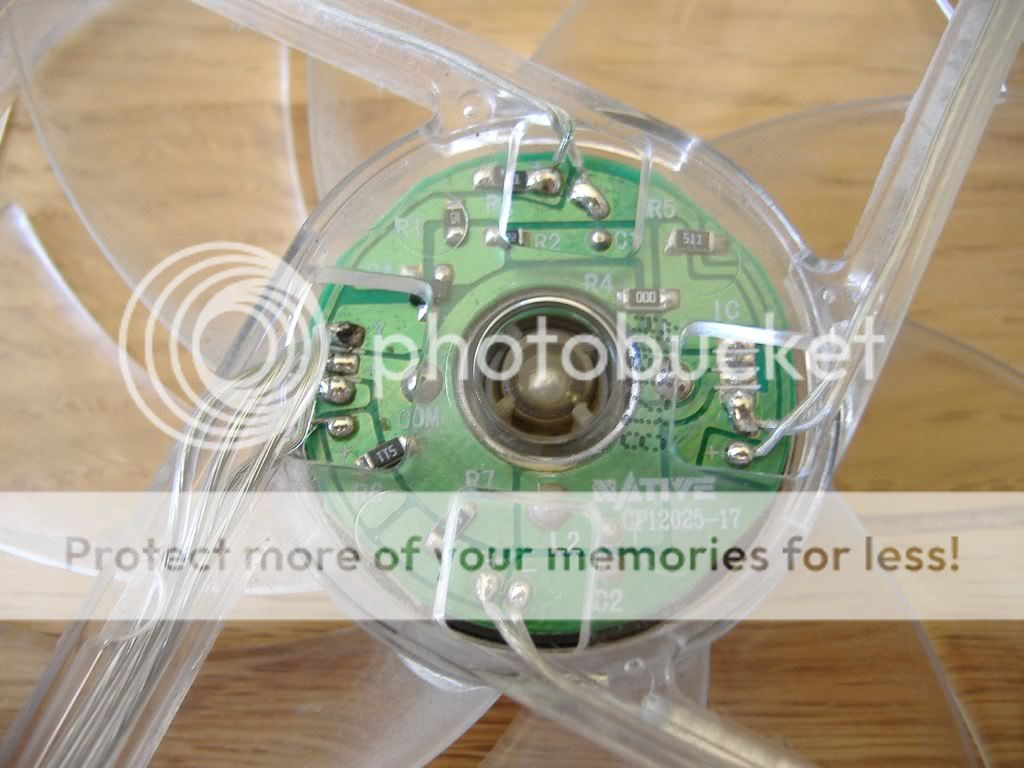
I could also see which wire was +ve because Xilence had thoughtfully marked it on all spokes for me. I also coloured in the +ve wire with a red marker just to make it easier for me to identify.
So now to trimming off the existing LEDs. Just snip them off and discard, keep as appropriate. I made a bit of a mistake and trimmed all LEDs back, forgetting that the wires would be too short. In hindsight I would probably just stick the full size LED in the hole and solder the wires to it directly, trimming down afterwards.
Next step is to bare a few mm of wire from the +ve and -ve wires (no pic)
So now onto soldering. Preparation is pretty important. It's a good idea here to pre-tin the bare wire and LED leg.

Heat the bare wire/LED leg a little with the iron and allow some solder to melt onto the subject. This cleans and removes impurities from the surface and allows a much stronger and electrically sound joint to be produced.
Soldering the LED to the wire.
Holding the LED with something introduce the tinned wire to the leg of the LED and introduce some heat with the iron, and feed a little solder into the joint as it warms up. Remove heat and hold until the solder solidifies. Plenty of tutorials in soldering available on youtube if you are unsure.

And soldering the other leg.

Do the same for all four and you should be good to test. Wire up the fan to a 12v source, such as a power brick like mine or any 9v to 12v power brick.

Pop the LEDs into the fan.

And revel in it's glory.

Night shots:


Additional notes.
There are different ways that manufacturers make their LED fans.
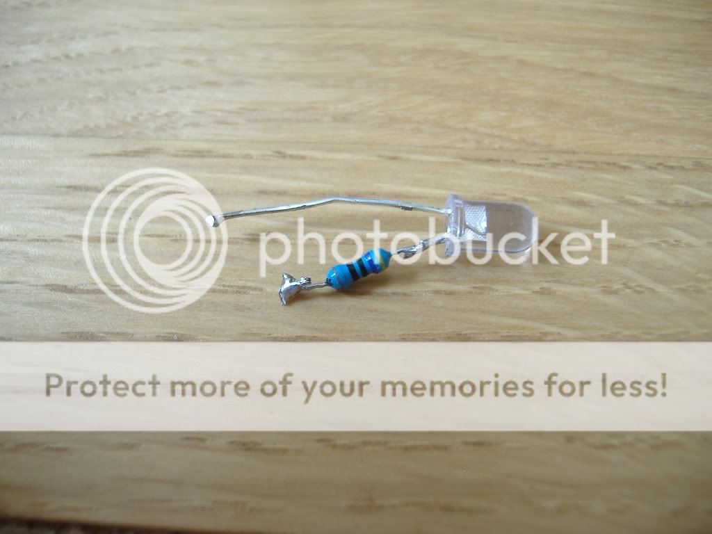
Here is an image of the hub of one of my other LED fans (A Coolermaster red LED fan)

This one uses traditional stripey resistors, in this case 470 ohm so will be a shade brighter than my 510 one on same LEDs. The higher the resistance the less the power that gets to the LED.
If your fan uses significantly lower resistance than 400 ohms when switching from blue/white to red/orange then you may need to install an additional resistor to bump it up a little.
Guide: Make something like this out of a standard fan. Click the image below.

I appreciate your feedback and will add to this guide as new information arises.
#First draft 07/08/2010.
I used:-
4x Orange Super Bright 5mm LEDs (worth about 40p)
Soldering iron and thin solder (nicked from work)
Some scrap wire (from a telephone extension cable)
A point thing on my penknife.
12v power source (nicked from work)
On this image you can see that the LEDs have one long leg (Anode +ve) and one shorter leg (Cathode -ve). You can also see that the Anode has a smaller metal element inside the LED body.
On my fan the LEDs sat inside a 5mm hole and simply required a bit of force on the rounded lens side of the LED and they just popped out. So I did this with all 4.
Here's an extracted LED
The wiring of my fan, like my other LED fan consists of 4 spokes of wiring coming out of the hub of the fan. Each spoke is supplied by a single resistor stepping down from the 12v source at the centre. The resistors in my fan are 510 ohm which is fine for any colour LED.
I could also see which wire was +ve because Xilence had thoughtfully marked it on all spokes for me. I also coloured in the +ve wire with a red marker just to make it easier for me to identify.
So now to trimming off the existing LEDs. Just snip them off and discard, keep as appropriate. I made a bit of a mistake and trimmed all LEDs back, forgetting that the wires would be too short. In hindsight I would probably just stick the full size LED in the hole and solder the wires to it directly, trimming down afterwards.
Next step is to bare a few mm of wire from the +ve and -ve wires (no pic)
So now onto soldering. Preparation is pretty important. It's a good idea here to pre-tin the bare wire and LED leg.
Heat the bare wire/LED leg a little with the iron and allow some solder to melt onto the subject. This cleans and removes impurities from the surface and allows a much stronger and electrically sound joint to be produced.
Soldering the LED to the wire.
Holding the LED with something introduce the tinned wire to the leg of the LED and introduce some heat with the iron, and feed a little solder into the joint as it warms up. Remove heat and hold until the solder solidifies. Plenty of tutorials in soldering available on youtube if you are unsure.
And soldering the other leg.
Do the same for all four and you should be good to test. Wire up the fan to a 12v source, such as a power brick like mine or any 9v to 12v power brick.
Pop the LEDs into the fan.
And revel in it's glory.
Night shots:
Additional notes.
There are different ways that manufacturers make their LED fans.
Here is an image of the hub of one of my other LED fans (A Coolermaster red LED fan)
This one uses traditional stripey resistors, in this case 470 ohm so will be a shade brighter than my 510 one on same LEDs. The higher the resistance the less the power that gets to the LED.
If your fan uses significantly lower resistance than 400 ohms when switching from blue/white to red/orange then you may need to install an additional resistor to bump it up a little.
Guide: Make something like this out of a standard fan. Click the image below.
I appreciate your feedback and will add to this guide as new information arises.
#First draft 07/08/2010.
Last edited:
")


