PWM to 3 pin fan converter circuit
Or how to finely control 3 pin fan/s with your 4 pin PWM motherboard/graphics card header and still get RPM feedback.
Have PWM control without the annoying tick noise that PWM fans sometimes create.
Drop me a message in trust, or post, if you want to ask me about making a circuit up for you. I've already made about 30 or 40 of these circuits for OcUK forum members.
The start of this thread deals with the development of the converter, it includes pictures and many videos and also explanations of what's going on electronically and may be a bit heavy for some.
However, this is the final product and this is what it does.
This is a version 2 I made for OcUK forum member.
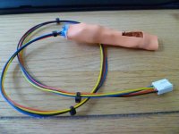
This one is designed for a Gelid Icy Vision and plugs into the graphics card to give the user fine control over their graphics card fan speed
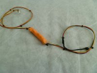
Here are two I made with 4 fan headers on the output.
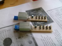
I fit a heatsink to the larger transistor as it can get a little warm when driving 2 or more fans.
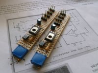
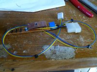
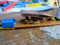
...and an older one I made for another OcUK forum member who wanted Molex for power. This one shows the inside of the heatshrink and one with the components in view, some of these components are now SMD and mounted under the board.
I can make these for a small cost to cover materials and postage and a bit for the time. Just drop me a trust message. I only make the latest versions these days, these come with all the trimmings and feature the best developments I've made on the circuit in the last two years.
---------------------------------------------------------------------------------------------------------------------------------
And now the original first post.
*****Due to Photobucket changing their third party website policy some of the images won't be working, if you want more detail let me know.*****
This thread details a small electronics project I'm currently developing to solve a problem I've had since building my rig a couple of years ago.
So many CPU coolers come with 3 pin fans yet we all have 4 pin headers on our motherboards, it's a very puzzling situation and in some cases motherboard just don't have any 3 pin control support. So we then have to ditch the fans and buy some 4 pin PWM ones. My Gigabyte motherboard has far better control over 4 pin fans than 3 pin fans, indeed Easytune6 or the BIOS won't even begin to control my 3 pin fans and I have to use Speedfan. At the moment I have the fan ramp up and down between two values 600RPM and 1000 RPM. It's not ideal.
I've always thought it'd be nice to be able to have the full 20-100% speed control of a 3 pin fan, just as we can have with 4 pin PWM fans, such as the Thermalright TY-140, Akasa Apache and Akasa Viper and other PWM fans.
Now I'm just too tight to buy more fans, considering I have so many 3 pin fans, just to get this fine control so I've always thought it'd be cool to have some sort of converter. It is, however a little tricky.
First thing's first. What is PWM? Pulse Width Modulation is a method of rapidly switching something on and off , varying the ratio of the time it is on related to off. The fan doesn't notice the switching because it's too fast, but other electronic items will.
Consider the following image with a PWM signal at approx 25,000 times per second.

It starts at 20% on/80% off, then goes to 50/50, rising to 80% on/20% off and finally 95% on/5% off. This is what a 4 pin PWM fan sees but cannot react fast enough to stop and start.
Consider again, if you will, the following DC voltage trace.

This is what a 3 pin fan sees.
How can we take the first image trace and convert it into the second but have that line vary depending on the percentage that our motherboard tells it to run at? To further complicate things motherboard/graphics card PWM is just a 5v signal and carries nowhere near enough power to do anything useful. It's just a control signal, not a current source.
Over in another thread Doyll was talking about an adaptor that Phanteks had sent him to do just that. My interest was piqued.
So I set about simulating a circuit in Multisim (circuit simulation software from National Instruments) and it didn't work. Not even close.
So after trying a few other ideas and realising that it's not going to be cheap or easy I came back to the original circuit, made a few adjustments, substituted my own transistor and got a really good result.
I threw a few components onto a board and tested.

This little circuit can drive a fan down to 150 RPM and all the way up to 100% of it's rated speed, just by the adjustment of the duty cycle. It's sensitive enough to change speed even with a small change to duty cycle, and what's even more useful is that I get full RPM feedback from the tach wire, something which was missing from so many other converter circuits.
This little circuit can be plugged into the motherboard PWM header and drive fans, or it can be plugged into a graphics card PWM header and drive fans. Basically as long as you shove a decently high Hertz PWM signal into the circuit it'll work.
So I've got more tests to come but this was one of my first. I hooked the circuit up to a 555 timer PWM circuit (on the left of the white board) and had it's tach output go to a counter circuit to light up the LEDs.
It's poor quality as it's recorded on my iPod.
I have hooked it up to my PC but light conditions were poor at the time so didn't record anything. I may upload a further video showing the amount of control I can have over the fan speed in a day or so. I am also hoping to load it up with 3 or so fans so I can to test it for capacity.
Thanks to Doyll for the images and help.
Or how to finely control 3 pin fan/s with your 4 pin PWM motherboard/graphics card header and still get RPM feedback.
Have PWM control without the annoying tick noise that PWM fans sometimes create.
Drop me a message in trust, or post, if you want to ask me about making a circuit up for you. I've already made about 30 or 40 of these circuits for OcUK forum members.
The start of this thread deals with the development of the converter, it includes pictures and many videos and also explanations of what's going on electronically and may be a bit heavy for some.
However, this is the final product and this is what it does.
- Control 3 pin fans directly from a 4 pin PWM fan header. That's CPU headers and GPU headers and any other PWM source in your PC.
- Plugs into a 4 pin PWM fan header and spits out a smooth voltage the other side so you can control 3 pin fans with as small as a 1% change in duty cycle.
- Has absolutely no PWM tick noise.
- You still get RPM feedback.
- It can control between 1 and 6 fans (depending on current rating), from less than 0.1A up to approx 1A via a adjustable screw.
- It will adjust speed based on the PWM signal it gets from your CPU fan header or the graphics card header.
- It uses less energy at low duty cycle. More efficient than many fan controllers.
- It can be tucked behind the motherboard or in a 5.25" bay.
- It can use Molex or fan header for power.
- It can drive fans down to 150 RPM and right up to maximum speed.
- It's home-made. Nothing quite like a ghetto mod

- It's safe. The circuit takes only a very small load from the PWM pin.
This is a version 2 I made for OcUK forum member.

This one is designed for a Gelid Icy Vision and plugs into the graphics card to give the user fine control over their graphics card fan speed

Here are two I made with 4 fan headers on the output.

I fit a heatsink to the larger transistor as it can get a little warm when driving 2 or more fans.

...and an older one I made for another OcUK forum member who wanted Molex for power. This one shows the inside of the heatshrink and one with the components in view, some of these components are now SMD and mounted under the board.


I can make these for a small cost to cover materials and postage and a bit for the time. Just drop me a trust message. I only make the latest versions these days, these come with all the trimmings and feature the best developments I've made on the circuit in the last two years.
---------------------------------------------------------------------------------------------------------------------------------
And now the original first post.
*****Due to Photobucket changing their third party website policy some of the images won't be working, if you want more detail let me know.*****
This thread details a small electronics project I'm currently developing to solve a problem I've had since building my rig a couple of years ago.
So many CPU coolers come with 3 pin fans yet we all have 4 pin headers on our motherboards, it's a very puzzling situation and in some cases motherboard just don't have any 3 pin control support. So we then have to ditch the fans and buy some 4 pin PWM ones. My Gigabyte motherboard has far better control over 4 pin fans than 3 pin fans, indeed Easytune6 or the BIOS won't even begin to control my 3 pin fans and I have to use Speedfan. At the moment I have the fan ramp up and down between two values 600RPM and 1000 RPM. It's not ideal.
I've always thought it'd be nice to be able to have the full 20-100% speed control of a 3 pin fan, just as we can have with 4 pin PWM fans, such as the Thermalright TY-140, Akasa Apache and Akasa Viper and other PWM fans.
Now I'm just too tight to buy more fans, considering I have so many 3 pin fans, just to get this fine control so I've always thought it'd be cool to have some sort of converter. It is, however a little tricky.
First thing's first. What is PWM? Pulse Width Modulation is a method of rapidly switching something on and off , varying the ratio of the time it is on related to off. The fan doesn't notice the switching because it's too fast, but other electronic items will.
Consider the following image with a PWM signal at approx 25,000 times per second.

It starts at 20% on/80% off, then goes to 50/50, rising to 80% on/20% off and finally 95% on/5% off. This is what a 4 pin PWM fan sees but cannot react fast enough to stop and start.
Consider again, if you will, the following DC voltage trace.

This is what a 3 pin fan sees.
How can we take the first image trace and convert it into the second but have that line vary depending on the percentage that our motherboard tells it to run at? To further complicate things motherboard/graphics card PWM is just a 5v signal and carries nowhere near enough power to do anything useful. It's just a control signal, not a current source.
Over in another thread Doyll was talking about an adaptor that Phanteks had sent him to do just that. My interest was piqued.
So I set about simulating a circuit in Multisim (circuit simulation software from National Instruments) and it didn't work. Not even close.
So after trying a few other ideas and realising that it's not going to be cheap or easy I came back to the original circuit, made a few adjustments, substituted my own transistor and got a really good result.
I threw a few components onto a board and tested.

This little circuit can drive a fan down to 150 RPM and all the way up to 100% of it's rated speed, just by the adjustment of the duty cycle. It's sensitive enough to change speed even with a small change to duty cycle, and what's even more useful is that I get full RPM feedback from the tach wire, something which was missing from so many other converter circuits.
This little circuit can be plugged into the motherboard PWM header and drive fans, or it can be plugged into a graphics card PWM header and drive fans. Basically as long as you shove a decently high Hertz PWM signal into the circuit it'll work.
So I've got more tests to come but this was one of my first. I hooked the circuit up to a 555 timer PWM circuit (on the left of the white board) and had it's tach output go to a counter circuit to light up the LEDs.
It's poor quality as it's recorded on my iPod.
I have hooked it up to my PC but light conditions were poor at the time so didn't record anything. I may upload a further video showing the amount of control I can have over the fan speed in a day or so. I am also hoping to load it up with 3 or so fans so I can to test it for capacity.
Thanks to Doyll for the images and help.

Last edited:


