You are using an out of date browser. It may not display this or other websites correctly.
You should upgrade or use an alternative browser.
You should upgrade or use an alternative browser.
**Dell PowerEdge T20 Mini Tower Server - Owner Thread**
- Thread starter StevenG
- Start date
More options
Thread starter's postsJust an fyi - after 3 months my chipset lost the plot and started rebooting the machine every 10 mins, but only with the network cable plugged in. Dell have replaced the mobo and currently working fine.
Hope this helps speed up your diagnosis if it happens to you.
Hope this helps speed up your diagnosis if it happens to you.
Associate
- Joined
- 20 Apr 2009
- Posts
- 1,269
Oh and Doug, let me know how you get on with the RAM.
So I ended up getting 2x8gb sticks of this
http://www.crucial.com/usa/en/ct102472bd160b
Working absolutely perfectly. Have also found another 4gb module in addition to the one that it came with, so have 24gb total in there now (2x8 + 2x4) all ECC 1600mhz. All good. Total spent on RAM for me is now £60.
My latest issue though... bought a pexsat32 card (the startech 2-port one that Dell recommends), and so far can't see it or the dries plugged into it. Not sure what's going on here, as it should be straight plug and play.
I did manage to get myself a RAID card on ebay though for a good price, so can always try that instead but need to flash it to IT mode first.
Questions for all you early adopters. I currently has a Proliant Microserver for the last 5_+ years and looking to by the T20 Xeo. For File Server/Storage and put some VMs on there. I currently have Windows 7 enterprise running without a monitor attached as I connect to the Microserver remotely.
Although I have the license key of Windows 7/10 Enterprise, I am thinking of going ESXi route rather than a Windows OS on the Actual Box. Can I run ESXi on a headless install without a monitor attached or am I better off running a Windows OS?
I also currently use Stablebit Drivepool, If I go the ESXi route can this drivepooling function bedone through ESXi or I have to stick with the Software option which is the Stablebit option.
Thanks in advance
Soldato
The ESXi console is all text based, so unless something is broken you would normally do everything remotely. We only plug a KVM into an ESXi server to fix a problem - they are headless otherwise.
ESXi will want to look after the HDs directly - I did turn up this thread here which discusses passing the HDs through to a VM with DrivePool : http://community.covecube.com/index.php?/topic/1423-esxi-hosting-of-drivepool-and-scanner/
ESXi will want to look after the HDs directly - I did turn up this thread here which discusses passing the HDs through to a VM with DrivePool : http://community.covecube.com/index.php?/topic/1423-esxi-hosting-of-drivepool-and-scanner/
Associate
- Joined
- 20 Apr 2009
- Posts
- 1,269
So I wanted an install of Ubuntu on mine, as well as a Plex server and of course for it to function as a NAS.
After spending a lot of time thinking about ESXI, I've ended up dumping that and going with UnRAID instead. Ticks all my boxes perfectly - completely headless, can install Plex (and loads, loads more) directly into it, and it effectively acts as a hypervisor, as you can install VMs inside it (so you can install Ubuntu from there, or Windows).
I'm dead happy with it so far.
Last edited:
The ESXi console is all text based, so unless something is broken you would normally do everything remotely. We only plug a KVM into an ESXi server to fix a problem - they are headless otherwise.
ESXi will want to look after the HDs directly - I did turn up this thread here which discusses passing the HDs through to a VM with DrivePool : http://community.covecube.com/index.php?/topic/1423-esxi-hosting-of-drivepool-and-scanner/
Many thanks for that.
Finally caved in and replaced my HP microserver with a Xeon T20 and 
 . Had my microserver for a long time but recently I started getting memory errors that I couldn't tie down so decided to upgrade.
Added a sata III card so that I can expand, the current setup is 250GB 850 Pro for OS, 4 x 4TB drives for movies/music etc. and another 4GB RAM.
Really liking the extra speed when multitasking and the network transfers are much faster and more stable when moving stuff around.
Associate
Like many folks in here I've been looking at the T20 for a while as a potential replacement for my N36L and N54L. Both done a sterling job for the time I've had them (May 2011 and May 2013 only a PSU gone in one of them in that time!) but given the price on the T20, I think it was rude not to get one really 
The N54L ESXI host has:
The N36L Nas4Free host has:
So looking at consolidating these two systems, I have an issue with the drives. Adding a RAID/HBA card in is not an issue but the T20 physically only has room for 4 x 3.5" drives by default.
There's a great thread by Schoondoggy over at Homeservershow (Here) detailing how to easily add 2 more 3.5" drives with the addition of a dell drive cage but these are around £25 on the bay and still only get me up to 6 drives.
In the same thread, there's a link to another forum where some chap has deconstructed the case and riveted together multiple Dell drive cages to get up to a total of 8 (Here - pretty nice job if you ask me ). This would be perfect but extends beyond the scope of my DIY abilities by some margin!
Given this, I could either look to buy 4 new drives of larger capacity (4/5TB) or look for another case to transplant the system into.
With hindsight, I should probably just have stuck to the buying new drives option but decided to go for the new case option instead.
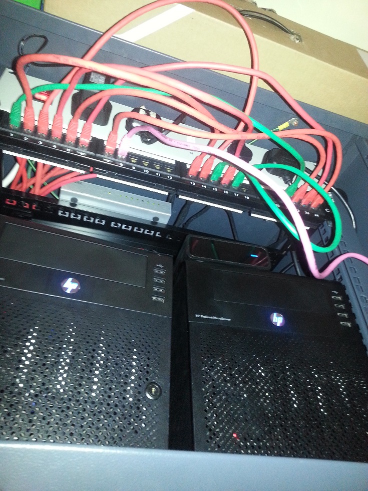
I've got a 12u Network comms rack (55cm overall depth) under my stairs that currently has the 2x HP servers along with switch, patch panel and other bits:
So I decided to look for a Short depth (~40cm) 3U or 4U case with enough space for the 8 3.5" drives along with the SSD.
There were plenty of options but in the end I decided upon the Logic Case 3U SC-34390 (Manufacturer Info Here). Basic looking thing (I'm sure some would say cheap!) but seems to be up to the task. Claims space for up to (important - see pics below!) 8 x 3.5" drives and 3 x 5.25" drives (optional 3 x 5.25" bay to 5 x 3.5" and 120mm fan mount available here) so a potential 13 x 3.5" drives!
Mine came and had 2 x 80mm 4 pin Molex fans at the front and 2 x 60mm 4 pin Molex fans in the rear.
(Just as a point of note, the pics from now on are from various date/time stages so not true chronological pictorial by any means!)
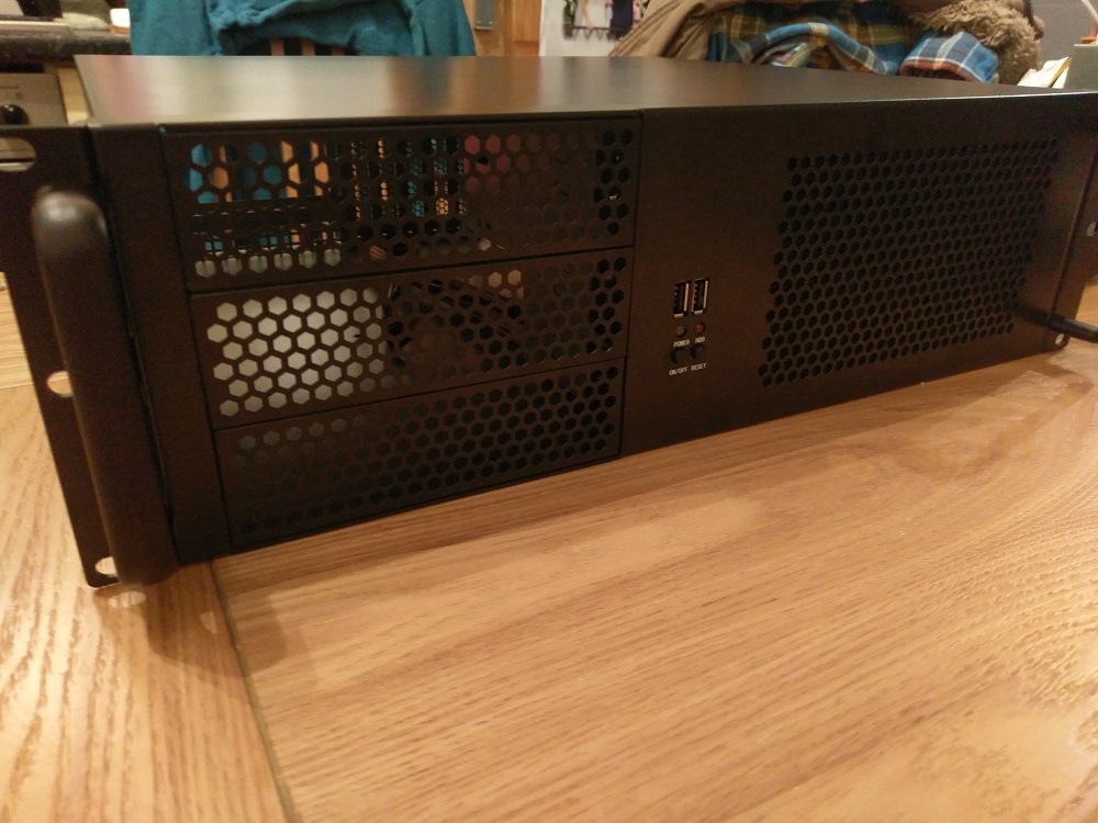


So, first point, the two hard drive cages at the front are very deep:

They're screwed to the bottom of the case so you'll need a Philips screw driver with a long shaft (giggidy)
Second point (and something I should have checked before ordering the case), there's no way you'll ever be able to use all 8 of the front 3.5" bays with a full size MATX motherboard. I've not actually got to the point of fitting the drives yet but there's a potential chance the second bay up may be unusable too (hope this isn't the case! ) A short width MATX/Mini ITX board will be fine I'm sure but no chance with this Dell T20 motherboard:

Third point, given the motherboard / psu slot placement, the 4 pin 12V connector is way too short to reach back over to the other side of the board:

One 45CM extension cable routed under the motherboard later and we're good:


Fourth point, the Power button cable, Front IO panel and system fan header connectors are all Dell proprietary. This is the thing that's proven to be the biggest head ache so far!
With a quick bit of tinkering with a screw driver, I found the two far right pins to be power switch (black and yellow on the original connector)

It's alive!
But wait, it's not that easy

All three of the afore mentioned connectors have detectors so if they're not connected or failed, you get this lovely error which you have to hit F1 on every boot to get past. Given this is going under the stairs and I want to be able to deal with remotely, this isn't good
The obvious answer here for the Power and Front IO at least, was to simply take the existing cable and fit them into the case but that would mean more modding so decided to look into alternatives first and use the retro fitting as a last resort.
Fan First
As utter luck would have it we were chucking out some old Dell Optiplex SX280 at work which I'd randomly stripped a month or two ago. The hoarder in me couldn't bring myself to bin the 60MMx38MM fans that were in the things so I held on to them. Wonderfully, they're an exact fit with the same header connector as the old 92MM fan that came with the server originally:

I replaced one of the rear 60MM fans with this one and thankfully it works and the error is now gone!

One down, two to go!
Power Cable
Now for the more interesting bit - The headers on the motherboard are smaller than your standard motherboard connectors (from Googling I believe they're what's known as 1.27mm Pitch IDC connectors but I'll stand to be corrected). I'd already worked out the power switch pins so from the fact there are 5 in total with 3 left and the LED was incorporated into the switch, it made sense that two of the pins are for the Power LED, 1 must be the detect pin.
After some trial and error I managed to work out the pin outs for the functions and suppress the error message by shorting the detect pin into the LED.
I was then stuck with how to create a good connection between the socket on the motherboard and the standard case cables. I tried a few different things, the main one being trying to find a converter cable on the bay (I didn't manage to find one so either my Googlefu is weak or I was searching for entirely the wrong thing - for everyone else's sake I hope a simple converter cable exists!)
I then stumbled upon an old 40 Pin to 44 Pin 3.5" IDE to 2.5" IDE converter in my box of random PC bits, as luck would have it, the 2.5" IDE end is exactly the same size as the motherboard headers and the 3.5" end is the same pitch as a standard motherboard header. Too long obviously, but at least a glimmer of hope

I then took to it with a pair of pliers and chopped one end down to a 3 x 2 block. Made sure I sanded the smaller end down to make sure it was reasonably square. I also superglued the opposite end to make sure the wires didn't come away from the connector.
To save having to connect the detect wire at the top end, I stripped back the two relevant wires and gave them a quick blob of solder and wrapped in electrical tape. I then desoldered some of the pins from another old 2.5" to 3.5" IDE board and stuck them in so the case headers could attach.
Connected and even without the LED, no more Power button error.

(Ignore the Molex connector the other end is a Six pin 3x2 block.)
Only downside to this is that the LED in the original switch is two colour, it flashes orange to indicate any diagnostic errors - with this change there's no indicator on diagnostic problems although for now I'm willing to accept that.
Front IO cable
Slightly more convoluted but same process as above
This time making a 10 x 2 cable and again shorting the detect wires together. On the front IO, the detect is actually two distinct pins.

Testing with Front USB and LED connected:

It's alive!

So at this point I'm happy stuff is connected and the error messages aren't occurring anymore. When I get chance I'm going to be looking at transferring RAM / Drives and Network cards over and seeing how I get on with the actual fitting of stuff into the case.
For any other brave (read - stupid ) folks like me who want to case transplant, the pinout for the motherboard headers is as per below:
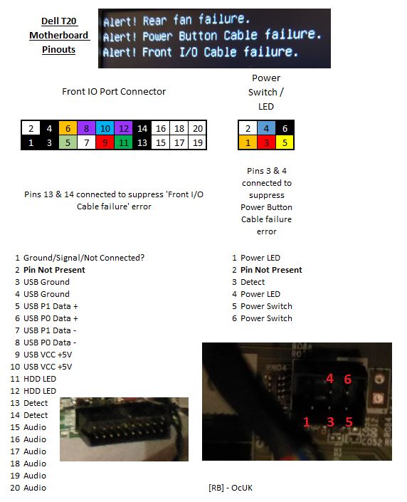
I completely forgot which way round the +/- is wired for the LED so omitted from the Diagram and I've not bothered working out the headphone/mic jacks as I have no intention of ever using them but they should be simple enough to figure out
I hope this helps some folks as it's certainly been annoying me for a week or two

The N54L ESXI host has:
- 8GB RAM
- 256MB SSD
- 4 x 2TB drives
- Intel PCIE NIC
The N36L Nas4Free host has:
- 8GB RAM
- 4 x 3TB drives
- Intel PCIE NIC
So looking at consolidating these two systems, I have an issue with the drives. Adding a RAID/HBA card in is not an issue but the T20 physically only has room for 4 x 3.5" drives by default.
There's a great thread by Schoondoggy over at Homeservershow (Here) detailing how to easily add 2 more 3.5" drives with the addition of a dell drive cage but these are around £25 on the bay and still only get me up to 6 drives.
In the same thread, there's a link to another forum where some chap has deconstructed the case and riveted together multiple Dell drive cages to get up to a total of 8 (Here - pretty nice job if you ask me
 ). This would be perfect but extends beyond the scope of my DIY abilities by some margin!
Given this, I could either look to buy 4 new drives of larger capacity (4/5TB) or look for another case to transplant the system into.
With hindsight, I should probably just have stuck to the buying new drives option but decided to go for the new case option instead.
I've got a 12u Network comms rack (55cm overall depth) under my stairs that currently has the 2x HP servers along with switch, patch panel and other bits:

So I decided to look for a Short depth (~40cm) 3U or 4U case with enough space for the 8 3.5" drives along with the SSD.
There were plenty of options but in the end I decided upon the Logic Case 3U SC-34390 (Manufacturer Info Here). Basic looking thing (I'm sure some would say cheap!) but seems to be up to the task. Claims space for up to (important - see pics below!) 8 x 3.5" drives and 3 x 5.25" drives (optional 3 x 5.25" bay to 5 x 3.5" and 120mm fan mount available here) so a potential 13 x 3.5" drives!
Mine came and had 2 x 80mm 4 pin Molex fans at the front and 2 x 60mm 4 pin Molex fans in the rear.
(Just as a point of note, the pics from now on are from various date/time stages so not true chronological pictorial by any means!)


So, first point, the two hard drive cages at the front are very deep:

They're screwed to the bottom of the case so you'll need a Philips screw driver with a long shaft (giggidy)
Second point (and something I should have checked before ordering the case), there's no way you'll ever be able to use all 8 of the front 3.5" bays with a full size MATX motherboard. I've not actually got to the point of fitting the drives yet but there's a potential chance the second bay up may be unusable too (hope this isn't the case!
 ) A short width MATX/Mini ITX board will be fine I'm sure but no chance with this Dell T20 motherboard:
Third point, given the motherboard / psu slot placement, the 4 pin 12V connector is way too short to reach back over to the other side of the board:

One 45CM extension cable routed under the motherboard later and we're good:


Fourth point, the Power button cable, Front IO panel and system fan header connectors are all Dell proprietary. This is the thing that's proven to be the biggest head ache so far!
With a quick bit of tinkering with a screw driver, I found the two far right pins to be power switch (black and yellow on the original connector)

It's alive!

But wait, it's not that easy


All three of the afore mentioned connectors have detectors so if they're not connected or failed, you get this lovely error which you have to hit F1 on every boot to get past. Given this is going under the stairs and I want to be able to deal with remotely, this isn't good

The obvious answer here for the Power and Front IO at least, was to simply take the existing cable and fit them into the case but that would mean more modding so decided to look into alternatives first and use the retro fitting as a last resort.
Fan First
As utter luck would have it we were chucking out some old Dell Optiplex SX280 at work which I'd randomly stripped a month or two ago. The hoarder in me couldn't bring myself to bin the 60MMx38MM fans that were in the things so I held on to them. Wonderfully, they're an exact fit with the same header connector as the old 92MM fan that came with the server originally:

I replaced one of the rear 60MM fans with this one and thankfully it works and the error is now gone!

One down, two to go!
Power Cable
Now for the more interesting bit - The headers on the motherboard are smaller than your standard motherboard connectors (from Googling I believe they're what's known as 1.27mm Pitch IDC connectors but I'll stand to be corrected). I'd already worked out the power switch pins so from the fact there are 5 in total with 3 left and the LED was incorporated into the switch, it made sense that two of the pins are for the Power LED, 1 must be the detect pin.
After some trial and error I managed to work out the pin outs for the functions and suppress the error message by shorting the detect pin into the LED.
I was then stuck with how to create a good connection between the socket on the motherboard and the standard case cables. I tried a few different things, the main one being trying to find a converter cable on the bay (I didn't manage to find one so either my Googlefu is weak or I was searching for entirely the wrong thing - for everyone else's sake I hope a simple converter cable exists!)
I then stumbled upon an old 40 Pin to 44 Pin 3.5" IDE to 2.5" IDE converter in my box of random PC bits, as luck would have it, the 2.5" IDE end is exactly the same size as the motherboard headers and the 3.5" end is the same pitch as a standard motherboard header. Too long obviously, but at least a glimmer of hope


I then took to it with a pair of pliers and chopped one end down to a 3 x 2 block. Made sure I sanded the smaller end down to make sure it was reasonably square. I also superglued the opposite end to make sure the wires didn't come away from the connector.
To save having to connect the detect wire at the top end, I stripped back the two relevant wires and gave them a quick blob of solder and wrapped in electrical tape. I then desoldered some of the pins from another old 2.5" to 3.5" IDE board and stuck them in so the case headers could attach.
Connected and even without the LED, no more Power button error.

(Ignore the Molex connector the other end is a Six pin 3x2 block.)
Only downside to this is that the LED in the original switch is two colour, it flashes orange to indicate any diagnostic errors - with this change there's no indicator on diagnostic problems although for now I'm willing to accept that.
Front IO cable
Slightly more convoluted but same process as above

This time making a 10 x 2 cable and again shorting the detect wires together. On the front IO, the detect is actually two distinct pins.

Testing with Front USB and LED connected:

It's alive!

So at this point I'm happy stuff is connected and the error messages aren't occurring anymore. When I get chance I'm going to be looking at transferring RAM / Drives and Network cards over and seeing how I get on with the actual fitting of stuff into the case.
For any other brave (read - stupid
 ) folks like me who want to case transplant, the pinout for the motherboard headers is as per below:
I completely forgot which way round the +/- is wired for the LED so omitted from the Diagram and I've not bothered working out the headphone/mic jacks as I have no intention of ever using them but they should be simple enough to figure out

I hope this helps some folks as it's certainly been annoying me for a week or two

Last edited:
Wow that is all I can say, I really like that case and eventually will try and do the same.
What is the case?
Can I see a picture of the whole finished server.
I bought one recently and my son setup, he did mention that the HD power leads are also a little different.
What SATA card did you use and how did you connect the extra drives?
Are you also using the normal NIC or did you add the Intel PCI NIC? Does it make any difference?
What are the final specs, RAM etc
Thanks
Associate
Wow that is all I can say, I really like that case and eventually will try and do the same.
What is the case?
Can I see a picture of the whole finished server.
I bought one recently and my son setup, he did mention that the HD power leads are also a little different.
What SATA card did you use and how did you connect the extra drives?
Are you also using the normal NIC or did you add the Intel PCI NIC? Does it make any difference?
What are the final specs, RAM etc
Thanks
The server is still a work in progress at the moment but I'll add pics when I'm done

Case is this one as per my previous post:
Logic Case 3U SC-34390 (Manufacturer Info here)
I've got an IBM M1015 in there purchased from the Members Market. This will give 8 drives in addition to the 4 on-board SATA ports. There are only 4 SATA power connectors that are provided from the proprietary 8 pin connector that comes out of the motherboard.
I've got 2 x 1 into 4 SATA power splitters for the 8 Mechanical drives, I'll use 1 of the standard for the SSD and 1 SATA to Molex to power the fans.
I've got two single port Intel NICS and 1 Dual port NIC. I've not really decided how many I'll need yet and as I only have the low profile bracket for the Dual port I may end up with the two singles.
Subject to it all fitting in
 - the final spec should be:
- Xeon E3-1225V3 3.2 GHz
- 16 GB RAM
- 256GB SSD
- 20 TB of Mechanical Drive
- IBM M1015
- 2 x Intel Gb NIC
nothing special really

Associate
Excellent write up, I'm thinking of doing the same but contemplating if I should go for a case with slot loading drives http://www.logic-case.com/products/rackmount-chassis/4u/4u-short-storage-chassis-w-8x-35-sata-hot-swap-bays---eatx-motherboard-support-sc-43400-8hs/
Associate
Excellent write up, I'm thinking of doing the same but contemplating if I should go for a case with slot loading drives http://www.logic-case.com/products/rackmount-chassis/4u/4u-short-storage-chassis-w-8x-35-sata-hot-swap-bays---eatx-motherboard-support-sc-43400-8hs/
Given the layout of the one I have, that 4U would definitely be a better option I'm sure.
/edit
and the layout of the PSU/Mobo means you'll pretty much not need the 12v extender too.
Associate
- Joined
- 20 Apr 2009
- Posts
- 1,269
Wow, that's a fantastic write up. Nice work
fantastic writeup cheers 
question for everyone please - have Windows 10 Pro installed - Intel TurboBoost - appears not to be working ? I have a 1225v3 Xeon - max multiplier I can see in CPU-Z is 32x (say 36 is max - but it never goes above 32x)
I've tried stressing with Prime95 - one core, 4 cores, never above 3.2 gig
it is enabled in the bios
any ideas please ?
Associate
So after the previous post I've not had much time to get round to actually doing the transplant of stuff.
The main problem I found was that with all of the supplied fans plugged in, it was just too loud - even when out of the way under the stairs. Appreciating that this is designed to be sat in a rack in a machine room I can't grumble too much about it as the fans do shift quite a bit of air.
With this in mind, I looked for a solution to replace the existing fans and potentially getting the PWM feed from the Dell fan header out to the other fans.
In the end, I bought 2 x 80mm fans - these to be specific
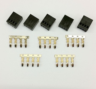
I was struggling to find cheap 60mm fans that had PWM so I decided I would keep the Dell ones that I mentioned previously and removed the Dell 5 pin connectors and attached standard 4 pin headers:
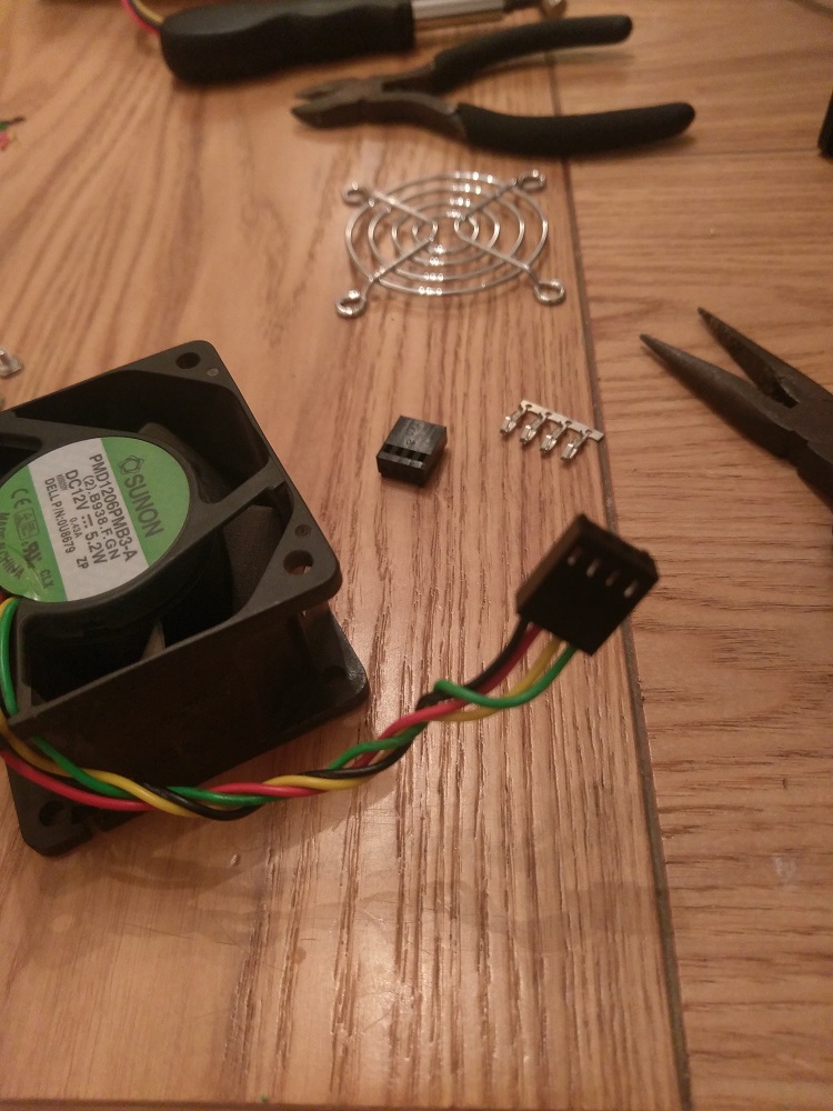
The 80mm fans came with PWM sharing cables attached which effectively just passes the power and PWM signal through to any fans connected:

As these weren't needed, I popped the pins out of the headers and removed them just leaving the standard 4 pin connector.
The fan holder at the front of the case was removed and I set about replacing them:

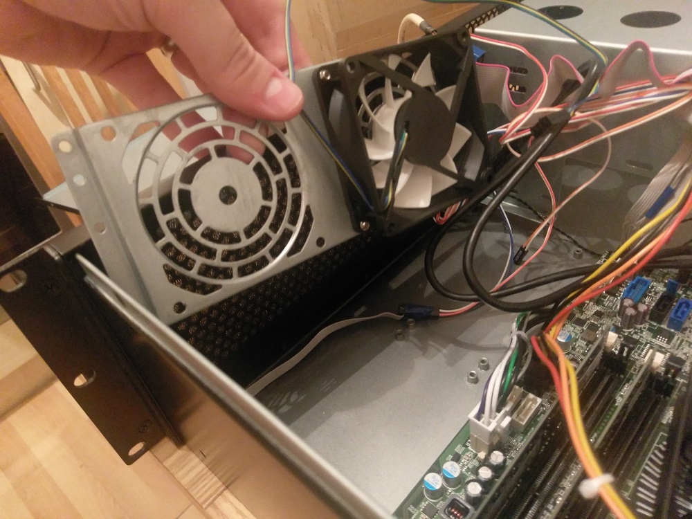
In order to get power and PWM signal around the case I ended up buying an Evercool EC-DF001 splitter.
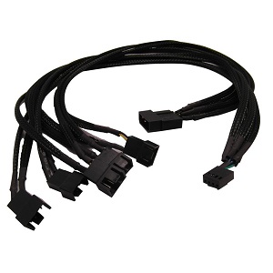
This is just stuffed under the power supply and I've fed all of the fan cables to it. This gives 5 fan connectors, powered by a molex connector and has a single header to connect to the motherboard.
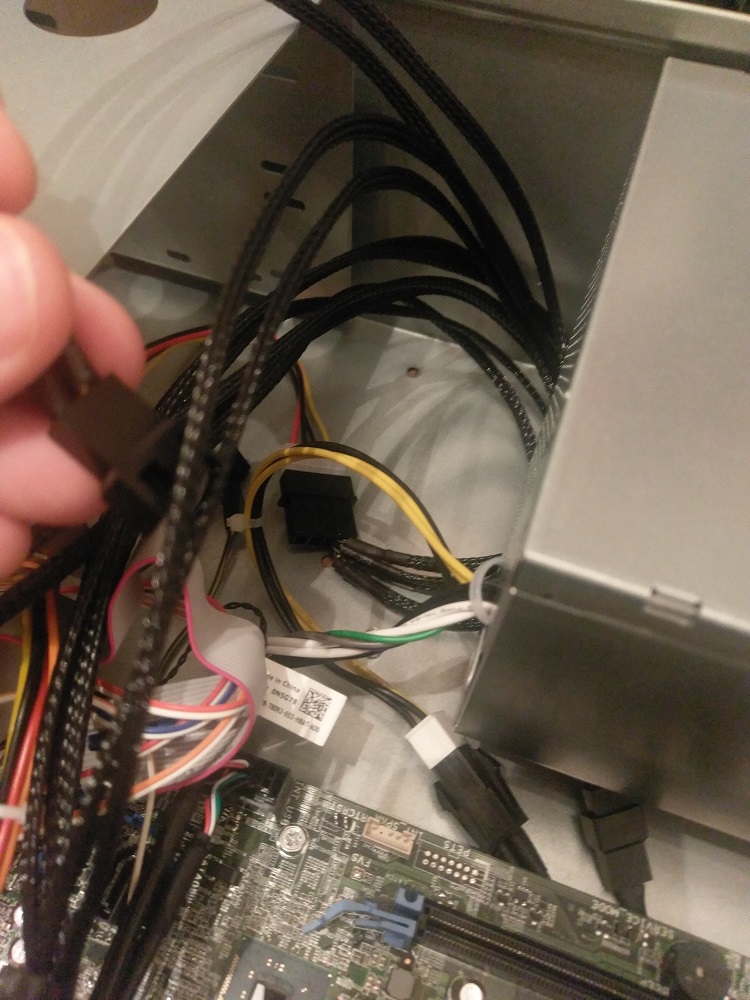
In the same picture above, you can see the end of a standard PWM extension cable:
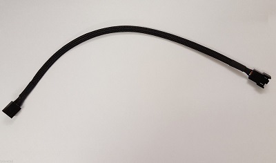
This has been fed under the motherboard and sits just at the side of the Dell fan header:
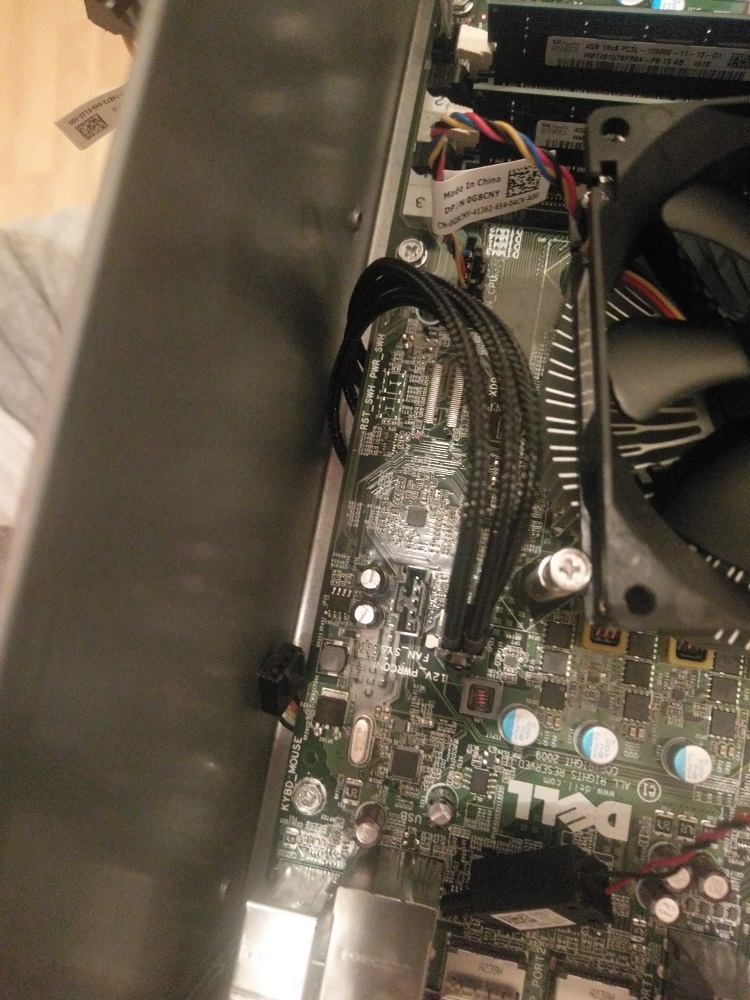
The final piece was connecting this 4 pin header to the 5 pin dell header.
I took one of the PWM passthrough connectors I'd removed earlier, along with one of the dell 5pin headers from the 60mm fans. i checked the pinouts were correct and then soldered the two wires together to create a little adaptor (I found these ones on the Bay if you cba messing here )
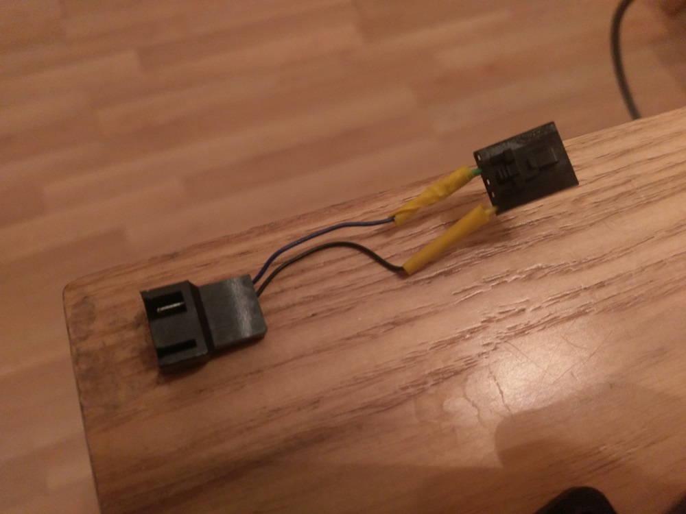
Wrapped it in a little tape and plugged in (not pretty I appreciate!)
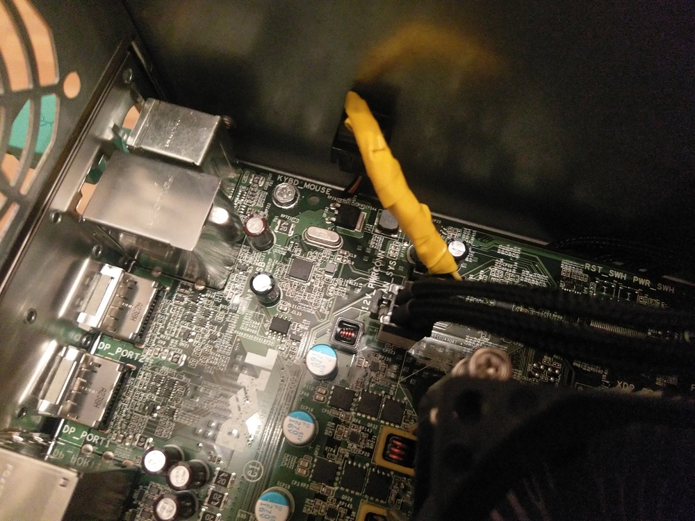
Success! No error message on boot
Pic of all the fans connected and running - hard drive cages removed (this was taken before some slight tidying of all the wires on display)
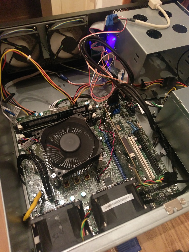
I then added the 1TB Drive that originally came with the T20 to the 3rd slot to see if it would fit - it's tight:
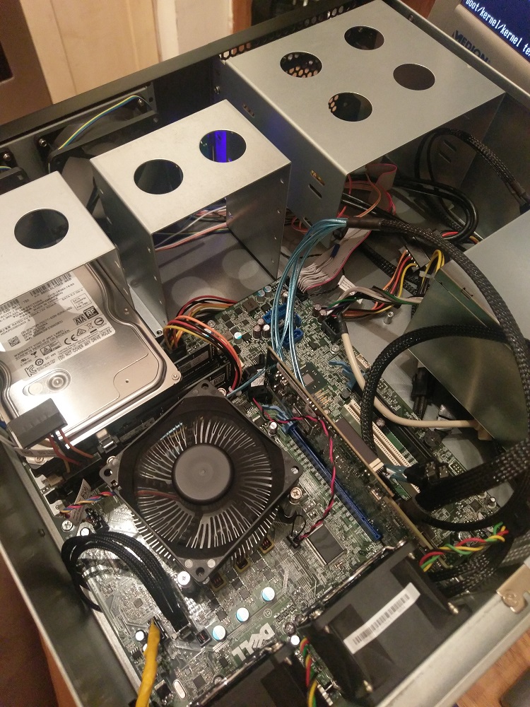
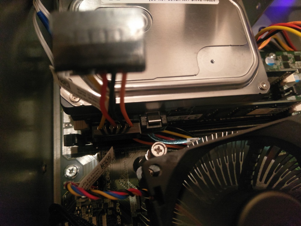
mm between the top of the RAM and the bottom of the hard drive!
I think I'm just going to attach some kind of plastic sheeting to the bottom of the hard drive as a precaution for now and see how I get on.
Another thing I spotted (and is evident on the picture 3 above - USB 3 internal cable attached to top right of motherboard) is that with a conventional USB3 cable connected to the header you'll not be able to use the hard drive being installed in the 3rd slot on the right cage. I found some right angled connectors from a bit of Googling but for now i think I'm just not going to bother and stick with the standard USB2
At some point I'll look to do the actual meat and bones of the transplant when time allows!
The main problem I found was that with all of the supplied fans plugged in, it was just too loud - even when out of the way under the stairs. Appreciating that this is designed to be sat in a rack in a machine room I can't grumble too much about it as the fans do shift quite a bit of air.
With this in mind, I looked for a solution to replace the existing fans and potentially getting the PWM feed from the Dell fan header out to the other fans.
In the end, I bought 2 x 80mm fans - these to be specific
I was struggling to find cheap 60mm fans that had PWM so I decided I would keep the Dell ones that I mentioned previously and removed the Dell 5 pin connectors and attached standard 4 pin headers:


The 80mm fans came with PWM sharing cables attached which effectively just passes the power and PWM signal through to any fans connected:

As these weren't needed, I popped the pins out of the headers and removed them just leaving the standard 4 pin connector.
The fan holder at the front of the case was removed and I set about replacing them:


In order to get power and PWM signal around the case I ended up buying an Evercool EC-DF001 splitter.

This is just stuffed under the power supply and I've fed all of the fan cables to it. This gives 5 fan connectors, powered by a molex connector and has a single header to connect to the motherboard.

In the same picture above, you can see the end of a standard PWM extension cable:

This has been fed under the motherboard and sits just at the side of the Dell fan header:

The final piece was connecting this 4 pin header to the 5 pin dell header.
I took one of the PWM passthrough connectors I'd removed earlier, along with one of the dell 5pin headers from the 60mm fans. i checked the pinouts were correct and then soldered the two wires together to create a little adaptor (I found these ones on the Bay if you cba messing here )

Wrapped it in a little tape and plugged in (not pretty I appreciate!)

Success! No error message on boot

Pic of all the fans connected and running - hard drive cages removed (this was taken before some slight tidying of all the wires on display)

I then added the 1TB Drive that originally came with the T20 to the 3rd slot to see if it would fit - it's tight:


mm between the top of the RAM and the bottom of the hard drive!

I think I'm just going to attach some kind of plastic sheeting to the bottom of the hard drive as a precaution for now and see how I get on.
Another thing I spotted (and is evident on the picture 3 above - USB 3 internal cable attached to top right of motherboard) is that with a conventional USB3 cable connected to the header you'll not be able to use the hard drive being installed in the 3rd slot on the right cage. I found some right angled connectors from a bit of Googling but for now i think I'm just not going to bother and stick with the standard USB2
At some point I'll look to do the actual meat and bones of the transplant when time allows!
I'm seriously considering grabbing one of these or similar for a pfSense install to replace our trusty little APU2C4. A quad core Xeon at 3.2GHz will eat OpenVPN alive and give wire speed (300Mbps) over our Virgin Media connection. The supplied RAM is plenty, and I have a spare 30GB SSD I can throw in there, but can anyone tell me about the NIC? I presume it's a single port affair, so I'd have to put in a dual port PCIe Intel card? I have a few of those knocking around.
I actually found some excellent ex-datacentre 1u HP boxes on eBay for £80 (dual Xeon with 16GB RAM), but I just can't have 1u noise in our living room where the networking stuff has to live. Is the T20 going to be my best bang for buck alternative?
ETA: Actually, ironically, if it would take my R9 380 and it takes regular DDR3 RAM, it would actually be a more powerful system than my current desktop if I swapped the components into it and then recycled my current desktop as the firewall.
I actually found some excellent ex-datacentre 1u HP boxes on eBay for £80 (dual Xeon with 16GB RAM), but I just can't have 1u noise in our living room where the networking stuff has to live.
 Is the T20 going to be my best bang for buck alternative?
ETA: Actually, ironically, if it would take my R9 380 and it takes regular DDR3 RAM, it would actually be a more powerful system than my current desktop if I swapped the components into it and then recycled my current desktop as the firewall.

Last edited:

