Reservoir concept. With picture :)

Soldato
Joined
22 Dec 2008
Posts
10,369
Location
England
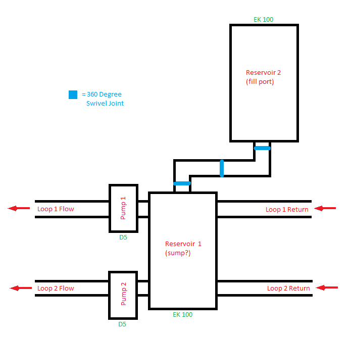
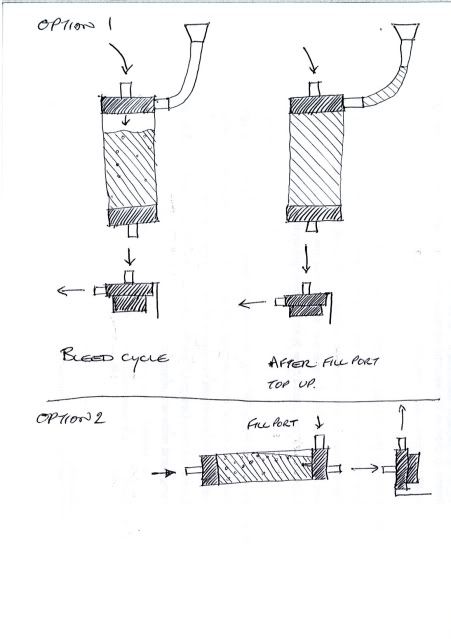
Hey guys. A reservoir is lovely, because it makes filling and bleeding really quick and easy. Well, relatively. A T line is better for flow rate as the water is not being accelerated and decelerated in the reservoir. So here for your viewing pleasure, I propose the following solution.

ibcbiq.jpg


Ideallised of course. In case it isn't immediately obvious, you open the valve while filling and bleeding the system, at which point it behaves like a reservoir normally does. Once bled, you close the valve, and the system proceeds to work just like a T line. It would be wise to have the valve physically above the T, but coming from the middle section. Not quite as shown here, this made for a nicer picture. Dimensions are by eye for the ddc and valve, 11mm tubing, ignored barbs and drew a purely imaginary radiator.

Criticism of concept welcome. Criticism of solid edge + paint also welcome :D
 
would the reseviour not have to be below the rest of the system to bleed it, and if you do put it at the bottom how do you then fill the system from the bottom up?
 
Bleeding is removing the air, which tends to accumulate at the top. It accumulates in T lines without any issue, so while the above T might need to be rotated 90 degrees the reservoir definitely doesn't want to be at the bottom.

This is seperate from draining the system, though if you were so inclined you could turn the entire thing upside down and drain that way. I'm using a T line at the bottom to drain at the moment.
 
Jon,

I have used a t junction and a ball valve so that it can drain etc but the problem I have encountered is if I open the valve it only drips out slowly. So I undone the reservoir and then the reservoir filled up to the point the liquid poured out of where you fill it and not from the valve I added for this reason??
 
I don't quite follow I'm afraid. Is the reservoir near the top of your case, or below the drain valve? The valve needs to be as far down as possible. You open it, and it drips. You then open the reservoir so air can get in, and a load will come out. But not all. You then run the pump until the reservoir is mostly empty.

Now most water is out. cap the reservoir, close the valve, and tilt the case around, aiming to get more liquid in the reservoir. You then start from the beginning. It's almost impossible to get all the water out, once close I tend to blow into the reservoir as if blowing up a ballon.

Does this help?
 
What do you think of this Jon?

pumpandres.png


This is my current setup. Res 1 acts as the source for the pumps, Res 2 acts as the fill port.

I can swing Res 2 out of the case and rotate it all directions. Handy for draining as It allows me to tilt/rotate the case and squeeze every last drop out. This is just something I'm trying out, for now.
 
The only problems I can see with this are the fact that you will have to same problem as any standard T line, in that it will take ages to get every last tiny bubble out of every nook and cranny in the loop where little bubbles collect, only in this case you will have to be dead sure every last one is gone before you close the valve, otherwise they will just collect in the rad, or anywhere else it can become trapped, depends on how fastidious you are about getting that last scrap of air out of your loop. I guess it would be worse if there was nowhere it could collect and it ended up continously going round the loop though. The other problem which may be more significant is what would happen as water leaches out of the loop via the tubes over time. What would this do to the static pressure in the loop? I know water leaches out in mine because the level in my EK150 multioption rez must have dropped about 10mm since I set the thing up 6 months ago. Water leaving a sealed air tight system must reduce the static pressure in the loop which is why the air pocket in the rez "expands", unless air leaches the opposite way which I don't think it does. What would happen in a system with no expandable air pocket? However, this could quite easily be overcome in your set up by periodically opening the valve to kind of let some water back in to the loop if you get me, assuming you are not planning on removing the res from your case completely once you've finished bleeding for anti-clutter purposes.

Edit: I guess you will be okay on the first point since you say you will orient the valve so you will effectively have a stubby T line for any remaining air to collect, i.e. the stubby bit would have to be vertical, same as a normal T line. Now that I think of it in those terms, I can't actually see the advantage of using the full size rez, as when you are first bleeding the system it behaves exactly as T line alone would, you wouldn't get the advantages of a rez when filling this system, and once you close the valve the rez might as well not be there. If a pocket of air collects in the void below the now closed valve then that will expand and contract as a normal T line would. In effect you are back to having a simple T line? Infact, in your pic you could replace the rez with a picture of a funnel and that would look exactly like anyone filling a T line system, minus the valve?

If you wanted to combine the advantages of a rez when filling, and a T line when in operation, you would have to make a bypass so that water can flow in and out of the rez, rather than just out as in your pic. You would need two T pieces and 3 valves for this.

It would be system - T1 - valve1 - T2- pump -system, and the res section would be T1 - valve2 - rez -Valve3 - T2

When filling/bleeding, shut valv1 and open valves 2 and 3. When finished bleeding open valve 1 and shut vales 2/3. The question is, is the pressure drop due to the addititional two T's and a valve less than the pressure drop through a res as it is normally used. One thing is for sure it will look messy.
 
Last edited:
@Too many pcs I think you want the two flow paths crossing to encourage the water to mix together before proceeding back through a pump, at present your loops are almost thermally isolated. The second reservoir is pretty much the same concept as here but taken to extremes, I'm not sure I would bother but can see it making filling and draining a lot easier.

@Bubo thank you. That's not enough for me to give up on the design, but it is enough for me to refine it. I'll knock up a new picture in a moment.

The advantage in filling is having half a litre or so of water draining into the loop, I'm concerned that filling from an 8mm T line means it has to be long, and it will take a very long time since my loop holds about 1.5 litres already and that's only going up from here. I'll see what you make of rev 2 :)

mbjxjr.jpg


Indeed, it still has the limitations of a T line. However, it should be about as good as a T line can get, since the only place air can collect is around the ball of the valve, and this will tend to come loose with tapping. There is indeed no space for air to accumulate and be removed, or at least barely any. So this is more about achieving a closed loop without needing to submerge one section to fill it, although it can be viewed as a very short T line.

It is very similar to filling a short T line with a funnel. Borderline identical. Except no chance of leaks, and it is practical to run with the reservoir attached for the first fortnight or so if that's how long it takes for the loop to bleed.

I have a revision 3 in the works already, which will perhaps just be completely excessive. Turns out it's quite hard to draw, and would need me to machine bits of copper myself, for negligible gain, maybe scrap rev 3


Perhaps it would help to mention why this seems a good idea for me. I have a foolishly arranged loop which takes a long time to bleed, i want to change to a T line for the marginal performance increase but don't think it would be practical for getting the air out. So the above is a T line which should catch air nearly as effectively as a reservoir, or at least better than a T line normally does because I won't need to continually refill it.
 
Last edited:
Bleeding time ( :D ) is really not worth worrying about. If the water is busy flowing then the cooling is still good enough to power up and so what if it takes 24 hours to bleed fully? How often does it need to be done?
 
The XSPC reservoir top actualy gives the best flow of any DDC top according to Martins Liquid Labs, so unless you are extremely tight on space, I would go with that and just live with the gurgles for 24 hours while it bleeds itself.
 
Been thinking of something simular untill the typhoon 3 comes back in stock.

But it's more like a t-line attached to an unside down res, instead of the JonJ's res on a t-line.
(Danger Den do a res/fillport btw - which is just a mini version of what your showing)

fillportres.jpg


Option 1.
Would make better use of space in my case but I either need to mod the EK so that in/outlet chambers
are joined (not ideal for resale) or use a T or Y to link them both to the fill port.

Option 2.
No before and after cycle as inlet and out let below bubble.
Res tilted for first few hours to assist bleed but in/out chambers will help stop bubbles recurlating.

Never really under stood why anyone would want a tall (heavy) piller of water pushing down on the Res in & out lets.
Pushing on the outlet yes - as it makes up for the flow loss due to the bubble.
But an inlet at the bottom of a res is only usefull for bleading and kills flow - unless I'm missing something (which is quite likely :D)
 
Last edited:
Personally i think it would be better to use a Y connector than a T if possible.
As a T would cause flow rates to drop a touch due to the T bringing in fluid from the res that is completely still in the plane of flow which would then have to be accelerated. Also the hydrostatic pressure may send a small amount of the flow up towards the res, it would obviously come back down but then it's lost some of it's speed.

Having a Y would mean that when the new fluid joins the flow it is already moving in the right direction also you should have less of a back flow problem as the speed of the fluid would counter most of the force from the pressure.


You may want to add double valves too.
With a single valve all you can do is shut off the connection but then if you try to remove the res when it isn't completely empty you'll end up with all the excess leaking out inside your PC.
Have a double valve means that only the tiny amount between the valves can leak out if you detach the res when it's still partially full.
 
Bleeding becomes difficult when the volume of air in the system significantly exceeds the capacity of the T line, hence this :)

The xspc res top does well, but it is inferior to a bled, closed loop. There's simply no way it could be otherwise. I'm not sure I can estimate the difference. I'm using the xspc res top at the moment for the usual reasons, but I don't like or trust it. If anywhere in my loop is going to leak, it's going to be there.

Aesthetics are not my strong point, I could render it to look remotely like brass if you prefer...

A Y in that direction would also mean it would never bleed I fear. Double valves is a good point, though by that stage quick disconnect may be the way forward.

-----------------------------------------------------------------------------------------------------------------------

Interesting sketch shadow. It's taking me a while to spot the subtleties

I'm impressed, with both options. Each involve a pressure drop across the reservoir, but that's the same with any res. Option 1 makes a lot of sense by itself, but also happens to be exactly the same as the xspc reservoir. I'm running a fill line up from the fillport, looking at option 1 in place and running in my computer.

The second is an interesting use of the ek res. The bubble would be out of the way of the flow, however this is normally the case in reservoirs. I thought they all did water in at the top and out at the base, the other way round makes no intuitive sense at all. I like the aesthetics of the inline res, but am not sure it offers any improvement over the alternatives. Perhaps I'm missing something?
 
Last edited:
Option one is indeed like the DDC + Res top.
Except It's with a D5 (that doesn't have that option, other that the Typhoon 3)

It's possable to link a EK res directly to a EK X-top, but would be pointless geting a X-top for 2 weeks.
So I'm using what I have ;)

After the bleed is complete - a variable pump really helps here - in both options the T-line is used to remove
the bubble from the res. With the fill port sealed there should be very little pressure drop across the Res
as it becomes a sealed loop. Remove the bubble - remove the presure drop - thats my theory anyway.

Most people have the in and outlet at the bottom of an EK res.
Wasn't surgesting inlet at bottom outlet at top
 
Last edited:
Been thinking of something simular untill the typhoon 3 comes back in stock.

But it's more like a t-line attached to an unside down res, instead of the JonJ's res on a t-line.
(Danger Den do a res/fillport btw - which is just a mini version of what your showing)

fillportres.jpg


Option 1.
Would make better use of space in my case but I either need to mod the EK so that in/outlet chambers
are joined (not ideal for resale) or use a T or Y to link them both to the fill port.

Option 2.
No before and after cycle as inlet and out let below bubble.
Res tilted for first few hours to assist bleed but in/out chambers will help stop bubbles recurlating.

Never really under stood why anyone would want a tall (heavy) piller of water pushing down on the Res in & out lets.
Pushing on the outlet yes - as it makes up for the flow loss due to the bubble.
But an inlet at the bottom of a res is only usefull for bleading and kills flow - unless I'm missing something (which is quite likely :D)

Thats pretty much how I did mine:

insiden.jpg


I use the bottom part of an EK multi-option 100 res and attach it to the top of my Ek-140 X-res.

Block one side of the anti cyclone chamber to be the return of the water cooling system.

The other side is for bubble collection and has a 3/8" barb to connect to a short piece of hose for filling.

When its filled and the system is air free (make sure the system is running for this one) detach hose and plug the barb for a completely silent air free system.
 
That a really tidy res installation Deadman, one of the best I've seen.
Again it's with a DDC but the D5 X-top would acheive something very simular.
The side inlet / top fill line is a good idea - do you find small bubble getting traped by the inlet/anti cyclone chamber?

I do like those 45 degrees fittings - trying to avoid them if possable now I have a full size case.
 
Last edited:
I liked the idea of the typhoon 3 but it has a few issues, the glue they use does not like Fesser products!

**Typhoon III Reservoir System - PEC has a 3-year limited warranty. Use of cooling fluids that contain Ethylene Glycol (Feser One) or any other harsh chemicals void the warranty for this product.
 
That a really tidy res installation Deadman, one of the best I've seen.
Again it's with a DDC but the D5 X-top would acheive something very simular.
The side inlet / top fill line is a good idea - do you find small bubble getting traped by the inlet/anti cyclone chamber?

I do like those 45 degrees fittings - trying to avoid them if possable now I have a full size case.

Thanks :) it works really well.

There are no small bubbles in my system :) but when filling the system yes the anticyclone plate gathers them all up in the bleed valve / barb side ready for fill ups.

The 45 degree fittings are Fesser and are highly recommended.

You should be able to use the EK D5 attachment onto the bottom of an X-res.. i think!
 
Back
Top Bottom