You are using an out of date browser. It may not display this or other websites correctly.
You should upgrade or use an alternative browser.
You should upgrade or use an alternative browser.
Akasa PWM Fan splitters not working?
- Thread starter Snookums
- Start date
More options
Thread starter's postsThe Akasa splitter is a very poor design with multiple wires stuffed into a small connector cavity so what Doyll says could very well be true. It would have been better (but would have cost more to make) they'd used an inline splice or two to join the wires.
Cables are braided
Might be a different splitter than I've seen then. The one I have (and never used) is just a tangling mess of single insulated cables.
Ah the Flexa one. Still has the very same issue with all PWM wires stuffed into one tiny terminal designed for 22-24 AWG that will take 20AWG at a push. It just shouldn't have 5 individual wires stuffed into a single terminal. No wonder you have issues.
Anyway grab a multimeter and check the Pin 4 connections between the master connector and the other connectors. Then check the power and ground between the Molex and the other connectors.
Last edited:

If memory serves - you need to connect for power (molex or sata - dependent upon which Akasa splitter we are talking ) then you need to connect the connector marked as cpu header (or something like that) to the motherboard cpu fan connector and lastly you connect whichever fans you want to run at the same speed to the other connectors..
Am running 4 x 120 fans with mine without any probs ( so far anyway!) .
Check board that it is playing PWM?
Hope the above helps")
Am running 4 x 120 fans with mine without any probs ( so far anyway!) .
Check board that it is playing PWM?
Hope the above helps
If memory serves - you need to connect for power (molex or sata - dependent upon which Akasa splitter we are talking ) then you need to connect the connector marked as cpu header (or something like that) to the motherboard cpu fan connector and lastly you connect whichever fans you want to run at the same speed to the other connectors..
Am running 4 x 120 fans with mine without any probs ( so far anyway!) .
Check board that it is playing PWM?
Hope the above helps
Only thing I can add is fans run at percentage of PWM duty cycle, not a specified RPM. The PWM signal controls fan speed, and RPM sensor reads RPM signal from fan, but motherboard PWM circuitry does not set the PWM signal percent based on RPM is based on percent of PWM percentage.
I don't know if any of the newer motherboard are different, but even if they do use rpm to set PWM, it is only for the master fan on the PWM splitter. All other fan speeds are based only on PWM signal and how their individual PWM to RPM curse are programed on their respective PCBs.
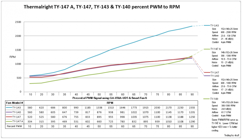
For example here is Thermalright TY-147, TY-147A and TY-143 Both TY-147 & TY-147A are same 1300rpm fans with different PCBs on different PWM to RPM fan curves. TY-143 is 2500rpm and appears to have same PWM to RPM curve as TY-147, but because it is 2500rpm instead of 1300rpm at max speed, the RPM at each PWM signal rate gives TY-143 a much higher speed on same PWM signal rate going to TY-147. TY-147a with different PWM signal rate to RPM program on it's PCB has a different curve than TY-147. Hope that makes sense.