


• Notice regarding image hosts and attachments. See here.

Any Engineers here?

Soldato
Joined
7 Nov 2002
Posts
12,672
Location
Snorbans, UK
Hi guys, just wondering if anyone can help me out with a problem I'm having - I've been trying to work it out for days with no luck.

I've essentially got a piece of box section that had an applied uni-axial load down it (compressive) - however this is via 2 pin joints; this box section is acting as a pushrod for a longer lever:
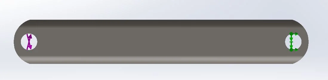
3SR9oeD.webp

(Where Green is the fixture and purple is the load applied..)

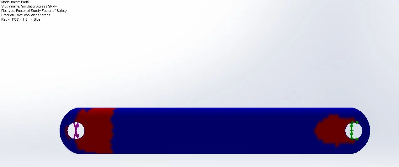
So the load is acting through the holes and compressing this member. I've been trying to use Euler's formula for finding the critical load and allowable stress, but my results are inconsistent with the Stress Analysis I've been doing on Solidworks. Is anyone able to point me in the right direction? As it stands I'm getting massive stress concentrations:
H1Wm2bv.webp


Can anyone help?

Thanks :)
 
Last edited:
Some more information - this is my free body diagram:

U3QuEN6.webp

Where Mg = 29430N
Peak load on Fp (When θ = 6): 281550N

So the load on the member is 281550N, which is essentially transmitted via a pin joint down the member.
 
It's a buckling study; working through Euler's formula for buckling and yield seems to show that that particular member will suffer from buckling above a certain load, so my design states that that load won't be encroached upon, however SW seems to disagree. I'm not sure whether to disregard it and use the maths?
 
Well the load is on a pivoting pin (scissor assembly, so am studying it as a matter of static equilibrium), but the load is always on the same point.
 
You can't even begin to compare a simple analytical formula like "Euler's rule" with a proper finite element analysis. Analytical formulae are only ever, at best, an idealised approximation to the solution of simple problems.

FEA takes into account the geometry of the object, the appropriate traction boundary conditions, and the spatial distribution of loads. If the problem has been set up properly, the question boils down to one of resolution. With a simple convergence analysis ("mesh independence testing") you can quantify the error in your solutions, and then reduce it as low as you like.


...In short - trust the finite element analysis - assuming that you have set it up correctly and used a sufficiently well refined mesh. The plot posted in post #5 looks reasonable to me, but be careful that you are properly representing the effect of any 'pin' that might pass through the holes.


(for what it's worth, numerical methods is what I do for a living. I've written a number of FE / FV / BE codes, though the main focus of my research is meshless methods).

To be honest, I have very limited experience of FEA - this year at Uni is my top-up year - we only did a single module of CAD in the last 2 years - I can model, but I don't really know how to perform FEA properly. Given that this is the case, should I stick to the maths?
 
The free version of FEA in Solid Edge is pretty gash allowing you only to perform analysis on single bodies, so I imagine the same goes for SW. However, a high mesh resolution will help.

Yep, can only do it on single bodies, but Inventor allows you to do it on assemblies. I've set the mesh resolution to "fine", but it seems to have made no difference :/
 
From a quick read over the relevant section, it doesn't seem to cover loading through pin joints or reference stress concentration points?
 
Back
Top Bottom