Associate
- Joined
- 24 Apr 2012
- Posts
- 810
- Location
- Carlow, Ireland
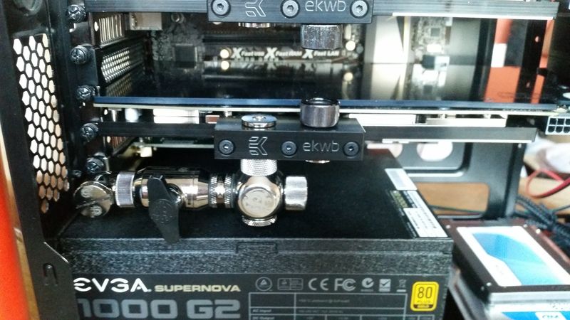
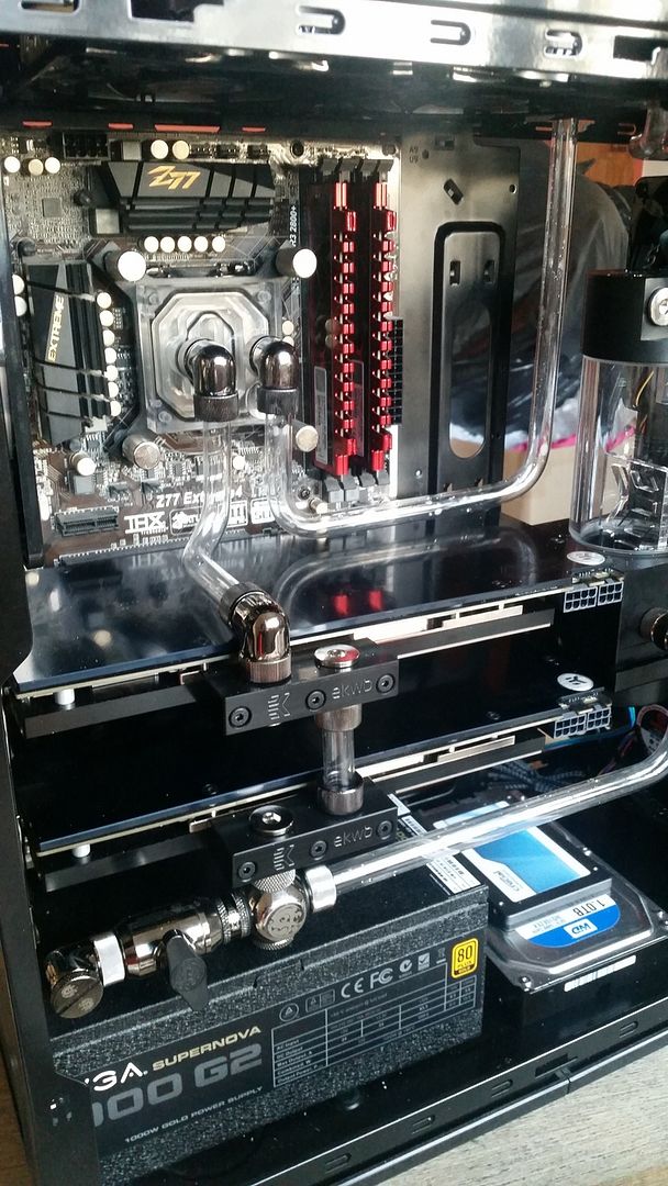
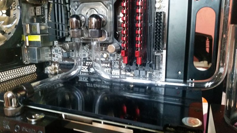
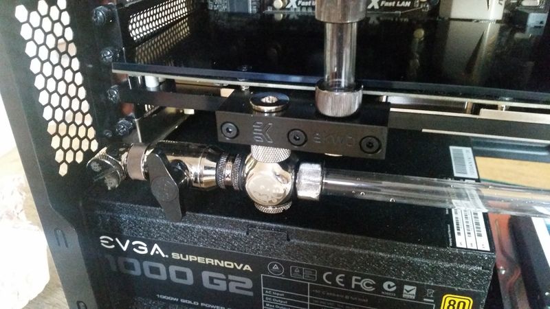
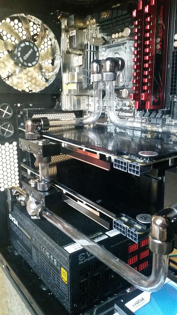
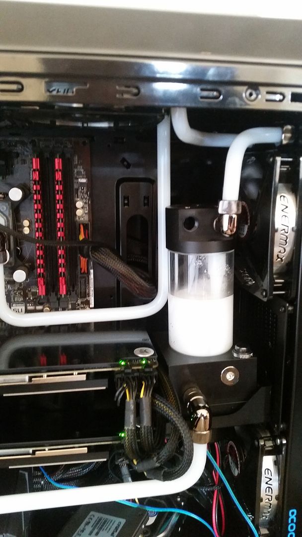
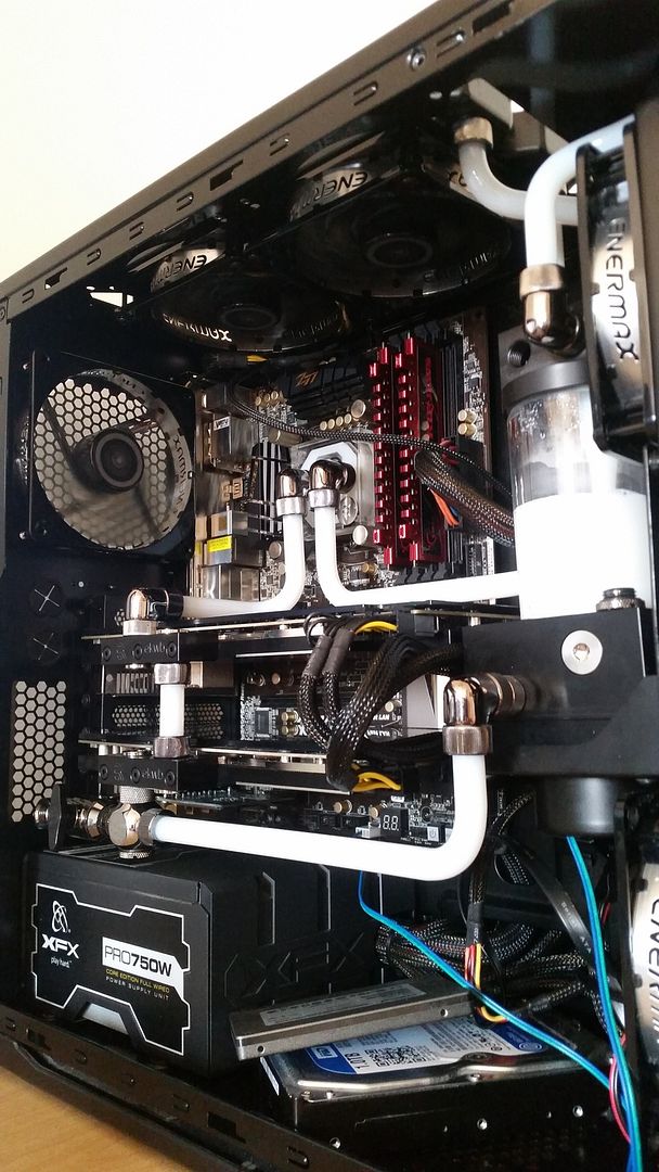
So after 13 months of planning, getting married, having a baby,starting a new job and a move to another town, I have finally broke ground on a case mod and watercooling project I have had in the pipe works for far too long!
The plan is to upgrade my watercool my current system as the 290s are far too hot, I need to set the GPU fans to 100% via Afterburner and turn all 7 case fans up to 12v just to maintain temps of high 80s! Some games reach 94c where my cards start to thermally throttle by up to 20%.
Could I have done this cheaper and easier? Certainly, but where is the fun in that?!
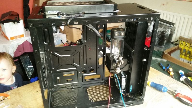
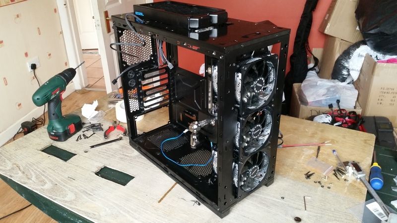
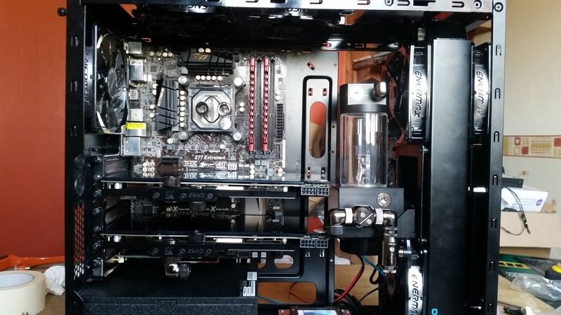
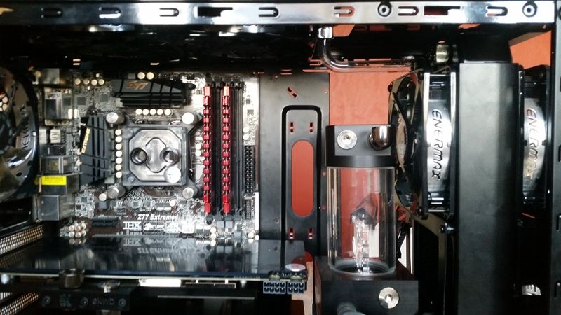
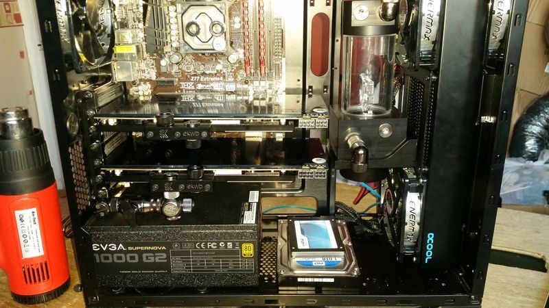
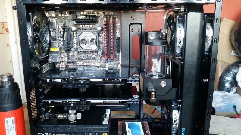
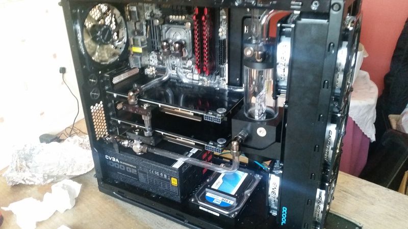
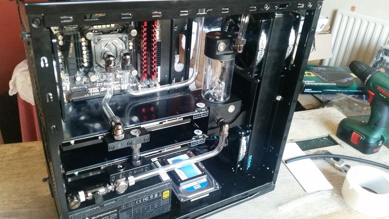
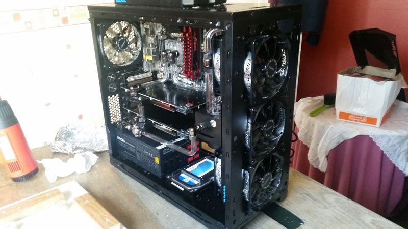
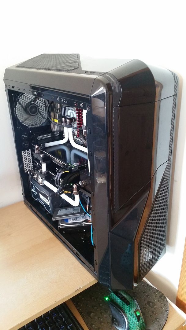
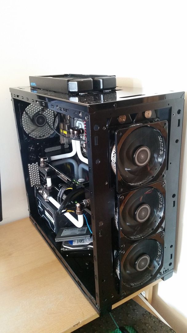
This is how she stands today;
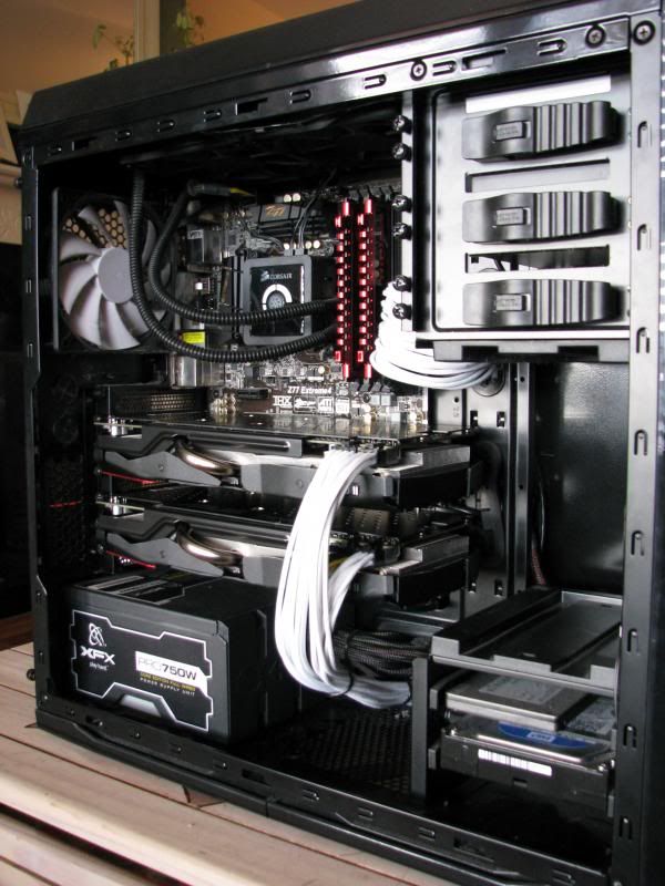
The only difference is I have an EVGA Supernova G2 1000w PSU in there now instead of the XFX 750w.
The vital stats,
3570k.
Two Asus r9 290's in crossfire.
Both currently stock clocks as on stock cooling but I had the CPU OC'd to 4.5ghz for the better part of a year and a half until my H100 died a while back.
A black NZXT Phantom 410.
Into which I plan to fit two radiators. A 30mm thick 240mm Alphacool NexXxoS ST30 on top and a 45mm thick 360mm Alphacool NexXxoS XT45 in the front.
To fit the front rad I will be removing the lower HDD cage and the 5.25" drive bays on top. The 240mm rad on top will be configured push and the 360 in front will be push pull. To which I will add 9 Enermax TB Silence PWM fans. 8 for the rads, actually 7 for the rads, more on that later, and one as a stand alone exhaust.
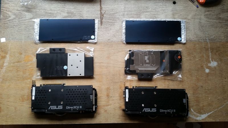
I have an EK Xres 140 D5 PWM pump and res combo which will be mounted onto the back of the 360mm rad and a pair of EK blocks for both the 290's and an EK Supremacy CPU block.
The pump and all fans will be PWM controlled (hopefully) via a custom made 10 way PWM splitter PCB I managed to get off some guy in the UK. He made a handful as a project and flogged em on eBay afterwards.
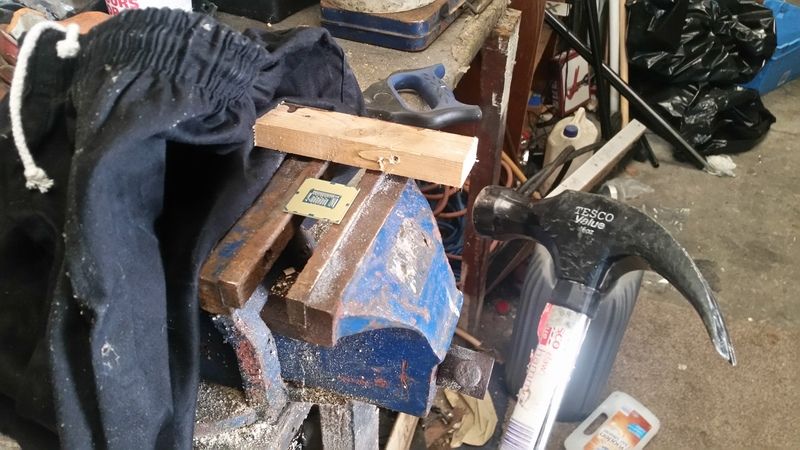
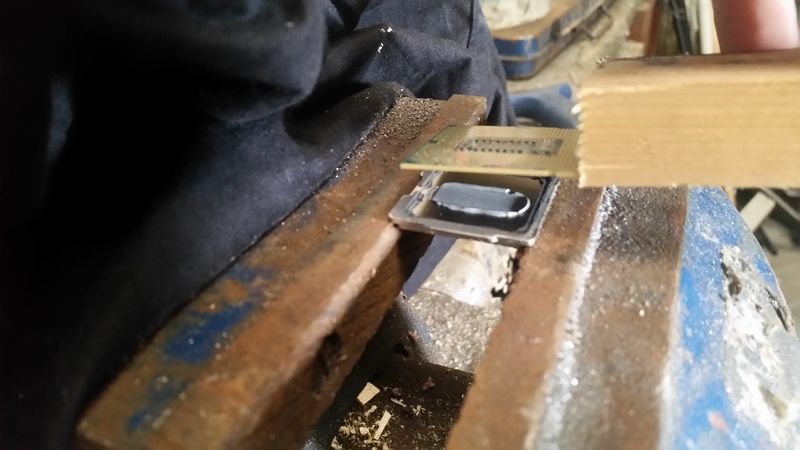
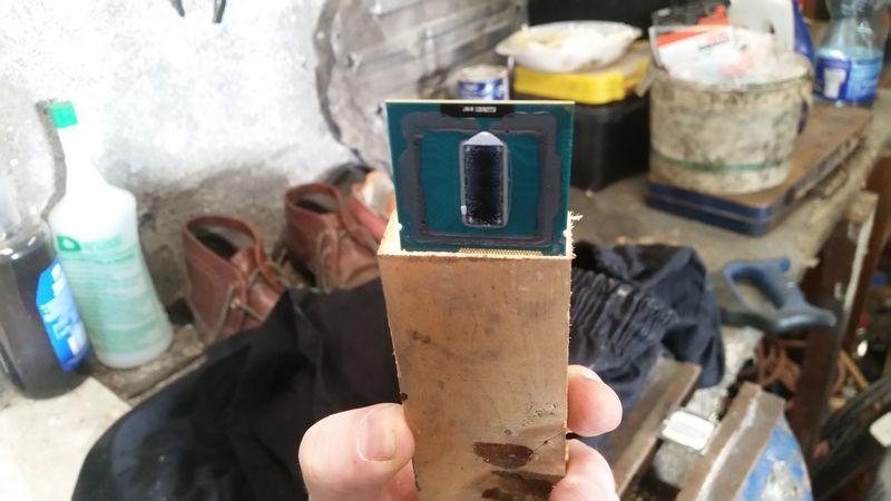
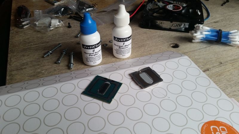
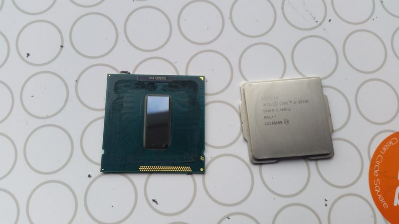
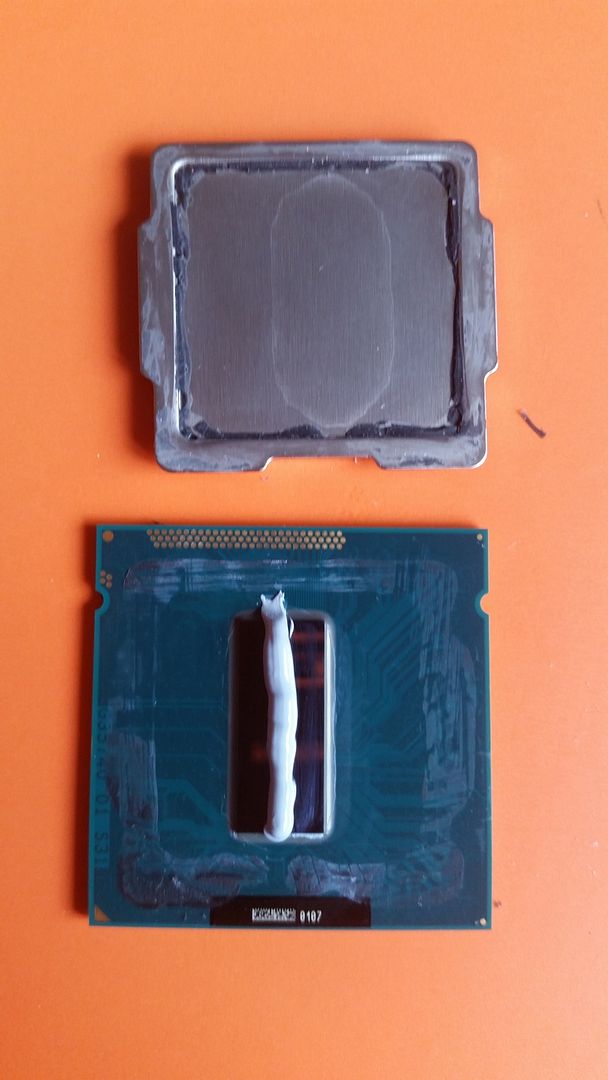
I plan to delid the 3570k also and originally had planned a full set of custom cables but I'm not 100% on that at the mo cause I dunno if I can be arsed tbh! Oh, there'll also be an obligatorey window mod to follow as well!
So, without further adieu, onto the nitty gritty of ot all!
I spent a few hours at today, stripping down to old build test fitting a few pieces and have already hit several snags. Details in the pics below.
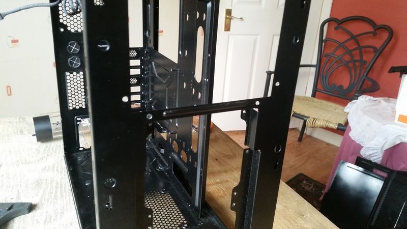
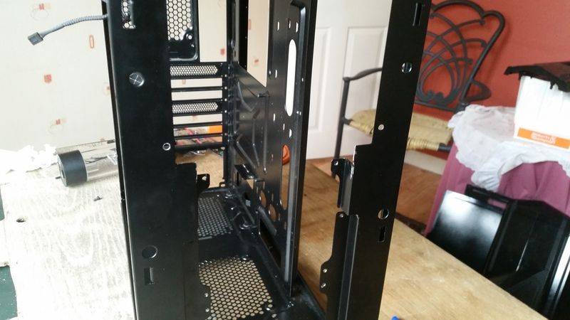
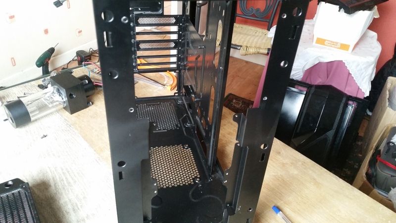
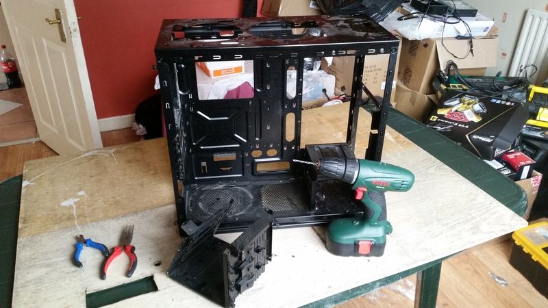
Stage one, after stipping down the existing build I set to work on those useless 5.25" bays. A few minutes work with a drill and a long nose pliers and those rivets are outta there.
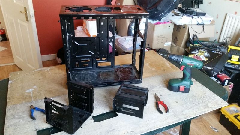
Followed shortly thereafter by the HDD cage below.
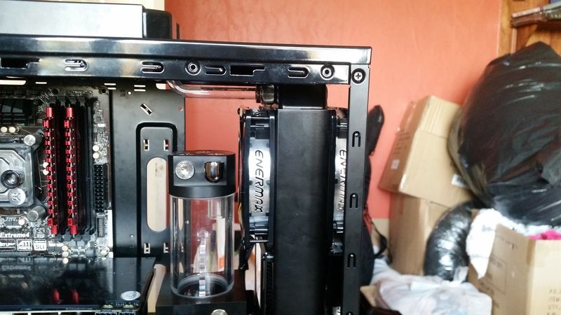
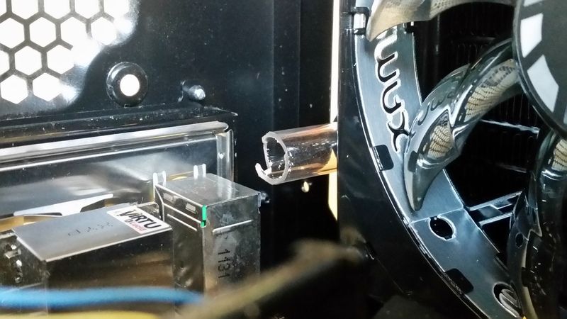
Now to test fit a few pieces. My first concern was having the radiator ports from the 240 rad on top, at the back of the case. I thought there would be clearence issues with motherboard heatsinks or the I/O panel.
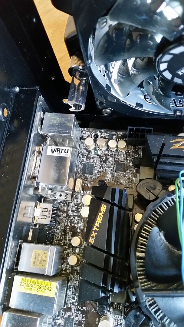
Luckily however, there is not. It only fits by a couple of millimetres, but it's plenty!
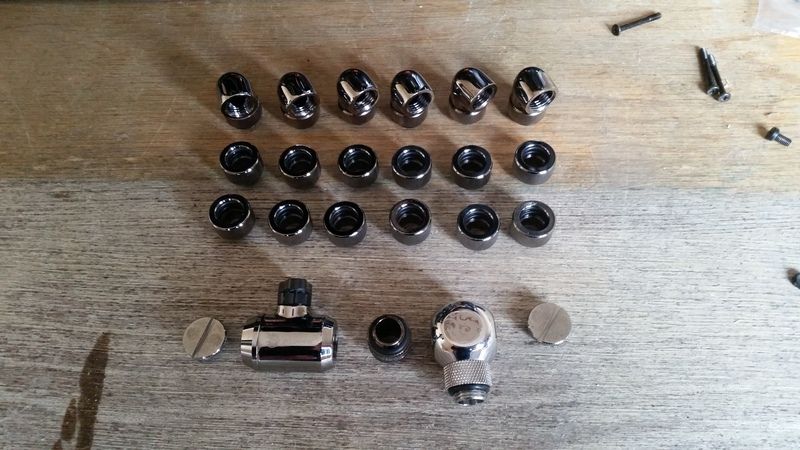
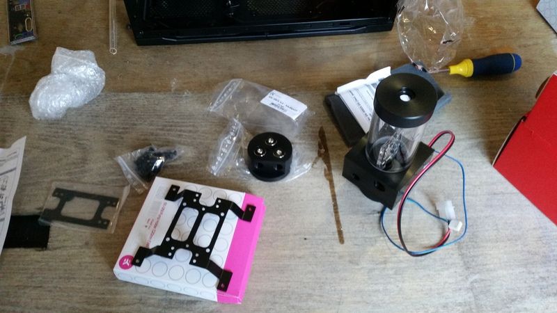
Next job was to assemble the pump. I have a multi port top, additional mounting brackets and a dress up kit to install.
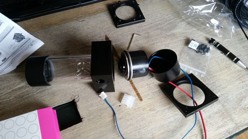
The additional pump cover tidies everything up nicely.
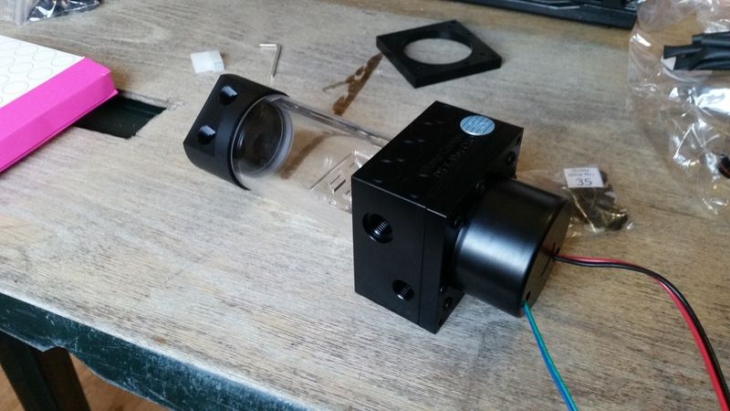
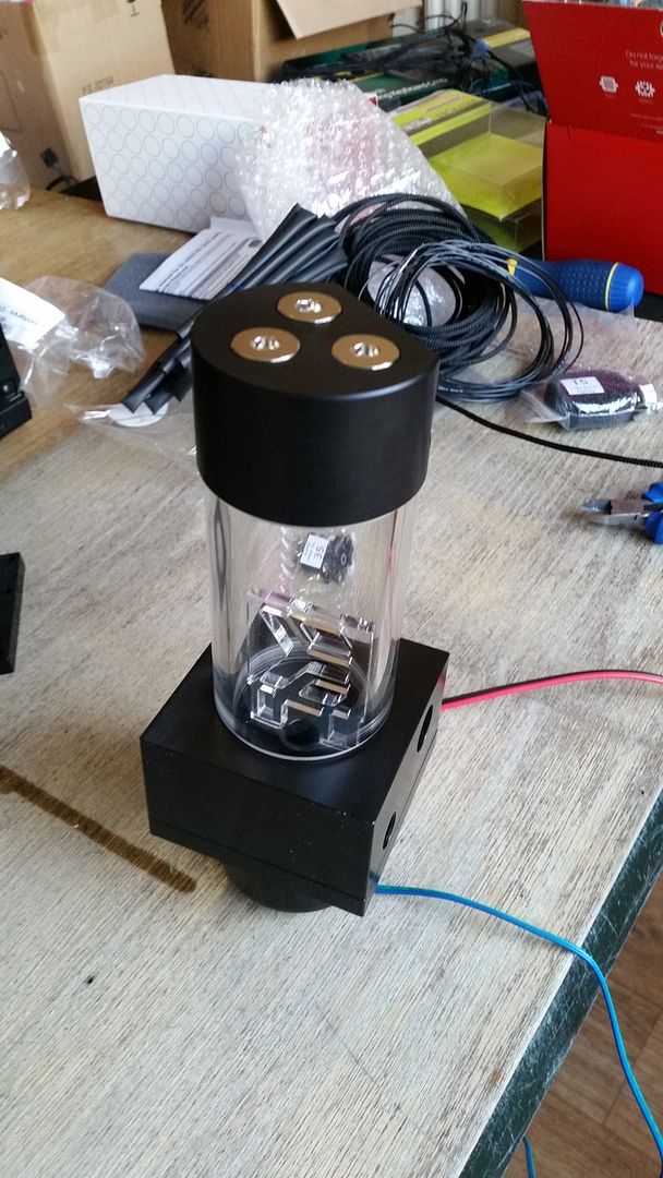
So the first snag I hit was the additional mounting plate I bought from EK so I could mount the pump and res vertically on the back of the radiator is drilled for 4mm bolts. The tapped holes on the rads are only 3mm so they had to be widened.
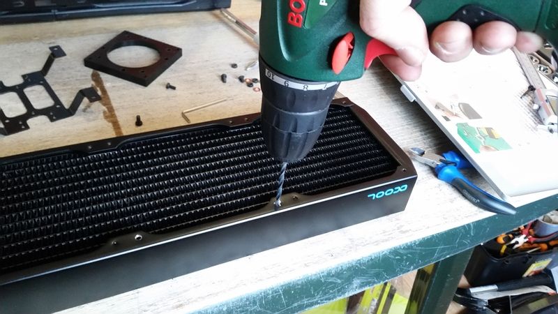
I tried to get all engineery and use the tap and die set I bought from Aldi for €20 to tap 4mm threads into the newly widened holes.
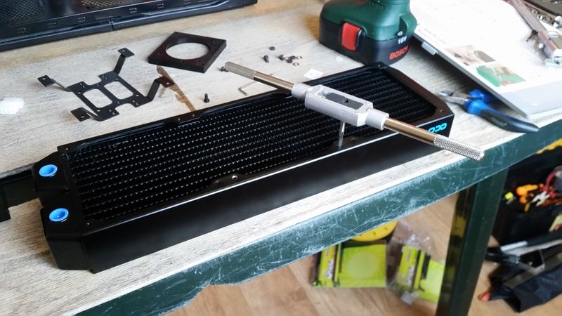
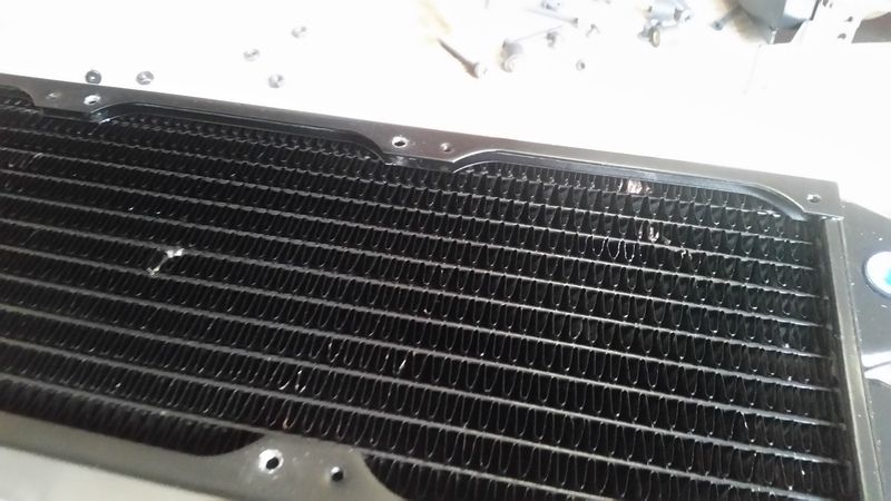
And proceeded to drop the tap handle directly onto the rad and damage some of the fins!
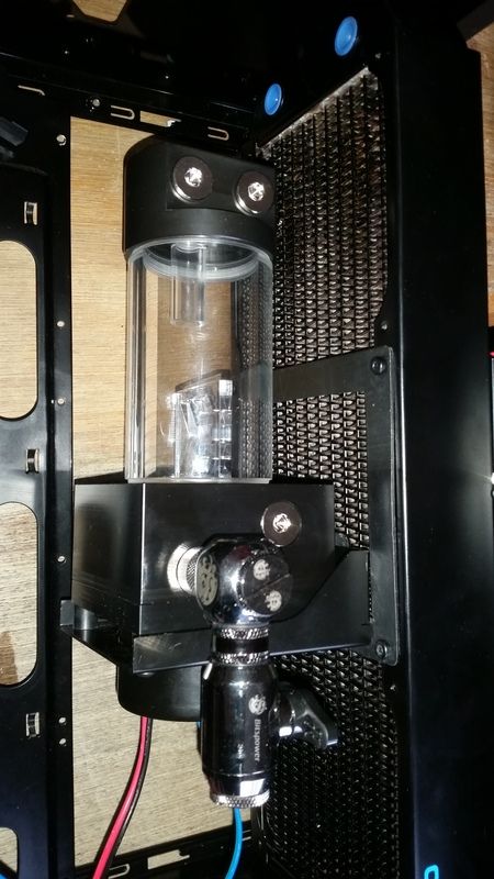
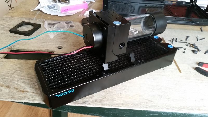
The pump wit all the accessories fully assembled and mounted to the rad. Looks like some sort of future tank!
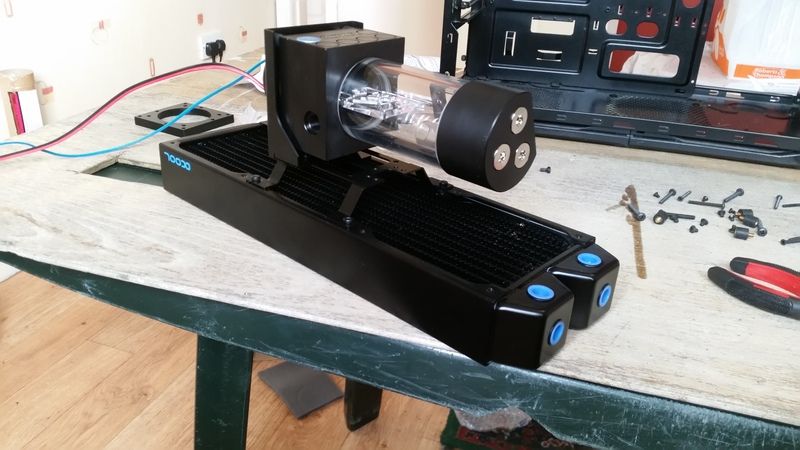
Or maybe some sort of laser cannon, I can't decide!
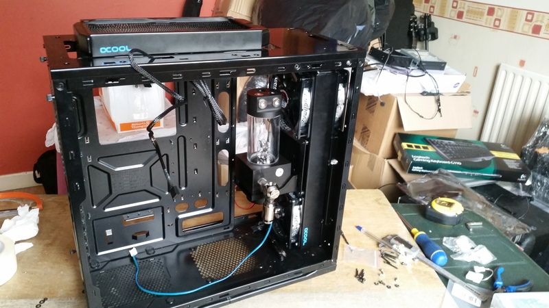
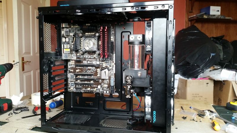
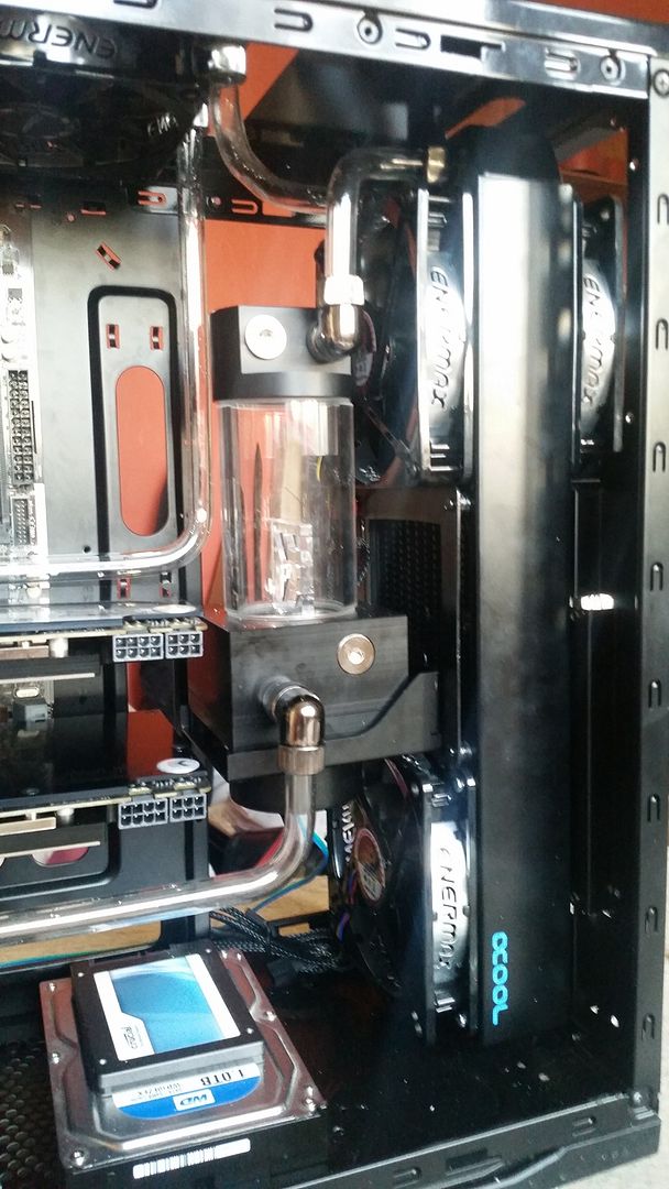
But at last, here she is installed into the case. Looks pretty sweet!
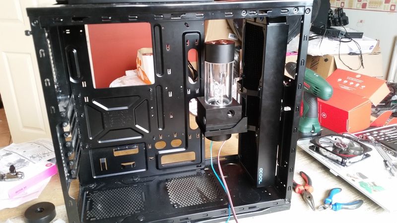
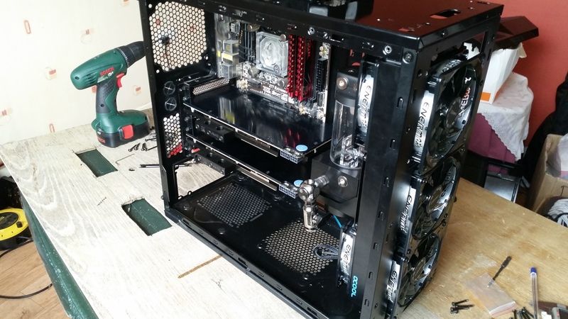
My chuffedness is short lived however as we have just hit snag number two. The GPUs will not fit with the above config. The PCB is about 5mm too long. ****.
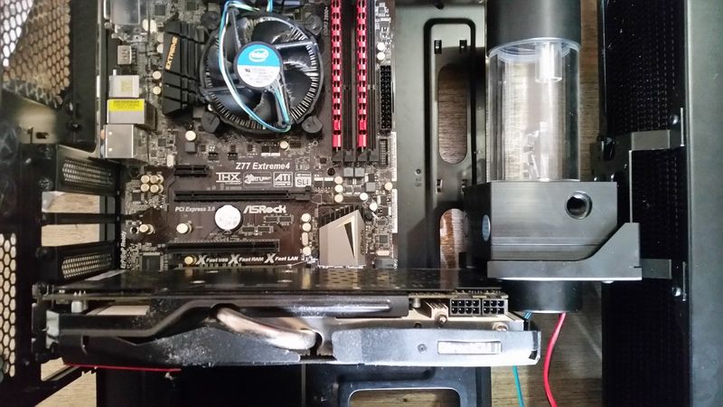
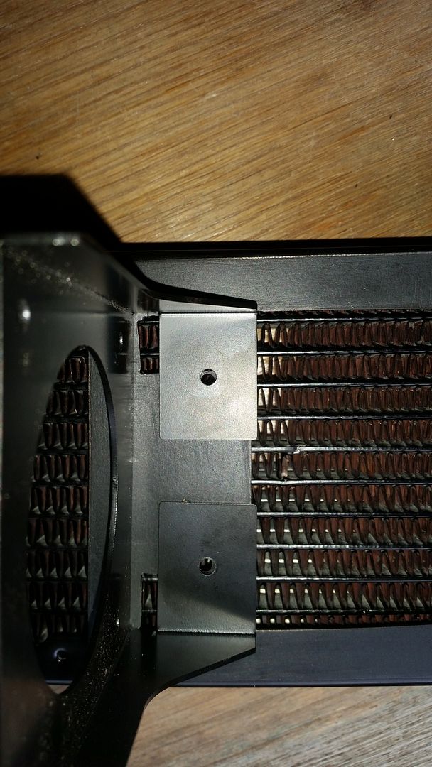
I suspected I may have had trouble here which is why the 360 rad is not fully push pull. I will be leaving off the middle pull fan to make way for the res. But look at all that wasted space behind the bracket between the res and the rad. There must be 20mm in there easily.
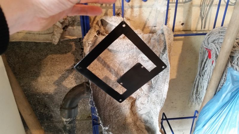
I decided I would have to scrap the bracket and try make something myself so I called out to my Dads and had a route around his garage and found this. Not sure what it is, a cassette tape display for a shop maybe but it's 1.5mm steel and black, happy days! I taped off a section and marked out a 120x120mm square.
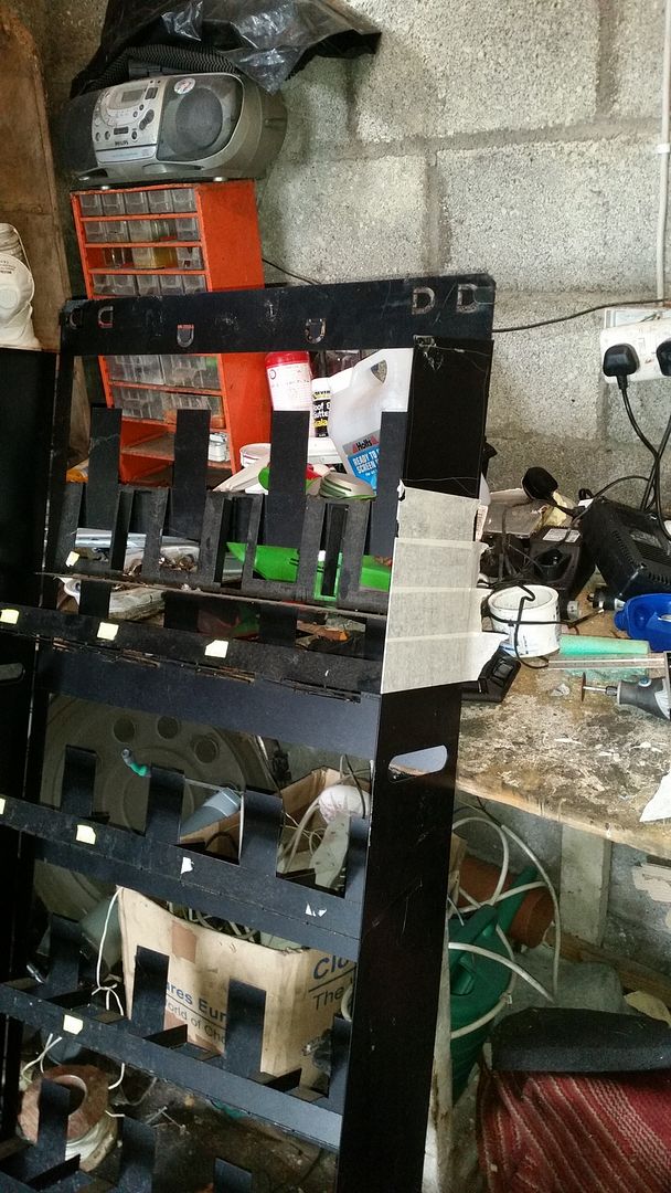
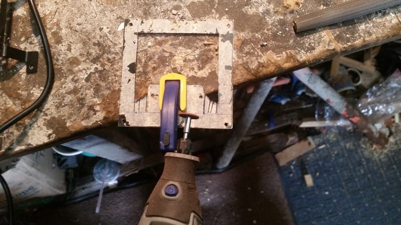
Time to break out the Dremmel!
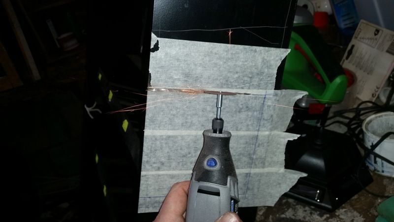
Slowly but surely, getting there.
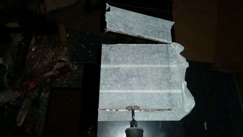
And it's free!
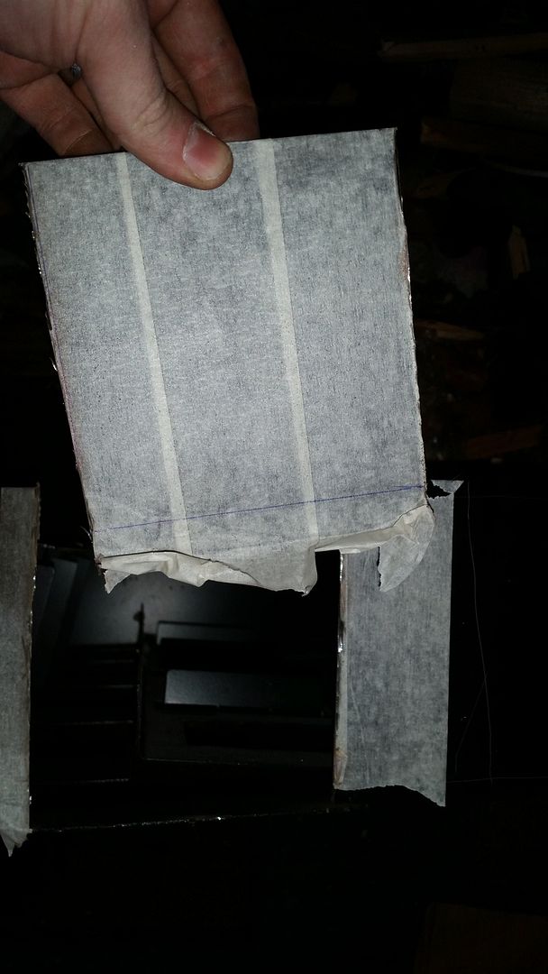
A hacksaw made light work of the remaining side. So much faster than the Dremmel it's hard to believe!
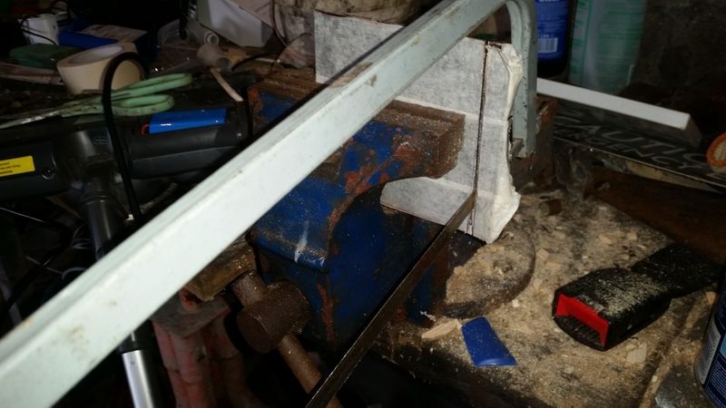
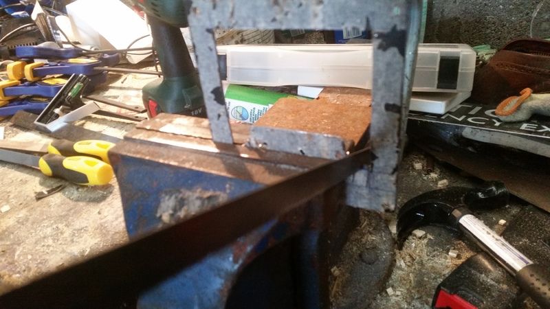
Now to straighten out those edges. I just took my time, teasing my way up to the line.
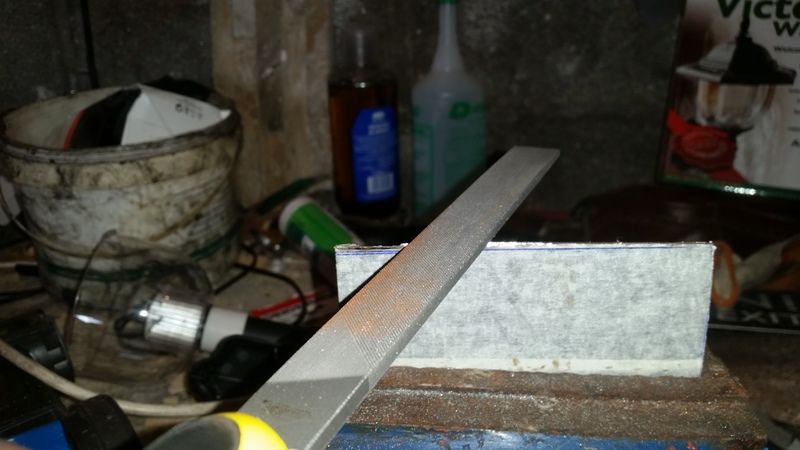
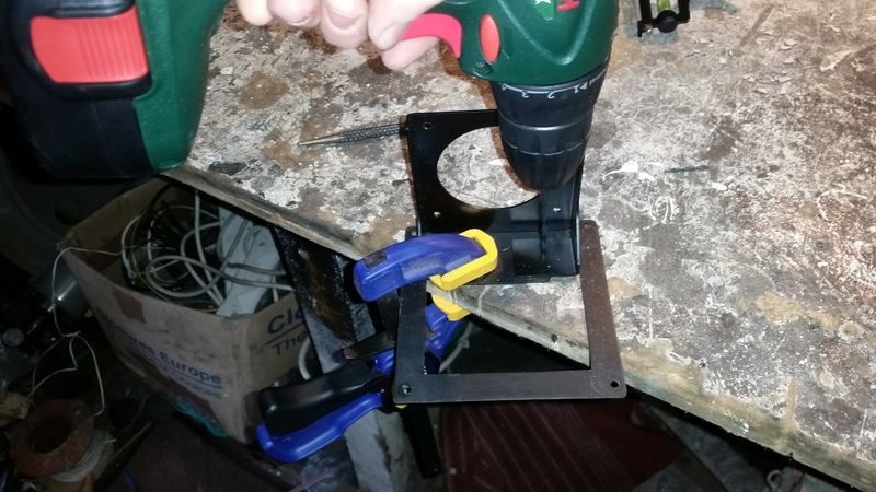
With the edges straightened out, I clamped the EK bracket onto my work piece to use as a template to make out the holes. As some of my woodworking friends always say, "You can never have enough clamps!"
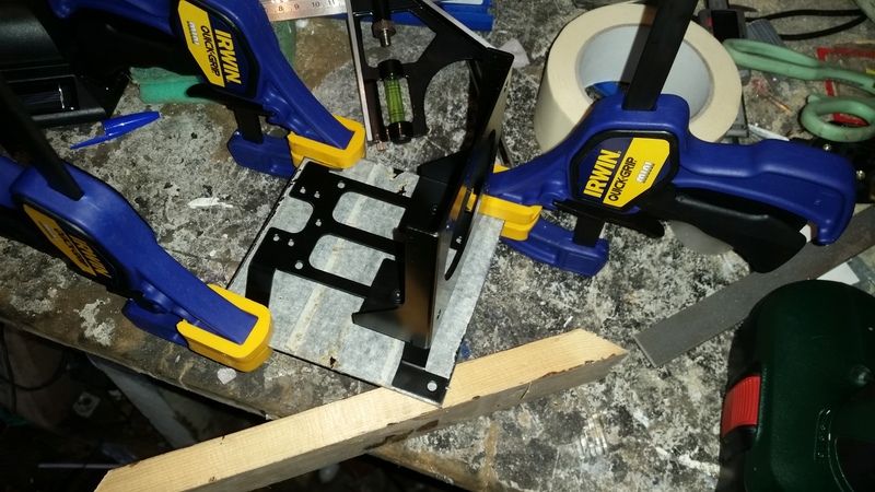
Again using the original part as a template and marking out the holes for the pump holder.
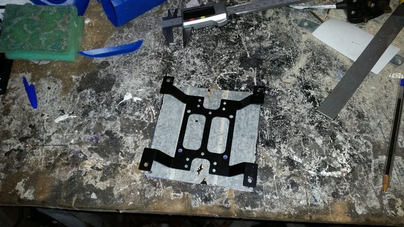
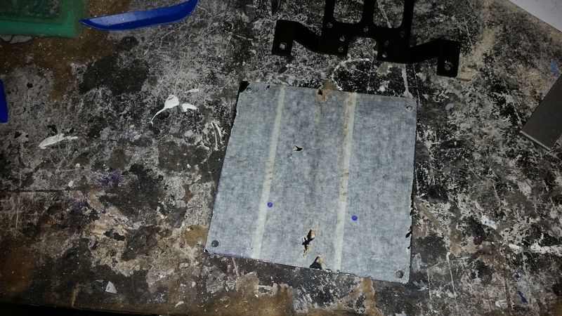
All holes drilled.
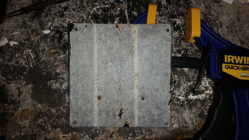
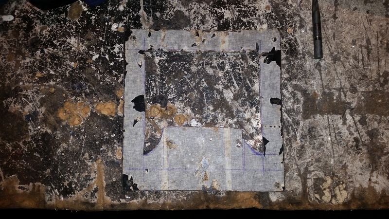
Now to mark out interior to be removed and come up with some sort of design.
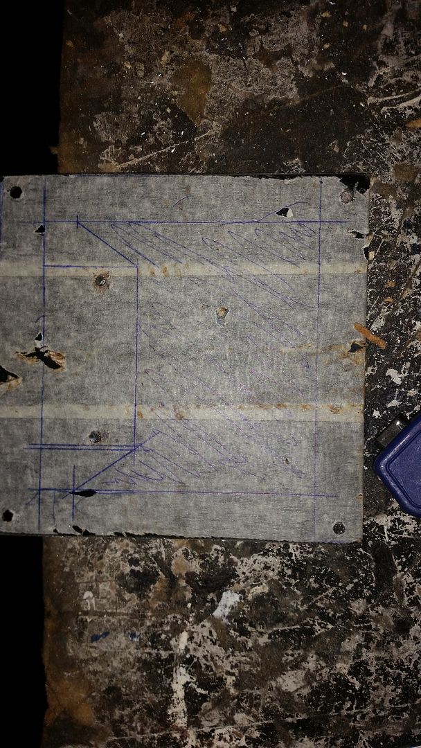
With the design drawn out, I drilled a few 8mm holes to try and make space to get the hacksaw blade in there to start removing the waste.
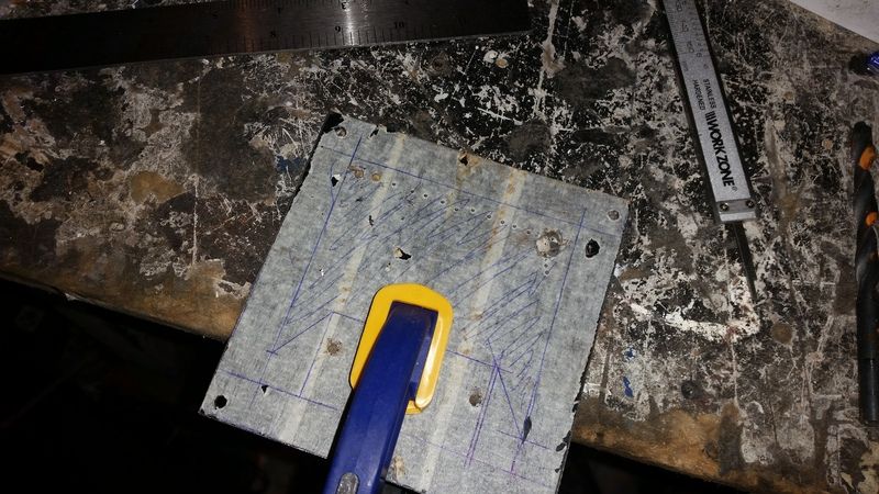
Most of the material has been removed here by now. To get tight down to the line, I just cut a series of shallow cuts at then came at them sideways to clear them out. It worked out quite well.
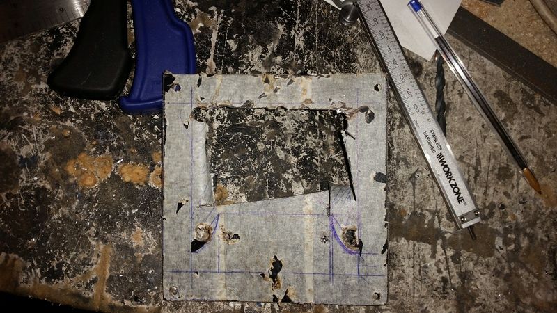
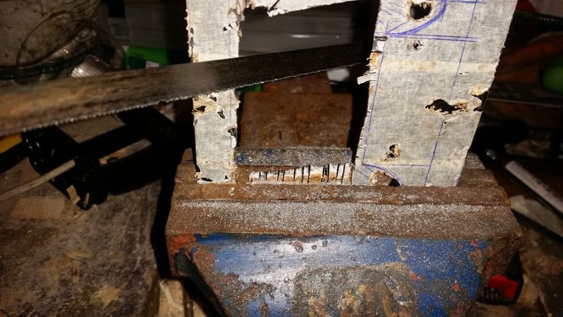
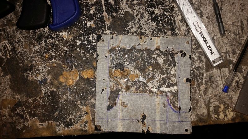
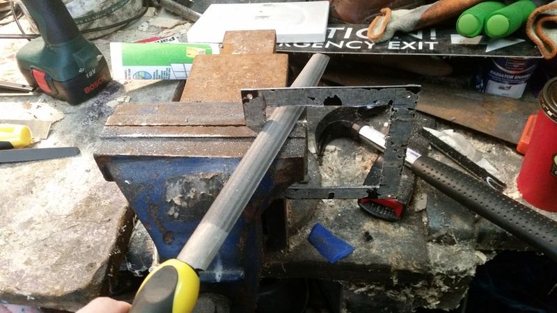
And then the filing began. And went on and on and on for about an hour!
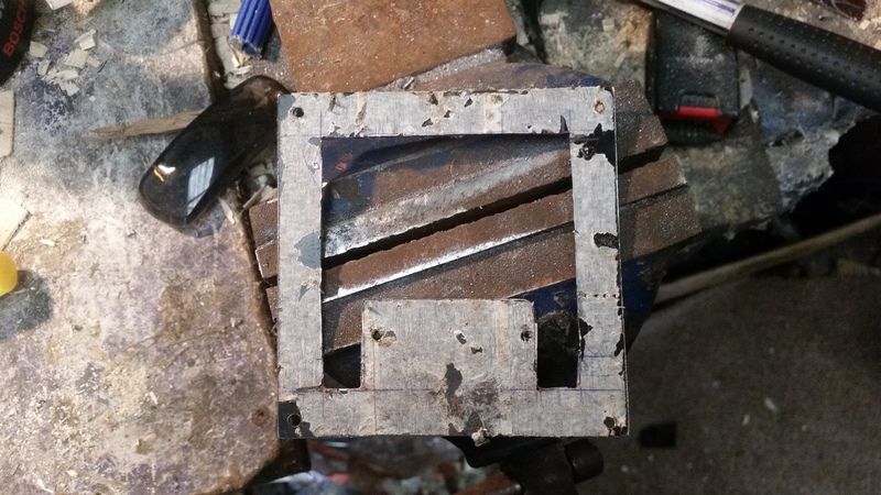
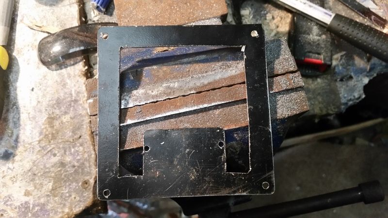
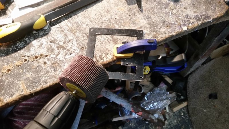
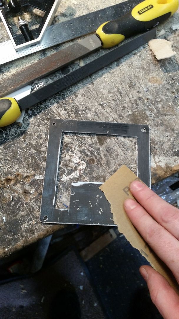
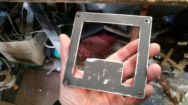
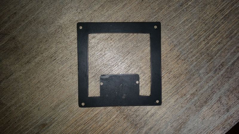
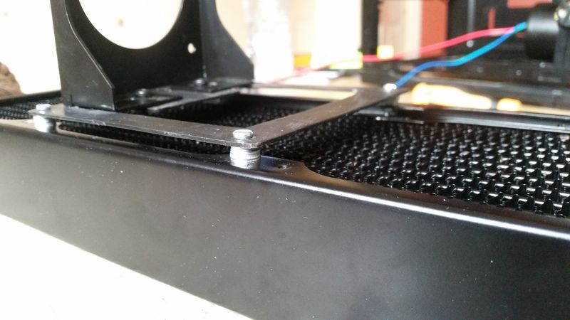
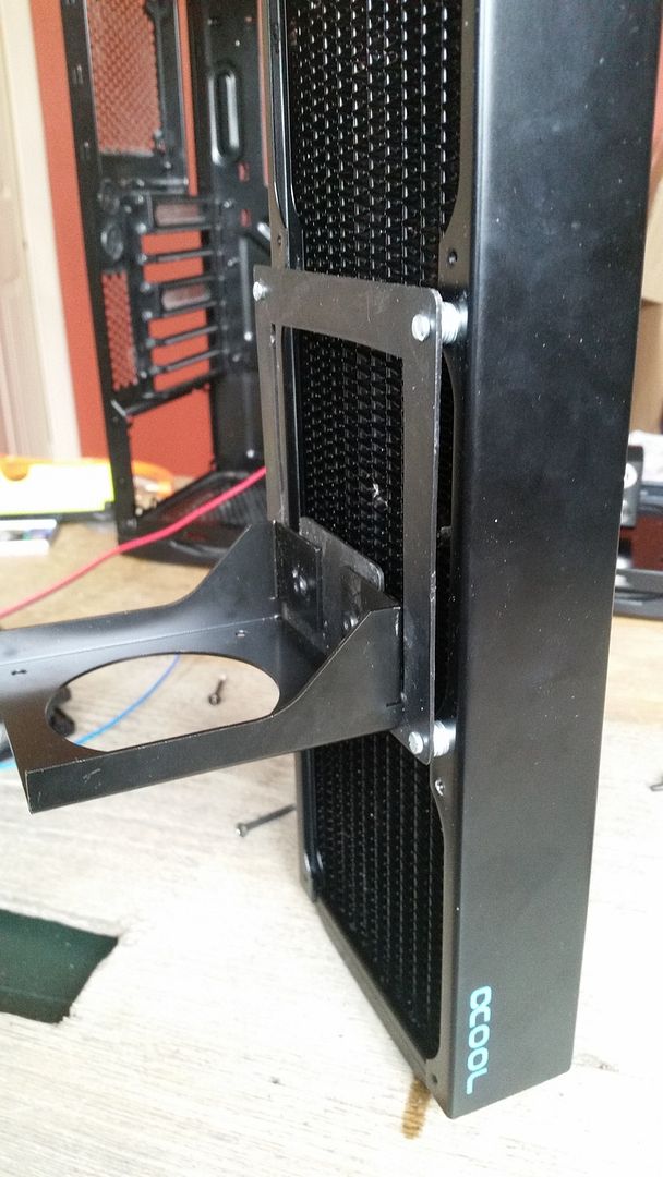
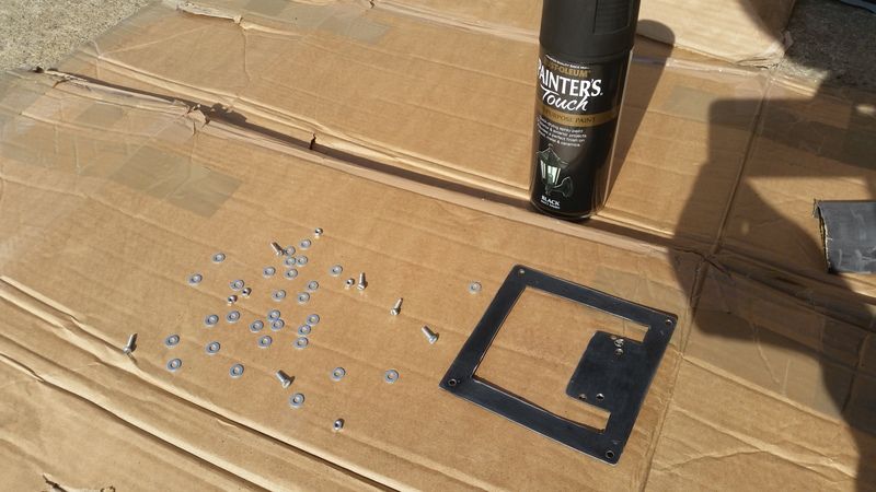
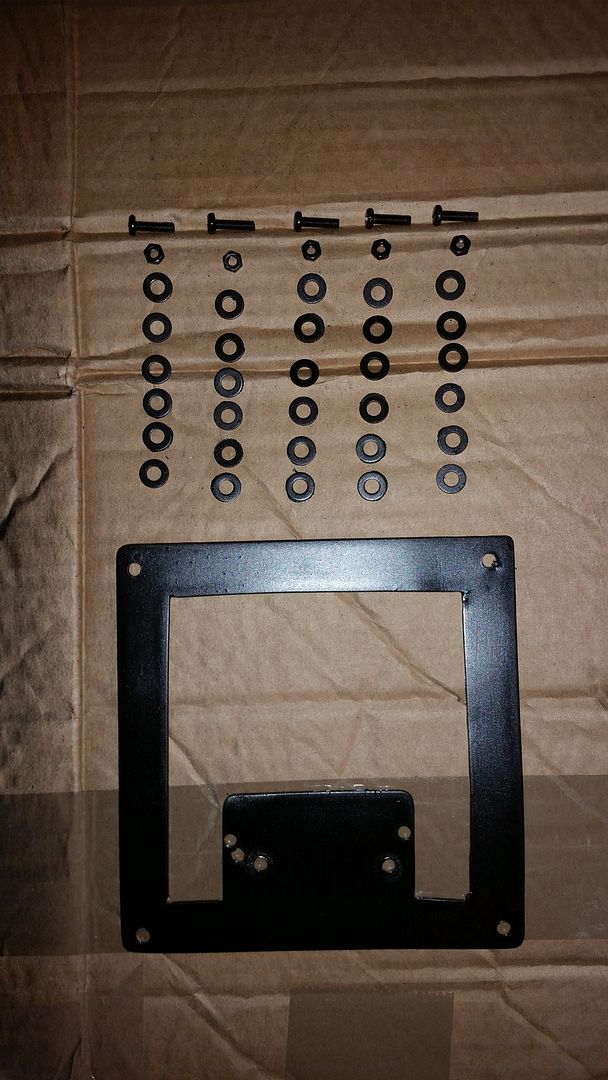
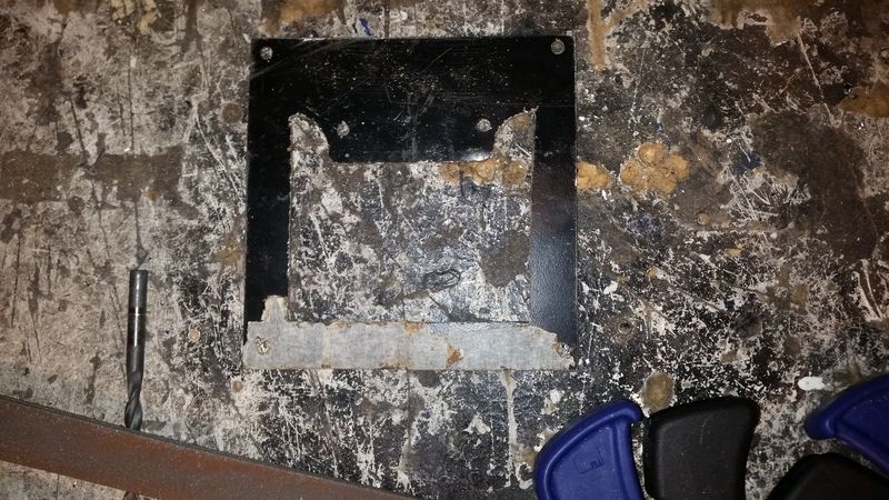
Finally here we are, not bad for a fella with no experience in metal fabrication and only hand tools! I'm not sure on the curves though, I thought they might look nice but I think I'm just gonna square them off tomorrow. I also need to square up a few places and then sand it all down and give it a spray paint, but for a bracket that will be difficult to see, I think it will do nicely.
And finally an obligatory beer! More to follow tomorrow, cheers!

The plan is to upgrade my watercool my current system as the 290s are far too hot, I need to set the GPU fans to 100% via Afterburner and turn all 7 case fans up to 12v just to maintain temps of high 80s! Some games reach 94c where my cards start to thermally throttle by up to 20%.
Could I have done this cheaper and easier? Certainly, but where is the fun in that?!

This is how she stands today;

The only difference is I have an EVGA Supernova G2 1000w PSU in there now instead of the XFX 750w.
The vital stats,
3570k.
Two Asus r9 290's in crossfire.
Both currently stock clocks as on stock cooling but I had the CPU OC'd to 4.5ghz for the better part of a year and a half until my H100 died a while back.
A black NZXT Phantom 410.
Into which I plan to fit two radiators. A 30mm thick 240mm Alphacool NexXxoS ST30 on top and a 45mm thick 360mm Alphacool NexXxoS XT45 in the front.
To fit the front rad I will be removing the lower HDD cage and the 5.25" drive bays on top. The 240mm rad on top will be configured push and the 360 in front will be push pull. To which I will add 9 Enermax TB Silence PWM fans. 8 for the rads, actually 7 for the rads, more on that later, and one as a stand alone exhaust.
I have an EK Xres 140 D5 PWM pump and res combo which will be mounted onto the back of the 360mm rad and a pair of EK blocks for both the 290's and an EK Supremacy CPU block.
The pump and all fans will be PWM controlled (hopefully) via a custom made 10 way PWM splitter PCB I managed to get off some guy in the UK. He made a handful as a project and flogged em on eBay afterwards.
I plan to delid the 3570k also and originally had planned a full set of custom cables but I'm not 100% on that at the mo cause I dunno if I can be arsed tbh! Oh, there'll also be an obligatorey window mod to follow as well!
So, without further adieu, onto the nitty gritty of ot all!
I spent a few hours at today, stripping down to old build test fitting a few pieces and have already hit several snags. Details in the pics below.
Stage one, after stipping down the existing build I set to work on those useless 5.25" bays. A few minutes work with a drill and a long nose pliers and those rivets are outta there.

Followed shortly thereafter by the HDD cage below.

Now to test fit a few pieces. My first concern was having the radiator ports from the 240 rad on top, at the back of the case. I thought there would be clearence issues with motherboard heatsinks or the I/O panel.

Luckily however, there is not. It only fits by a couple of millimetres, but it's plenty!

Next job was to assemble the pump. I have a multi port top, additional mounting brackets and a dress up kit to install.

The additional pump cover tidies everything up nicely.


So the first snag I hit was the additional mounting plate I bought from EK so I could mount the pump and res vertically on the back of the radiator is drilled for 4mm bolts. The tapped holes on the rads are only 3mm so they had to be widened.

I tried to get all engineery and use the tap and die set I bought from Aldi for €20 to tap 4mm threads into the newly widened holes.

And proceeded to drop the tap handle directly onto the rad and damage some of the fins!


The pump wit all the accessories fully assembled and mounted to the rad. Looks like some sort of future tank!

Or maybe some sort of laser cannon, I can't decide!

But at last, here she is installed into the case. Looks pretty sweet!

My chuffedness is short lived however as we have just hit snag number two. The GPUs will not fit with the above config. The PCB is about 5mm too long. ****.

I suspected I may have had trouble here which is why the 360 rad is not fully push pull. I will be leaving off the middle pull fan to make way for the res. But look at all that wasted space behind the bracket between the res and the rad. There must be 20mm in there easily.
I decided I would have to scrap the bracket and try make something myself so I called out to my Dads and had a route around his garage and found this. Not sure what it is, a cassette tape display for a shop maybe but it's 1.5mm steel and black, happy days! I taped off a section and marked out a 120x120mm square.

Time to break out the Dremmel!

Slowly but surely, getting there.

And it's free!

A hacksaw made light work of the remaining side. So much faster than the Dremmel it's hard to believe!

Now to straighten out those edges. I just took my time, teasing my way up to the line.

With the edges straightened out, I clamped the EK bracket onto my work piece to use as a template to make out the holes. As some of my woodworking friends always say, "You can never have enough clamps!"

Again using the original part as a template and marking out the holes for the pump holder.


All holes drilled.

Now to mark out interior to be removed and come up with some sort of design.

With the design drawn out, I drilled a few 8mm holes to try and make space to get the hacksaw blade in there to start removing the waste.

Most of the material has been removed here by now. To get tight down to the line, I just cut a series of shallow cuts at then came at them sideways to clear them out. It worked out quite well.


And then the filing began. And went on and on and on for about an hour!

Finally here we are, not bad for a fella with no experience in metal fabrication and only hand tools! I'm not sure on the curves though, I thought they might look nice but I think I'm just gonna square them off tomorrow. I also need to square up a few places and then sand it all down and give it a spray paint, but for a bracket that will be difficult to see, I think it will do nicely.

And finally an obligatory beer! More to follow tomorrow, cheers!

Last edited:


