Soldato
To save spamming up the What retro things have you done today? Thread, and as suggested, I'm creating threads for each Restoration and Upgrade logs.
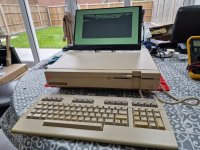
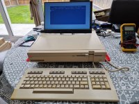
Source: Ebay - £130 advertised as having been previously repaired (by a little known youtuber) who sorted out a PSU issue, however the seller said the PSU issue has returned and it blew his RCD, so sold it as spares/parts. The photos made it look in OK condition, almost 'good' and had the keyboard intact and from what I could see no major damage to the case.
Plans
- Try to get it working, PSU first, then mainboard, then 1571
- Use the RGBtoHDMI that just arrived to check the 80 col mod direct to a monitor (excited to see this pixel perfect on a HDMI display!)
- Clean, clean and more clean!
- repair any minor plastic issues (broken tabs etc)
- c0pperdragon YUV mod so I can get perfect HDMI 40 col/C64 mode output.
- VDC memory upgrade
- Install function ROM (GEOS)
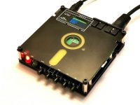
- If I can get the 1571 going, it came with about 40-50 floppies, so would like to dump those to some device that can store them on SD Card, you never know the treasures you may unearth!
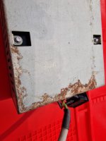
Condition on arrival - Not so good (PICS to follow) - 5/10? broken tab on the front panel, tiny crack on a corner and two tiny chunks out the sides. Opened up and wow.. dust/fluff etc everywhere and the worst part, major corrosion (to the point of rust) on the metal work..
Immediate Jobs:
I'll update this and carry on as I go!
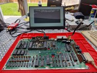
I'm just getting setup for a quick PCBA Clean.
I am thinking, ESD soft bristle brushes, contact cleaner and IPA and that'll probably shift the easy stuff.
I will check in work and measure the ultrasonic cleaners, if they had a larger 30L one, that main board would fit in, maybe if I get it working, then I could invest some time in giving it an ultrasonic clean..
Source: Ebay - £130 advertised as having been previously repaired (by a little known youtuber) who sorted out a PSU issue, however the seller said the PSU issue has returned and it blew his RCD, so sold it as spares/parts. The photos made it look in OK condition, almost 'good' and had the keyboard intact and from what I could see no major damage to the case.
Plans
- Try to get it working, PSU first, then mainboard, then 1571
- Use the RGBtoHDMI that just arrived to check the 80 col mod direct to a monitor (excited to see this pixel perfect on a HDMI display!)
- Clean, clean and more clean!
- repair any minor plastic issues (broken tabs etc)
- c0pperdragon YUV mod so I can get perfect HDMI 40 col/C64 mode output.
- VDC memory upgrade
- Install function ROM (GEOS)
- If I can get the 1571 going, it came with about 40-50 floppies, so would like to dump those to some device that can store them on SD Card, you never know the treasures you may unearth!
Condition on arrival - Not so good (PICS to follow) - 5/10? broken tab on the front panel, tiny crack on a corner and two tiny chunks out the sides. Opened up and wow.. dust/fluff etc everywhere and the worst part, major corrosion (to the point of rust) on the metal work..
Immediate Jobs:
- Taking the case off revealed a missing screw holding the PSU in , should be easy to source.
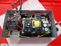
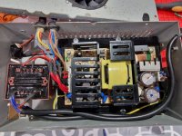
- Opening the PSU revealed a box of horrors:
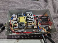
The youtubers repair took the original PSU out (shame they didn't try to fix it, it's a 5V SMPS , 12V Linear + 9V unregulated AC and quite reliable..
However, it's a known 'thing' to rip it out and replace with a 12v/5v dual output SMPS module and a small transformer for the 9v AC..
Note 3 things
1. The dual output SMPS is at a jaunty angle.. That's because the mounting method was to cut in half those cupboard corner plastic brackets you use to reinforce Ikea tat, then epoxy those to the floor of the PSU case and then use self tappers to screw the module to the plastic brackets... However, 3 of the plastic brackets have come away from the epoxy and the remaining one only had the screw half way in, so the board is pivoting/flapping around..
2. In the bottom middle, just under the right hand plastic bracket, there looks like a brown wire going down to the large square hole at the bottom, that is actually earth braid (exposed copper) which was required to earth the SMPS module to the case, however, as the SMPS module was flapping around, I am confident that has been shorting the output stage.
3. The mains in, especially to the 9V transformer is rather weedy.. I guess the rationale was that since it uses bugger all power, a thin cable would do.. however, on inspecting the IEC lead supplied and checked the fuse... 13A.. so had the primary somehow shorted to ground, those weedy cables would have got a bit toasty with 13A flowing through them!
- The immediate task was extricate the SMPS module (Mean Well RPD-75A - A medical grade 75W module, actually a nice choice).
- Checking input and output connections for shorts and poking around a few components to check for anything obviously blown/open/short and I couldn't find anything..
- I decided to tentatively power it up unloaded, with a 3A fuse in the IEC lead, and retiring to the other end of an extension cable to switch on.. and... nothing.. dead..
- With the DMM, I started to trace the incoming AC and see where it went.. very quickly I found the radial non-resettable fuse on the neutral was blown..
- Powering off and ensuring caps had discharged, I poked around downstream of the fuse and everything seemed intact. My DMM does a good job of measuring caps in circuit and everything was bang on.
In work today (working for a medical device company is handy when I have access to some pretty bright people), they persuaded me that the PSU was worth saving and actually from the specs and 2 MOPP isolation sounded like a good thing..
- I couldn't find any compatible radial fuses in work, so the plan was... BODGE.. a bit of thin wire across the fuse, worse case would be 3A before the mains plug fuse would blow..
- On re-soldering the neutral to the connector crimp (I am glad I didn't do this in work, the lecture about crimps vs soldering would have been ringing in my ears for days!), I plugged it in, switched it on, and... no bang... and the output LED lit up!
- Checking the unloaded 5v and 12v outputs and they are spot on! Result..
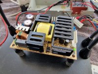
- The rest of the unit needs stripping/cleaning and checking a bit more before I want to apply power, so..
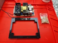
- Using Onshape, I've whipped up a PSU carrier that will allow me to use the old PSU threaded holes to hold a carrier, which will have 4 x heat staked threaded inserts to mount the SMPS Module:
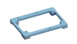
It'll be a bit clearer once printed and installed, but should be a good solution and will not rely on epoxy, although, I've not relied on threaded inserts for something critical like this, but everyone thinks I'm over engineering it as-is.. It will be earthed to the PSU case, so worth a shot.
The 3D Printer is fired up and just started the print, which will take 4 hours.. I have ordered some M3 inserts for tomorrow as I only have M4 and M5 which are too large.
- Opening the PSU revealed a box of horrors:

The youtubers repair took the original PSU out (shame they didn't try to fix it, it's a 5V SMPS , 12V Linear + 9V unregulated AC and quite reliable..
However, it's a known 'thing' to rip it out and replace with a 12v/5v dual output SMPS module and a small transformer for the 9v AC..
Note 3 things
1. The dual output SMPS is at a jaunty angle.. That's because the mounting method was to cut in half those cupboard corner plastic brackets you use to reinforce Ikea tat, then epoxy those to the floor of the PSU case and then use self tappers to screw the module to the plastic brackets... However, 3 of the plastic brackets have come away from the epoxy and the remaining one only had the screw half way in, so the board is pivoting/flapping around..
2. In the bottom middle, just under the right hand plastic bracket, there looks like a brown wire going down to the large square hole at the bottom, that is actually earth braid (exposed copper) which was required to earth the SMPS module to the case, however, as the SMPS module was flapping around, I am confident that has been shorting the output stage.
3. The mains in, especially to the 9V transformer is rather weedy.. I guess the rationale was that since it uses bugger all power, a thin cable would do.. however, on inspecting the IEC lead supplied and checked the fuse... 13A.. so had the primary somehow shorted to ground, those weedy cables would have got a bit toasty with 13A flowing through them!
- The immediate task was extricate the SMPS module (Mean Well RPD-75A - A medical grade 75W module, actually a nice choice).
- Checking input and output connections for shorts and poking around a few components to check for anything obviously blown/open/short and I couldn't find anything..
- I decided to tentatively power it up unloaded, with a 3A fuse in the IEC lead, and retiring to the other end of an extension cable to switch on.. and... nothing.. dead..
- With the DMM, I started to trace the incoming AC and see where it went.. very quickly I found the radial non-resettable fuse on the neutral was blown..
- Powering off and ensuring caps had discharged, I poked around downstream of the fuse and everything seemed intact. My DMM does a good job of measuring caps in circuit and everything was bang on.
In work today (working for a medical device company is handy when I have access to some pretty bright people), they persuaded me that the PSU was worth saving and actually from the specs and 2 MOPP isolation sounded like a good thing..
- I couldn't find any compatible radial fuses in work, so the plan was... BODGE.. a bit of thin wire across the fuse, worse case would be 3A before the mains plug fuse would blow..
- On re-soldering the neutral to the connector crimp (I am glad I didn't do this in work, the lecture about crimps vs soldering would have been ringing in my ears for days!), I plugged it in, switched it on, and... no bang... and the output LED lit up!
- Checking the unloaded 5v and 12v outputs and they are spot on! Result..

- The rest of the unit needs stripping/cleaning and checking a bit more before I want to apply power, so..
- Using Onshape, I've whipped up a PSU carrier that will allow me to use the old PSU threaded holes to hold a carrier, which will have 4 x heat staked threaded inserts to mount the SMPS Module:

It'll be a bit clearer once printed and installed, but should be a good solution and will not rely on epoxy, although, I've not relied on threaded inserts for something critical like this, but everyone thinks I'm over engineering it as-is.. It will be earthed to the PSU case, so worth a shot.
The 3D Printer is fired up and just started the print, which will take 4 hours.. I have ordered some M3 inserts for tomorrow as I only have M4 and M5 which are too large.
Largely TBD at the moment..
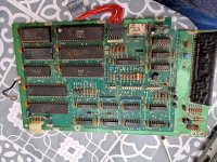
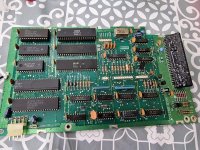
1571 Drive PCBA
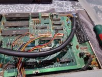
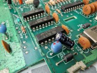
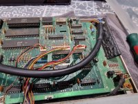
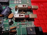
the solder resist has oxidised in places... A quick continuity check across 50 or so tracks shows they are all seemingly intact..
I've just done some spot checking with White Vinegar for the rust and then IPA and the oxidisation on the resist will be staying, you could scrape it off somewhat, but it's too easy to go through to the trace underneath.
It's a bit of a shame, I really wanted this one to be in tip top condition by the time I'd finished and there is no way that PCBA is going to look pretty..
I'm resisting the temptation to get a better condition one of eBay, there are a couple on now for parts/spares that look tidy, but they are more than I paid for the entire computer!
The other tempting eBay upgrade would be a very clean, non yellowed and very intact C128D Case, but that will cost almost the same as the entire computer, however it would at least make it look good from the outside!
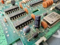
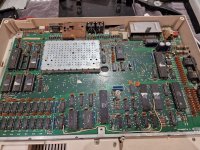
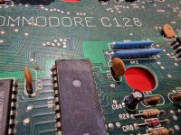
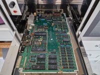
The Main PCBA is a bit better, although the RF shield looks horrific, that will go at some point, awaiting the soon to be released c0pperdragon YUV solution that is alledgedly a lot easier than his last one..
And doing a bit of a quick continuity check on what look to be heavily oxidised areas show it's all intact.
1571 Drive PCBA

the solder resist has oxidised in places... A quick continuity check across 50 or so tracks shows they are all seemingly intact..
I've just done some spot checking with White Vinegar for the rust and then IPA and the oxidisation on the resist will be staying, you could scrape it off somewhat, but it's too easy to go through to the trace underneath.
It's a bit of a shame, I really wanted this one to be in tip top condition by the time I'd finished and there is no way that PCBA is going to look pretty..
I'm resisting the temptation to get a better condition one of eBay, there are a couple on now for parts/spares that look tidy, but they are more than I paid for the entire computer!
The other tempting eBay upgrade would be a very clean, non yellowed and very intact C128D Case, but that will cost almost the same as the entire computer, however it would at least make it look good from the outside!
The Main PCBA is a bit better, although the RF shield looks horrific, that will go at some point, awaiting the soon to be released c0pperdragon YUV solution that is alledgedly a lot easier than his last one..
And doing a bit of a quick continuity check on what look to be heavily oxidised areas show it's all intact.

I'll update this and carry on as I go!
I'm just getting setup for a quick PCBA Clean.
I am thinking, ESD soft bristle brushes, contact cleaner and IPA and that'll probably shift the easy stuff.
I will check in work and measure the ultrasonic cleaners, if they had a larger 30L one, that main board would fit in, maybe if I get it working, then I could invest some time in giving it an ultrasonic clean..
Last edited:




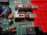
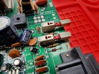
 That PSU was a complete bodge by the looks of it and very dangerous.