

Associate
- Joined
- 31 Jul 2012
- Posts
- 1,016
- Location
- Cheshire
Having seen some other arcade machine builds in this forum, I figured I'd post some details on my project. This has been built in a number of stages and was originally started in 2009 but finally completed a few months ago. As it's progressed, various sections have been re-done to make it look more like the original.
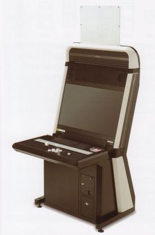
The design itself is based on a real world cabinet call the Vewlix. I'm always looking to accommodate new projects and have limited space so I elected to go for a 24 inch screen rather than a 32 inch like the original. I'm not usually fond of more modern arcade cabinet designs but the styling on the Vewlix is an exception to that. Given the reduced width, I have called this the Vewlix 'Slim'. It sports a single player panel like many of the originals. I may build another at some point for 2 player action but to be honest, my kids / friends aren't overly interested in the arcade games I play on this cabinet so it's not really an issue.
Some of the earlier pictures in this log are not great and were taken some time ago so apologies for that.
Completed project video tour:
Commercially available Vewlix cabinet:
I'll cover off a few details around the materials and tools used for the project. These were as follows:
Materials:
MDF
Wood strips
Screws
Cast acrylic (clear and opal)
Artwork (paper and vinyl
Leveling feet
4.1 sound system running in dual stereo
Sanwa stick and buttons
Hacked XBOX fightpad
High impact polystyrene
Blackboard vinyl
Speaker grilles
Paint and varnish
Aluminium strip
Tools:
Small B&D Workbench
Clamps
Router (flush trim and router bits)
Jigsaw
Power drill / driver
Foam roller
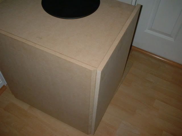
Base unit construction:
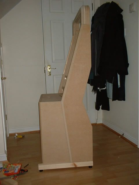
The main base unit was constructed to be the same width as the monitor with the front shaped to include a bevelled front piece. Lite the original, it's not just a box and has a more interesting profile:
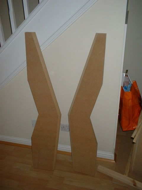
Side pieces:
The sides were measured and cut. Each side comprises a 12mm and 18mm section and are glued / screwed together. A chamfer bit was used to create the deep bevels on the sides.
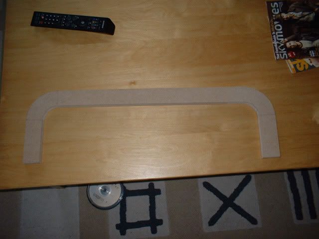
Top / Marquee section:
A lot of time was spent getting the curves as accurate as possible for the original piece. I'm a particularly great woodworker and have relatively little experience with it in general. After the original cuts, lots of sanding was required to get things as consistent as possible:
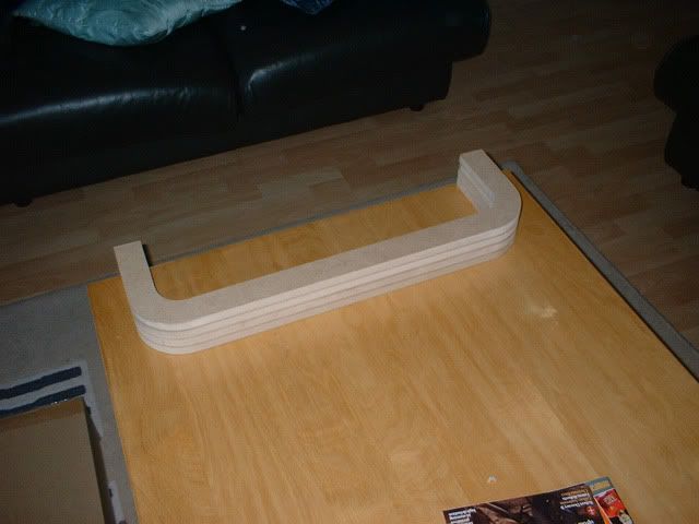
These were then cloned to make a stack:
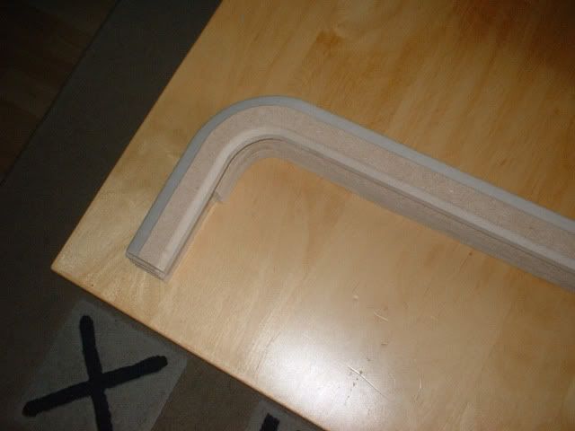
Various other cuts were made to these pieces to shape the front-most section and to allow for artwork to be inserted:
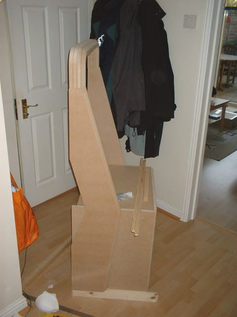
Basic cabinet assembly:
The top of the side pieces and the bottom of the marquee stac were cut at an angle to ensure the beveled edges on each lined up correctly. Piecs for the cabinet legs were also cut:
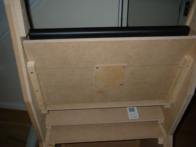
The legs were then shaped and self leveling feet screwed into them using threaded inserts. The main base unit sides were re-cut to ensure the side pieces lined up correctly with them. Bracing was used to join each if the sides together for stability purposes:
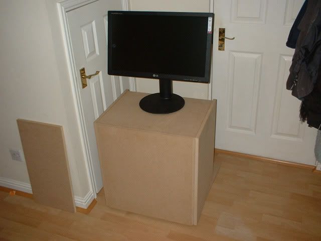
A Vesa mount was made for the monitor and screwed in place using simple wood batons:
The design itself is based on a real world cabinet call the Vewlix. I'm always looking to accommodate new projects and have limited space so I elected to go for a 24 inch screen rather than a 32 inch like the original. I'm not usually fond of more modern arcade cabinet designs but the styling on the Vewlix is an exception to that. Given the reduced width, I have called this the Vewlix 'Slim'. It sports a single player panel like many of the originals. I may build another at some point for 2 player action but to be honest, my kids / friends aren't overly interested in the arcade games I play on this cabinet so it's not really an issue.
Some of the earlier pictures in this log are not great and were taken some time ago so apologies for that.
Completed project video tour:
Commercially available Vewlix cabinet:

I'll cover off a few details around the materials and tools used for the project. These were as follows:
Materials:
MDF
Wood strips
Screws
Cast acrylic (clear and opal)
Artwork (paper and vinyl
Leveling feet
4.1 sound system running in dual stereo
Sanwa stick and buttons
Hacked XBOX fightpad
High impact polystyrene
Blackboard vinyl
Speaker grilles
Paint and varnish
Aluminium strip
Tools:
Small B&D Workbench
Clamps
Router (flush trim and router bits)
Jigsaw
Power drill / driver
Foam roller
Base unit construction:
The main base unit was constructed to be the same width as the monitor with the front shaped to include a bevelled front piece. Lite the original, it's not just a box and has a more interesting profile:


Side pieces:
The sides were measured and cut. Each side comprises a 12mm and 18mm section and are glued / screwed together. A chamfer bit was used to create the deep bevels on the sides.

Top / Marquee section:
A lot of time was spent getting the curves as accurate as possible for the original piece. I'm a particularly great woodworker and have relatively little experience with it in general. After the original cuts, lots of sanding was required to get things as consistent as possible:

These were then cloned to make a stack:

Various other cuts were made to these pieces to shape the front-most section and to allow for artwork to be inserted:

Basic cabinet assembly:
The top of the side pieces and the bottom of the marquee stac were cut at an angle to ensure the beveled edges on each lined up correctly. Piecs for the cabinet legs were also cut:

The legs were then shaped and self leveling feet screwed into them using threaded inserts. The main base unit sides were re-cut to ensure the side pieces lined up correctly with them. Bracing was used to join each if the sides together for stability purposes:

A Vesa mount was made for the monitor and screwed in place using simple wood batons:

Last edited:


") This was probably my first real/significant project and I learned an awful lot from it.
This was probably my first real/significant project and I learned an awful lot from it.