Soldato
- Joined
- 7 Feb 2004
- Posts
- 3,072
I've laid quite a lot of Cat5e throughout the house and I'm now ready to put ends on. Some ends are going into boxes and others into plugs (I don't know the correct terminology).
I'm just not quite sure on how to do it, a friend has loaned me some tools from his work but he doesn't actually do the manual work so wasn't exactly sure how to do it, here's what tools I've got:

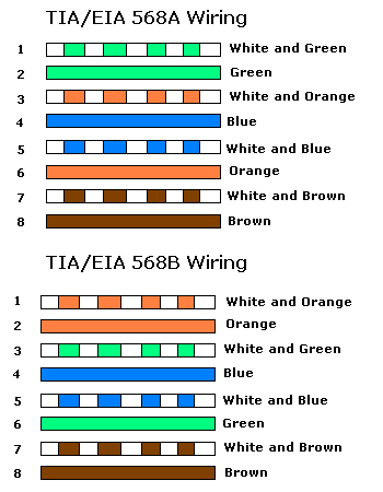
I also need to know the order the wires go into the plugs and the back plates, I've also got some back boxes but the numbers and colours the wires go into are different to another one I had, they are both Cat5e so I'm wondering why they are different, the one on the left are the ones I'm using:

Any help would be mucho appreciated
I'm just not quite sure on how to do it, a friend has loaned me some tools from his work but he doesn't actually do the manual work so wasn't exactly sure how to do it, here's what tools I've got:

I also need to know the order the wires go into the plugs and the back plates, I've also got some back boxes but the numbers and colours the wires go into are different to another one I had, they are both Cat5e so I'm wondering why they are different, the one on the left are the ones I'm using:

Any help would be mucho appreciated


