Big.Wayne said:
I can look up the specifications on any hard-drive and clearly read in plain english what the safe 'operating' temperature is . . . if I go below or above this limit I would expect to have problems, but when it comes to the processor it all becomes a bit 'mysterious'.
Its because the terminology is common to all IC devices, you're catching a glimpse of a whole industry. Primarily, its gives the information designers need to create cooling solutions. The most important one (other than TDP) is the Tc or case temp. Its limit is Tcmax or tcasemax or max working. First thing to know is a "case" is the package, the encapsulation of the device, the body. Intels Tcmax is measured at the external centre of the IHS, the sensor read by the motherboard approximates this value, sort of. The "junction" is the silicon, the core or die. The die temperature is Tj, with a limit Tjmax, Tjunctionmax. Some of the Intel papers specify Tj, some don't. Last time I looked dual core was 85C and quads 100C. The cpu is supposed to throttle near Tjmax, they call it TCC (thermal control circuit) activation, assuming its not disabled. The main worry is if case temps should reached 80C, mainly because the Indium alloy solder starts to melt around that figure.

If you look over the XS threads on the subject you'll see I had a few questions on values for early versions of Coretemp, ver 0.95 is correct afaik. But basically the program reads Hex for an assumed Tjunction and DTS values directly from MSR's, registers on the CPU. DTS (digital thermal sensor) is the 'on' die sensors, not at the hottest points, but that doesn't matter. The Tjunction value is a generic value for the processor type. The DTS creates a value and is calculated thus:
Core Temperature = Tjunction - DTS
So if Tjunction = 85 and the DTS reads 50
Core Temperature = 85 - 50 = 35C
http://www.hardforum.com/showthread.php?t=1192840
http://www.relex.com/resources/art/art_heatsinks.asp
http://download.intel.com/design/processor/designex/31559402.pdf
Take a look through the links. The Intel docs, section 4.2 refers to two signals, THERMTRIP# which can't be switched off or ignored and is likely set to or above Tjmax, supposedly stops any real damage and shuts down. The other is the throttling PROCHOT# value, which can be disabled. Part of the TCC with (its been a while so read it yourself) two functions TM1 & TM2. Basically two types of throttle. Anyway, when the DTS (-ve) tends towards zero the TCC trip limit activates the throttle.
I can't be asked to read the sheets again, but the trip point for the TCC is going to be a bit below Tjmax, which is pointless if you've turned it off anyway. If deactivated it will run higher until it shuts itself down. Best not to go too high just in case Tc gets near 80C and the solder melts.
One of the fundamental problems with thinking you know exact temperature figures for these chips is the DTS does not report absolute values. Only the difference from the preset throttling point, which of course they neglect to tell you where it is for each chip. Albeit very accurate for changes (delta) at higher throttling temperatures, trouble is programs like TAT etc, have to assume a temperature to subtract the DTS from, if that's the wrong one then so is the absolute value.
In the end, the only value Intel expects you to care about (by you I mean users, Engineers etc) are the case temps, Tc. Via the thermal diode, uncalibrated and prone to bios offsets. The throttling is all handled by the chip, along with factory preset thermal trip points. The DTS registers weren't meant to be accessed directly. Due to them giving no indication of the TCC value, then using Tjmax is I suppose a reasonable guess point. Assuming its being read correctly, be warned.
Some speculation for you. You could monitor TAT for thermal activation to determine the TCC, then calibrate offsets in Speedfan to give an absolute value, something like 3C from Tjmax would be my guess. Or and this is what I recommend,
recalibrate your thinking. It doesn't matter what the core temp is as long as its stable and reasonably lower than the throttling point to avoid long term damage. Because it's 100% accurate close to the throttling point, learn to read the direct DTS temperature as a count down. Overclocked, at some point for each chip as the DTS decreases the chip will become unstable. Personally I'd find that point (within a range) and add 10C (your choice) as a safety margin. Say it has problems at DTS=13 (weakest core), then stay above 23. On my dual core that would read as 85-23=62C, remember as I said 62C is not a "real" figure in either Coretemp or TAT. Anyone that's says there is a "norm" for each model of chip doesn't understand how it works.
"The Coolest" has added this feature to the latest 0.95 Coretemp.

Btw, even that is slightly wrong, its the delta to TCC activation.
Some further reading on throttling and accuracy.
http://www.xtremesystems.org/forums/showthread.php?t=131008
http://www.xtremesystems.org/forums/showthread.php?t=136804
http://www.intel.com/design/processor/manuals/253668.pdf
http://www.xtremesystems.org/forums/showthread.php?t=154909
---------------------------------------------------------
For reference: I've posted this derivation before, it get used a lot but no one ever gives the proofs. Its a simplification as I've only considered dynamic power and ignored static wattage. Nor does it consider frequency domains. Static basically means the leakage, the power used at stock voltage with no load. In reality its superimposed and increases with the frequency/voltage curves. But it works well enough in this application.
A commonly used expression is for semiconductor power P, P=kLV²F
Where:
L = Load (from software)
V = Core voltage
F = Chip frequency
k = Empirical constant for the chip.
Pd = Total cpu power
TDP = Thermal Design Power
Therefore delta P, i.e. change in power. The constants cancel.
Pd = TDP x (F2/F1) x (V2/V1)²
Or a little easier to understand
OCed Watts = TDP x (OCed Mhz / Default Mhz) x (OCed Vcore / Default Vcore)²
online version
For temps
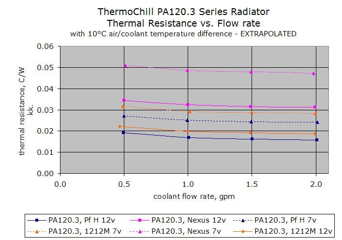
TR = RCS + RSA = (Tc - Ta)/Pd
Where:
TR = Total Thermal Resistance
Tc = Tcase, cpu case temperature
Ta = Chassis ambient temperature
Pd = Total cpu power dissipation
RCS = Thermal resistance, case-to-sink
RSA = Thermal resistance, sink-to-ambient
Therefore:
Tc = (TR x Pd) + Ta
Intel version
---------------------------------------------------------
I'll add an example for those interested is back to basics thermal resistance.
Arctic Silver Thermal Resistance:
0.0045°C-in²/Watt (0.001 inch layer)
Assumed 1in²/ contact area on IHS.
Tuniq Tower 120 Thermal Resistance:
0.16-0.21 C/W (2000 - 1000 RPM)
Using (
Intel version):
TR = 0.16 + 0.0045 = 0.1645 C/W (Tuniq at 2000RPm with AS5)
Ta = 25C (thermometer inside case)
Pd = 65W (stock settings as
Intel TDP ref, 2.4GHz 1.325v, they all say 65W which they can't be, but that's all there is to go on)
0.1645 = (Tc - 25)/65 Therefore Tc = 35.7C

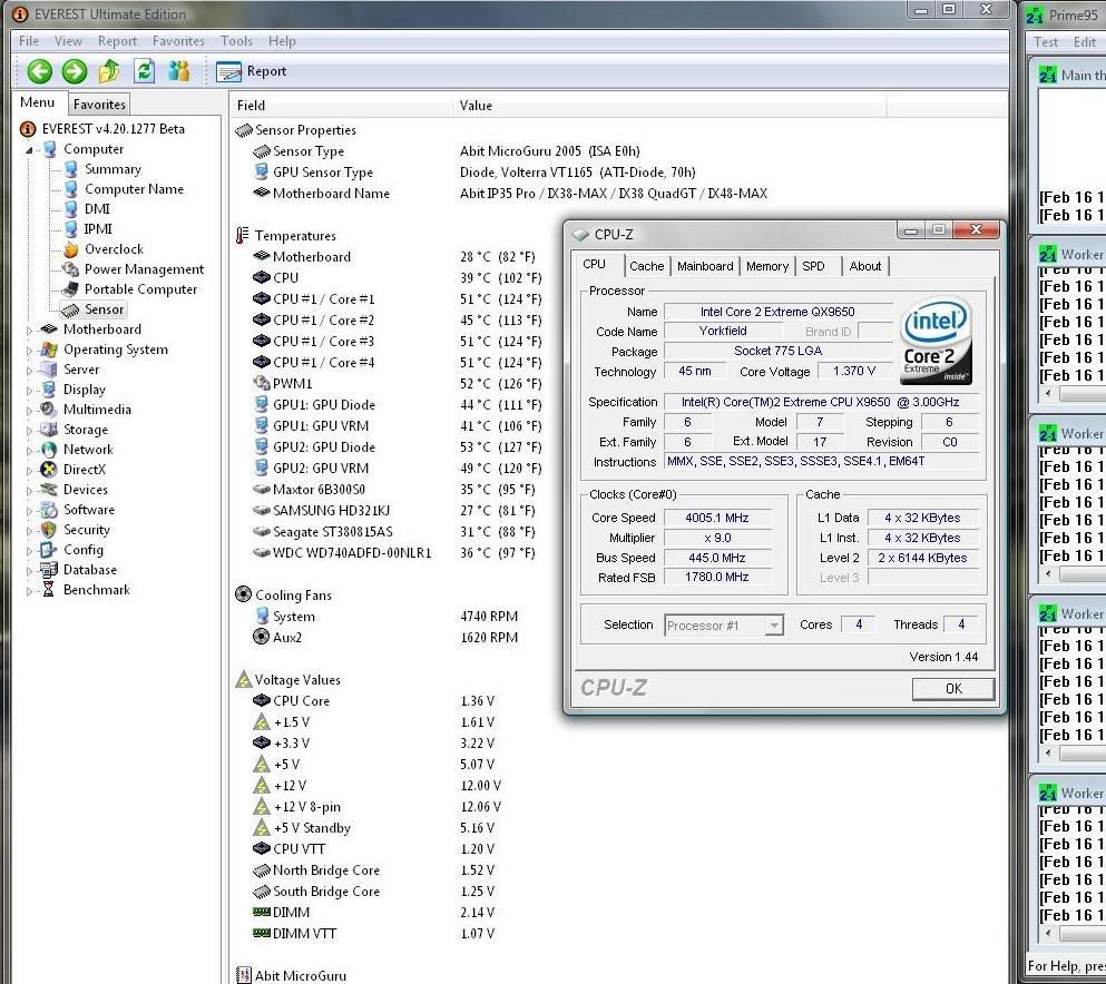
An independent way of estimating the temperature the HSF is actually seeing and proves close to the speedfan/ProbeII values of 34C. If the cpu were at 44C, then at stock speeds and voltages the power dissipation would be Pd = 115W, way more than the stock 65w max thermal design profile.
Going to the other extreme
[email protected]
Pd = 65*(3600/2400)*(1.5/1.325)² = 125W
Therefore Tc = 45.5C

Again very close to the speedfan/ProbeII 46C!!!
------------------------------------------------


")
 , same as Quads !!

 There's a certain degree of truth to that, as some people place them in the oven to melt the solder off to remove the IHS and is presumably the reason why it's 85C as if this temperature is exceed the solder will melt (can't remember the exact figure but it's less than 100C). There could be certain instances, especially in hot sunny countries where you could possible exceed that figure when the CPUs are in containers left out in the sun. For example, as part of my job, for desert installations it's not unheard of to provide sunshades for instrumentation located in the sun to prevent them overheating (though there is the added hazard that hot surfaces >60C can be an ignition source during gas releases
  )
)