

I could do with a little tech advice re wiring in the LED toggle switches I have. I built a switch box a while back using toggle switches with blue LEDs in the ends which lit up when you turned the switch on these were fairly easy to sus re what went into what re -ve and +ve etc
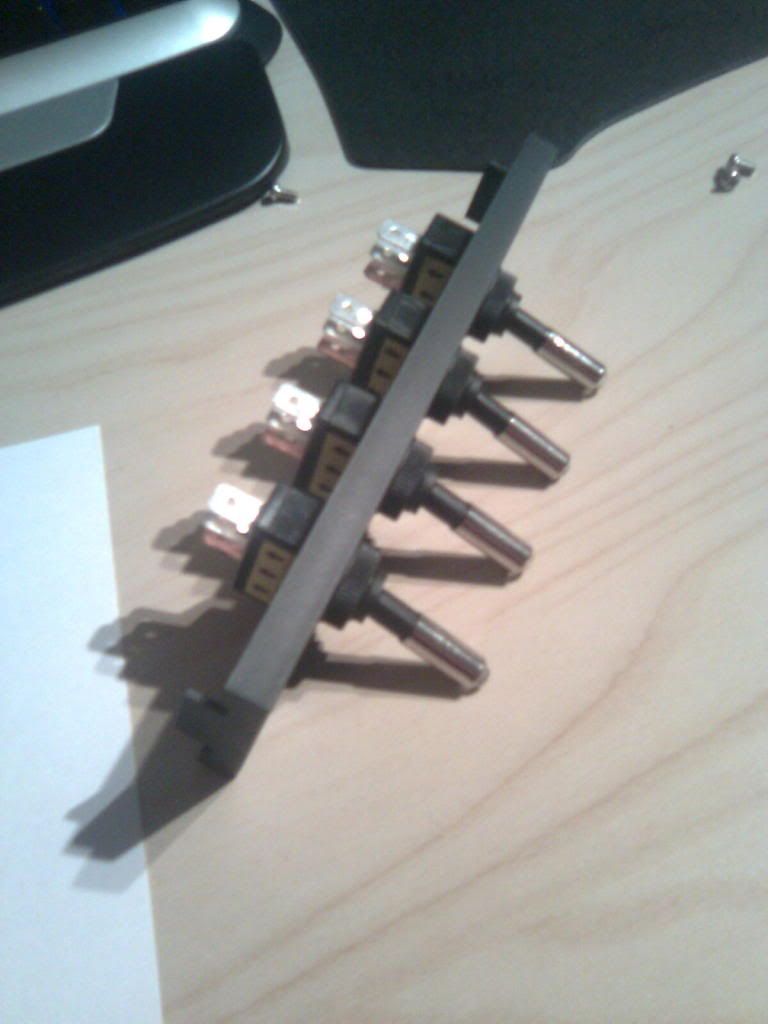
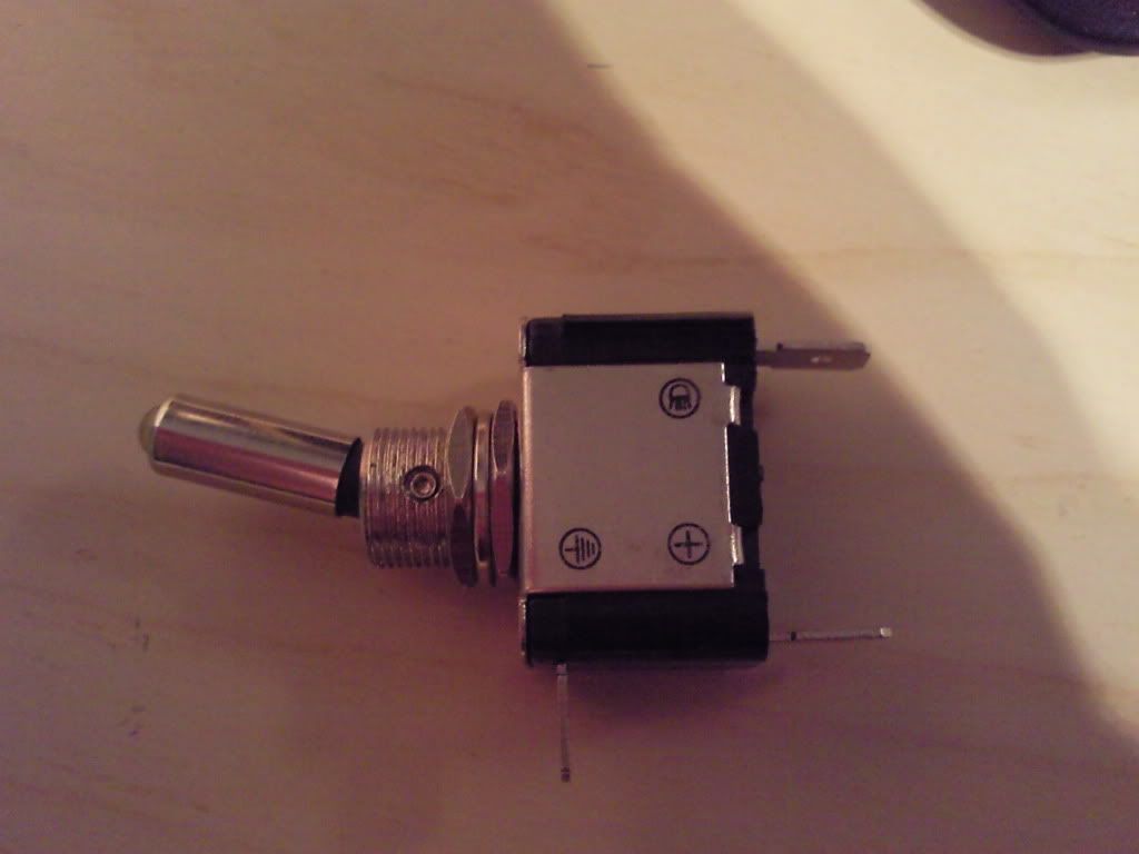
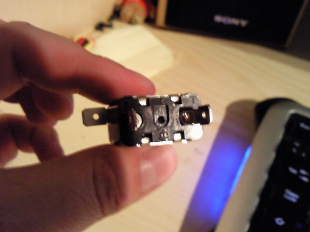
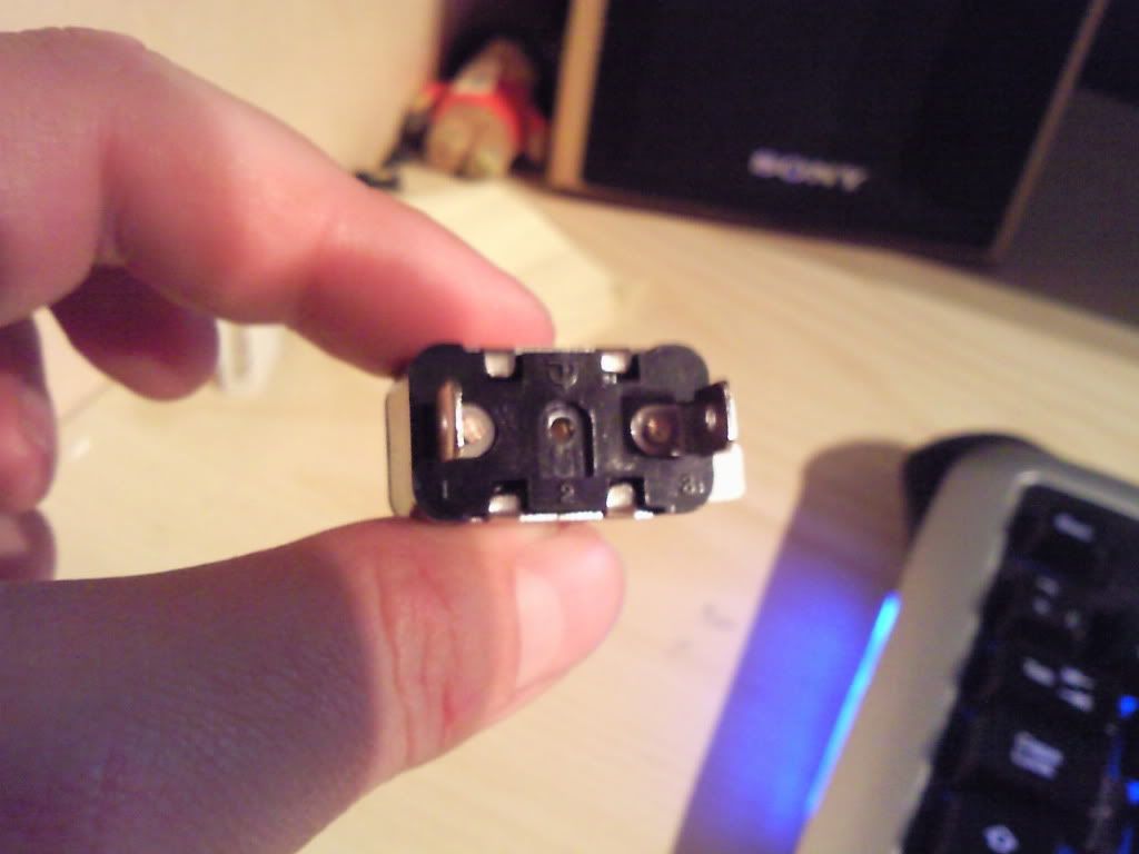
In line with my new build I have purchased some with yellow LEDs in the ends, however the terminal layout is not quite so obvious, and annoyinly have one of the terminals coming off the bottom of the unit. It has the earth symbol on it, so is that -ve in a PC case? also, there is a what looks like a screw hole between the other two terminals marked with the same symbol so I might be able to use that instead saving me having to try to bend the other terminal round to make it fit.
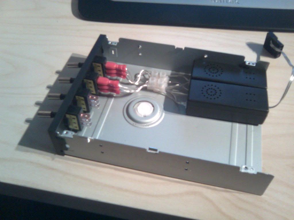
If anyone would be kind enough to show me how to wire these in, the feed will be from molex off the PSU, and the output will need to go into a CCFL inverter as per the current set up
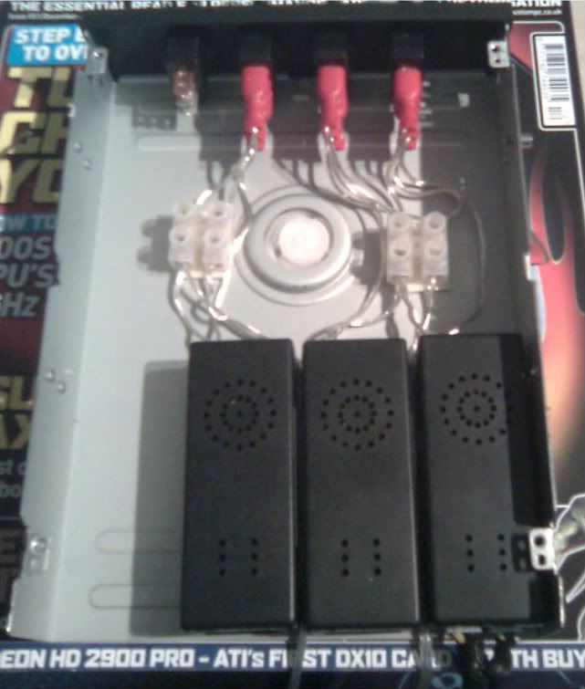
Pictures of how the existing switches are wired in, and the new switches for comparison.
In line with my new build I have purchased some with yellow LEDs in the ends, however the terminal layout is not quite so obvious, and annoyinly have one of the terminals coming off the bottom of the unit. It has the earth symbol on it, so is that -ve in a PC case? also, there is a what looks like a screw hole between the other two terminals marked with the same symbol so I might be able to use that instead saving me having to try to bend the other terminal round to make it fit.
If anyone would be kind enough to show me how to wire these in, the feed will be from molex off the PSU, and the output will need to go into a CCFL inverter as per the current set up
Pictures of how the existing switches are wired in, and the new switches for comparison.