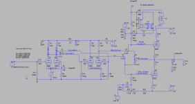
Not built but currently in the design stage - a valve headphone amp.
The phones I'm targeting are being able to support a 32ohm impedence headphone rather than the normal 600ohm that tube users use. The unofficial industry standard seems to be settling on 120ohms - the phones I have are 55ohm AKG420mk2s.
Low impedances use lower voltages (smaller voltage swings peak-to-peak) and higher current with solid state amplification it's easier to run more current than attempt to support higher voltage. This is the reason there is a trend to low impedance with iPod etc.. This also means the headphone coils are heavier to cope with the current (a larger cross section needed to prevent heating up).
High impedance use higher voltage (larger voltage swings peak-to-peak) and small current. These originally appeared as valves (tubes) can support big voltages but can't really supply current. Hence the headphones with high impedance are made up of thinner coils as less current is used.
First thing todo is to understand the headphones - 55ohm stated, in fact this impedance depends on the frequency, and the phones actually measure between 55 and 200 with a 84ohm average. However you need to support the lowest impedance. These are for each headphone channel, these values are all 104dB/Vrms sensitivity targeting 110dB max:
32ohm = 2Vrms drawing 62.5mA so 125mW of power.
55ohm = 2Vrms, 36mA so 73mW
84ohm = 2Vrms, 24mA so 48mW
200ohm = 2Vrms, 10mA so 20mW
Note the rms value - 2Vrms is 5V peak to peak (ie +2.5V to -2.5V). Also the fun that is milli-amps (or 1mA=0.001A). The valves I'm using - the pre-amp only outputs 10mA max and the output tube delivers 110mA max in an amplifier situation. This is why you'll see a lot of valve amps with a MOSFET output to deliver current.
The next bit is that valves' input needs to be in a certain range - to be amplified to the right level. That amplification factor means you need a couple of stages to boost the voltages. The input of a valve is all about voltage and not current.
So you end up with a chain that needs to be designed. However the characteristics of a valve aren't entirely linear, and have a number of variables - plate voltage (the voltage applied across the valve), grid voltage (this is a negative voltage to the cathode that controls the valve) and the cathode (which provides the electrons)
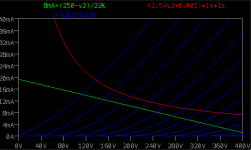
I won't get into the workings of all the different types of valves but for the ones I'm thinking of using - triodes - these work by applying high voltage across the cathode and plate, in the region of 100-300V, then supplying a signal (+/- voltage wave) to the gid. In reality there are a couple of addition points:
* current bias - for constant current flow (CCS) is an improvement over standard simple valve setups to reduce distortion.
* tube bias - this is the negative voltage that carries the signal to control the valve. The more negative the more the valve is shut off - with 0V being no control and normally a bad thing.
So working back from the headphones - I need to look at valve data sheets and understand the the characteristics to get a minimum distortion, ensure we get low harmonics that are even rather than odd plus sit in a range of being the most linear. The subject for the next post.


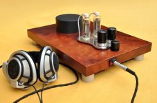
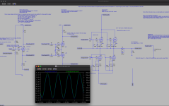
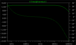
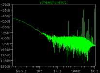
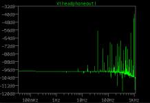
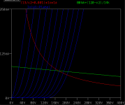
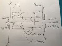
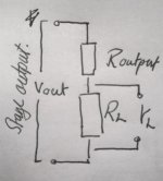
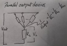
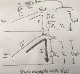
 (remember our triode valves max out at 120mA each in class A!).