Onboard vs Sound Card

Soldato
Joined
19 Jun 2009
Posts
3,874
i have the essence card too and love it. paired up with focal xs speakers it gives lovely sound.

Totally agree it's a very good sound card indeed, I actually own 2 of them. My Pioneer AMP/DAC still has less interference/background noise then both my Essence ST's however. Nothing wrong with the Asus Essence ST and it will still outclass most consumer sound cards, however I prefer to use my Pioneer AMP/DAC over it. This is on my HiFi setup mentioned above, on my software dev rig I still run one of the Asus ST's.

PS the reason I own 2 Asus Essence ST's is I planned on using one also on my HTPC/Hi-Fi setup, I spent days listening, sleeping in between, listening to different music at 3am in morning, but the Pioneer AMP/DAC won over it, but close enough it took a few days to decide.

I also own a Creative Titanium HD and in comparison to above, it took only 10-15 mins for me to realise the Asus ST was better then the Creative Titanium HD, the quality between the Asus and Creative makes it easy to decide the Asus is better. The main difference between the Creative and Asus is the Creative sounds slightly synthetic, where as the Asus ST has a more honest analogue sound.
 
Last edited:

V F

V F

Soldato
Joined
13 Aug 2003
Posts
21,184
Location
UK
Totally agree it's a very good sound card indeed, I actually own 2 of them. My Pioneer AMP/DAC still has less interference/background noise then both my Essence ST's however. Nothing wrong with the Asus Essence ST and it will still outclass most consumer sound cards, however I prefer to use my Pioneer AMP/DAC over it. This is on my HiFi setup mentioned above, on my software dev rig I still run one of the Asus ST's.

PS the reason I own 2 Asus Essence ST's is I planned on using one also on my HTPC/Hi-Fi setup, I spent days listening, sleeping in between, listening to different music at 3am in morning, but the Pioneer AMP/DAC won over it, but close enough it took a few days to decide.

I also own a Creative Titanium HD and in comparison to above, it took only 10-15 mins for me to realise the Asus ST was better then the Creative Titanium HD, the quality between the Asus and Creative makes it easy to decide the Asus is better. The main difference between the Creative and Asus is the Creative sounds slightly synthetic, where as the Asus ST has a more honest analogue sound.

Hmm, I wonder if I should go for the Asus STX II to upgrade from the Auzentech X-Fi Prelude. So many spoke many years ago the Prelude was as good if not better than the Titanium HD.

Yet some people say the AE-5 is better than Asus cards. :confused:
 
Soldato
Joined
19 Jun 2009
Posts
3,874
Hmm, I wonder if I should go for the Asus STX II to upgrade from the Auzentech X-Fi Prelude. So many spoke many years ago the Prelude was as good if not better than the Titanium HD.

I can only comment about the cards I've owned, never heard any of the newer Creative cards so no idea how they sound. I think the Creative Titanium HD is a really good card, it's better better then the Creative Xtreme Music I use to own many years ago. However on the Creative cards I've owned I get the feeling there a bit synthetic, where as the Asus ST is more like a good quality CD player that's honest and does 2.0 and nothing else.

It falls down to this. If I was building a dedicated gaming rig I would install the Creative Titanium HD as it has EAX. However if 2.0 music was the priority then the Asus ST is the better card, main reason is sound is more honest, feels like it's less interfered with.

Changing cards also comes down to amp / speakers. If you have £100 worth of active speakers it's probably not worth you changing source, however if you have £500+ of amp / speakers then worth considering changing cards.

Yet some people say the AE-5 is better than Asus cards. :confused:

You have to listen to people that have owned both the Asus Essence and the AE-5 together to get a fair review. For a perfect comparison you need both cards installed at once, then play the same music switching between them. The problem with the internet it's knowing who to trust.
 
Associate
Joined
3 May 2018
Posts
604
If you are picking up EMI/RF noise from the PC, very often the GPU/display output/hdmi switching, then a PCI(e) sound card may not help. A lot of that comes down to motherboard PCB layout and component shielding. There is a chance the PCI sound card will improve things, but there is a chance it will not.

In analogue electronics digital signals are a curse as they often switch fairly high current in large voltage swings causing ground plane and signal EMI/RF to surrounding electronics. Sound has to be DAC'ed and then amplified as analogue signals along with any noise.

A better (more expensive) mother board is usually better thought out, uses better layout and components to reduce digital switching noise. Making sure your audio cables are not routed past noisy digital electronics can help, but if your motherboard (and PSU) are noisy then nothing inside the case is going to help.

An external USB sound card will eliminate virtually all that noise, though some can still be transferred on the USB ground and power lines and a cheap USB headset can then amplify that into the speakers.

You DO NOT need to go for a boutique, audiophool style 192Khz DAC, a basic 48Khz stereo DAC is still fine for 99% of uses, unless you want to run a surround system.

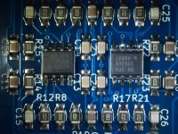
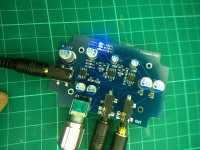
I built my own from a PCM2904 DAC. It was implemented with a power filter and low noise voltage regulator as per Texas Instruments datasheet and is silent regarding noise pick up.

I recently got a top of the line Asus Crosshar VII board and suprisingly it's audio output is fairly clean, only a tiny bit of pick up at full volume. But it has a very carefully laid out sound region on the board including EMI shielding, physical cuts through the board and guard traces/planes. Still there is noise at full volume if you listen for it. So an absolutely no, no for any studio work. It does support 192Khz audio, but I left it at the default 48Khz as I have no use for ultrasonics.
 
Man of Honour
Joined
13 Oct 2006
Posts
91,147
I built my own from a PCM2904 DAC. It was implemented with a power filter and low noise voltage regulator as per Texas Instruments datasheet and is silent regarding noise pick up.

Built a couple using the PCM2902 (with the additional regulator - used a LP2951 - for analogue and a load of other power management/filtering changes) they aren't bad but TBH the sound quality isn't in the same league as something like the ESS Sabre, etc. I've been looking for a good USB<>I2S bridge or similar to try the PCM179x range, etc. but it isn't a very DIY friendly area (CP2114 would have been ideal if they'd made it in something other than QFN) - could use the digital output on the PCM270x series but that has limitations of its own :( (Even on prototype board though very very little noise (essentially silent unless you scope it) with reasonable grounding and good filtering of inputs signal and power).
PC Audio annoys the **** out of me as often filtering (or resilience by layout) stuff like digital switching noise is relatively easy as it is mostly >100KHz and fairly consistent unlike some other types of noise/interference but often even lacking the simplest of filtering on consumer devices and often just a little more spent on capacitors, etc. even though its a "5%" difference just produces an overall more pleasing result.
 
Associate
Joined
3 May 2018
Posts
604
Yes the TI PCMs are built for "Desktop/Consumer audio". I find the sound quality perfectly acceptable for my setup. I did implement a TI reference design for the output filter using high end OPAs.

The split DAC approach is useful if you really need to separate the USB power rail noise out of the analogue side of things. You can even go as far as using a high speed opti-isolator for the digital signal to completely separate from the USB.

I wouldn't worry took much about TQFN packages though, get yourself a hot air rework gun like the 898D and some solder paste and you can solder anything!

It's one thing about building stuff yourself, you can build to a spec and not a price. Using things like low ESR aluminium polymer caps and XR7's SMD caps doesn't hurt for small runs, but stings for large production, so in commercial gear the bean counters usually downgrade everything the engineers will allow them to to the cheapest they can find. I believe it makes a difference.

I made my DAC schematic and PCB public you can find the link here: http://www.eevblog.com/forum/beginners/audio-dac-output-low-pass-filter/msg1465385/#msg1465385


e54ebij.jpg

It is complimented with this little beast.... two OPA551 2 watt output headphone amplifier. If you think 2 watts is excessive consider winding up the bass frequencies usually pulls significant power.
Azahrdd.jpg
 
Man of Honour
Joined
13 Oct 2006
Posts
91,147
get yourself a hot air rework gun like the 898D and some solder paste and you can solder anything!

Hah was going to mention that I'd been thinking about it - I've got some OPA1692 to play with that are VSSOP - I can do down to SOIC easy and SSOP with a bit of patience but not sure I have the patience for doing small packages that use VSSOP with a regular iron.

The split DAC approach is useful if you really need to separate the USB power rail noise out of the analogue side of things. You can even go as far as using a high speed opti-isolator for the digital signal to completely separate from the USB.

I've made liberal use of DC-DC POL devices such as the DCP0105 series - sure they are switching but very easy to filter and provide great isolation from ground conditions and other noise - usually cap bank and then regulators such as LM317.

It is complimented with this little beast.... two OPA551 2 watt output headphone amplifier. If you think 2 watts is excessive consider winding up the bass frequencies usually pulls significant power.

IIRC they can be a little scary with regard to output shorts - fortunately I've not really had much need for that kind of power.
 
Last edited:
Associate
Joined
3 May 2018
Posts
604
IIRC they can be a little scary with regard to output shorts - fortunately I've not really had much need for that kind of power.

They are output short circuit protected for constant short circuit. However, when shorted they can put out 200mA each. My headphone amp has 33 Ohm current limiters on the output and a 16V limit, so after taking the rail losses off the amp, call that +6V / -6V through 33Ohms is a max current of 6/33 = 181mA. Importantly, 6^2 / 33 = 1.09 Watts (per channel) and not really enough to melt headphone cables. This is in addition to the 36 Ohms provided by my headphones. So even though the amps can put out over 1 watt per channel, my implementation with my headphones is limited to about 0.6W per channel.

Of course as it's a self build it would take me all of 5 minutes to remove or reduce the series output resistors.

The amps are also thermal protected and while I implemented the thermal shutdown lights I doubt I will even see them on while driving headphones. If I plug a set of 8 watt 8 Ohm desktop speakers I think I could get them to light.

On needing power. If you connect this amp with my headphones to a bog standard sound source, such as a phone, with no EQ and give it more than 50% volume it will be disturbingly loud and probably cause hearing damage in the mid to long term use.

However, if you put in a bass weighted V on the EQ, you can run about +12db bass bias and the headphones still do not distort. It is a common miss conception that it is the headphones distorting with too much bass when it is usually the amps current limiting. Most "nanny state" headphone amps use standard 10 or 20mA op amps which are speced so that full volume is under about 94db and when boosted in bass distort due to current limit on their outputs getting hit.

My headphones are modest, Audio Technica M50x's.
 
Man of Honour
Joined
13 Oct 2006
Posts
91,147
That is a nice setup. Mostly I just dabble on prototype board but thinking of doing a proper PCB for a "pseudo balanced" type amp I want to do for my HD600s.
 
Man of Honour
Joined
13 Oct 2006
Posts
91,147
I have it roughly laid out in ExpressPCB but their direct production estimates are like $300-600 LOL (it will be a fairly big board).
 
Associate
Joined
3 May 2018
Posts
604
What are you building, why so big? Can you not go surface mount and compress the board down a bit? You could also go darkside and put components on both sides of the board.
 
Man of Honour
Joined
13 Oct 2006
Posts
91,147
What are you building, why so big? Can you not go surface mount and compress the board down a bit? You could also go darkside and put components on both sides of the board.

Essentially a dual-mono headphone amplifier so everything is doubled - plus using some "boutique" film capacitors which tend to be fairly large - also the case is intentionally chosen so the board needs to fit that as well.
 
Associate
Joined
3 May 2018
Posts
604
Film? Why not polymer or tantalum?

Still can't work out how you got it to be $118! Though. Was that "assembled" or just the board?
 
Man of Honour
Joined
13 Oct 2006
Posts
91,147
I use polypropylenes a lot (around opamps in audio use) - just prefer them.

Just the board - it is 16x12cm - I'm using a lot of copper for various reasons some of it heatsinking.
 
Last edited:
Associate
Joined
3 May 2018
Posts
604
So you must be selecting things like gold finish and impedance matching a 160x120 board quotes at $36 on AllPCB. I would recommend building the board with the cheapest option the first time. Adding all the bells and whistles will hurt if you notice an error and need to reprint the board.

Polypropylenes do not appear to be the correct choice for audio, anything other than a small LP filter cap in the pico farad range looks like a dustbin in size! For audio coupling caps you'll want at least 22uF and I prefer 220uF so they don't roll off the low end bass at all. Typically a rubbish bass response from an amp is because they skimped on coupling caps.

I use these:
https://uk.rs-online.com/web/p/aluminium-capacitors/1734816/

They are extremely low effective series resistance and fairly cheap and small.

For anything 10uF and under I use 0805 XR7 surface mounts.
 
Man of Honour
Joined
13 Oct 2006
Posts
91,147
I'm blocking DC at the input (only need ~0.47uF film cap this way) using film caps and using dual out power supplies (negative rail) so I don't have to use an AC coupling capacitor on the output. I'm also using high speed PP 0.1uF caps for decoupling the powersupply, etc. near the opamps and so on.

Its a bit self-indulgent/overkill but I'm just doing it for fun and not particularly worried about trying to be cost effective, etc.

With the design I'm using IIRC I'd need atleast 470uF coupling caps to make sure I wasn't getting any bass roll off - though its a little while since I looked into that aspect of it so 220uF might have been sufficient.
 
Last edited:
Associate
Joined
3 May 2018
Posts
604
It depends on if you have any resistance in parallel or series with the cap. Mine was originally spec'd to have 22uF on the outputs, but as I have a 33Ohm series resistor the Bode plot showed the -3db roll off at about 80Hz, so I upped it to 220uF and I think it was moved to about 40Hz.

DC blocking caps will need to be at least 22uF, but be careful how they then interact with your volume control.

Power decoupling caps for a powerful headphone amp need to be significantly higher than 100nF. While 100nF will filter high frequency noise of you power rail they will provide little charge for instantaneous demand from the amps. Best to check the datasheet for the opamps, they often have a "Typical Application" circuit and information about decoupling. The OPA551s have 10uF and 100nF on both + and - rails.

It is also wise to have a basic power input decoupling cap, something like a 470uF on the input power rail, in addition to the localised opamp decoupling caps.

These provide energy storage for large spikes in current which would otherwise drop the voltage all the way along the wires to the power supply until it can respond properly.

The power decoupling caps do not need to be anything special though.

I recommend downloading LTSpice and reading a tutorial on running Bode plots through it for your circuit. It can alert you to oops in the design that give poor results. If you are using a switch mode supply you might want to consider putting a cap in the feedback path of the op amps to filter out high frequencies, something like a 330p or 100p. LTSpice will let you tune these without all the scary mathematics required.
 
Back
Top Bottom