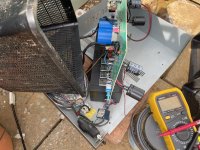
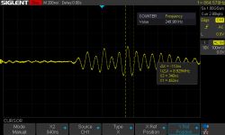
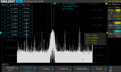
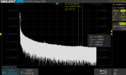
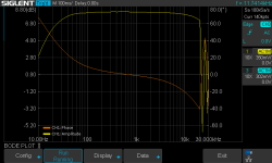
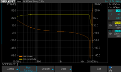
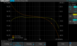
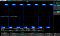
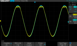
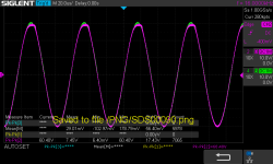
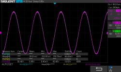
I bought this 24 years ago in 1998 and I thought it was about time I investigated some obvious hot traces for the mute control. I hooked up the scope and switched on good but needed to change the parameters. Switched off and on again and I had a light show. I was half expecting something like this at some point - it's getting old and if it's totally dead I have a nice case and metal hardware to make a brand new tube amp 
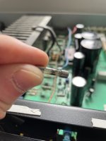
That fuse is rated at 250V T6.3A and the transformer is providing around 30Vac. So quick bit of maths, R=V/I so 30/6.3=4.7ohm, and P=I*I*R = 6.3*6.3*4.7 = 189 watts before that fuse goes pop. The amp has two - one for positive and one for negative rails. So something on the positive rails sucked a lot of power.
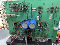
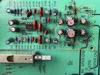
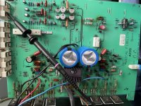
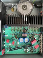
Here's the board being stripped down - can you see the hot spots? (discoloured PCB). The fuse holder at the bottom left side is the one that blew. Above around that are 400V caps, and above that BR1 is the bridge rectifier - a 400V 10A device that converts AC to DC. Looks like it got a bit hot down one side.
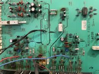
Sure enough a test of the AC to the +Vdc rail portion of the bridge rectifier showed a full short. So no rectification and lots of current flow.. especially when 15000uF + 2x 3300uF 50V caps are connected directly to that along with the rest of the amp. So the fuse and bridge rectifier need replacing - easy.. but what caused the over current condition?
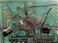
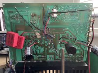
The amp is simple - power comes in, goes to the power transistors attached to the big black heatsink at the bottom of the picture - 2 for left and 2 for right for the positive and the same for the negative rail. Well the speakers are still work fine, so after desoldering the n-channel positive side mosfets - these test ok. They should do - they can cope with 8A at 160V each. Phew - these are obsolete and have no replacement and even the substitutable pieces need some playing to get to work.. So what else?
The amp is packed with electrolytic caps - all rated at 85degC. This amp is class AB and is biased so hot that you can't keep your hand on the top of the case. That's on the outside.. the inside of the amp turns into an oven.. 24 years of cooking and they are prime suspect. Even when they test at 9-24Mohm it's unlikely they're still good.. well they do hold charge but given they just got connected in reverse thanks to the BR failure.. that's likely to cause a massive current flow.
Option two for failure is that the amp went into oscillation at a high frequency but we've already tested the output mosfets and they're ok.
I've since tested the transistors in the driver section, the mute etc by desoldering them and testing them - all ok. Given nothing else in there is really voltage or polarity sensitive.. that leaves the caps and the old bridge rectifier as being the main actors in this. There doesn't seem to be any further burning of the PCB. After investigating the mosfet bottom right second in that is current removed, that tests ok but there was no real thermal connection to the heatsink! That would explain the rather toasting via the heat going down the legs and burning the PCB.
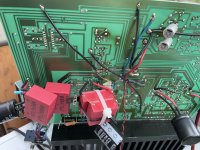
I've also noted some rather dumb parts of the design - first the signal goes through an electrolytic cap rather than a film cap hence you get less detail and the cap acts like a filter, so I have a couple of 0.22uF film caps I can use to test out any improvement (WIMA FKP1, WIMA MKP series 1uF and a Panasonic MPP 0.22uF) that I will try once it's back running. Also the designers use polystyrene caps which if you know about them.. they change with temperature and once change stay like that forever.. a bit crazy and unpredictable given the oven heat of the amp during operation.
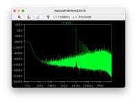
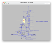
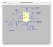
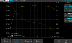
I've ordered new caps, a new bridge rectifier, fuses, some thermal pads, and two 100W 8ohm resistors to act like speakers for testing. I've also been modelling the amp in a simulator and there's some additional stability mods to remove some 2MHz noise that causes problems with the amp and I can make that may help make the amp sound better too. Just need to order some more caps.
I'll start the amp with a light bulb in the power line - this sounds odd but limits the current that the amp can draw from the mains. I can then essentially power up the amp but limit the current being drawn through it so if something is going pear shaped then I can see it in slow motion and stop it before it goes bang.


That fuse is rated at 250V T6.3A and the transformer is providing around 30Vac. So quick bit of maths, R=V/I so 30/6.3=4.7ohm, and P=I*I*R = 6.3*6.3*4.7 = 189 watts before that fuse goes pop. The amp has two - one for positive and one for negative rails. So something on the positive rails sucked a lot of power.
Here's the board being stripped down - can you see the hot spots? (discoloured PCB). The fuse holder at the bottom left side is the one that blew. Above around that are 400V caps, and above that BR1 is the bridge rectifier - a 400V 10A device that converts AC to DC. Looks like it got a bit hot down one side.

Sure enough a test of the AC to the +Vdc rail portion of the bridge rectifier showed a full short. So no rectification and lots of current flow.. especially when 15000uF + 2x 3300uF 50V caps are connected directly to that along with the rest of the amp. So the fuse and bridge rectifier need replacing - easy.. but what caused the over current condition?
The amp is simple - power comes in, goes to the power transistors attached to the big black heatsink at the bottom of the picture - 2 for left and 2 for right for the positive and the same for the negative rail. Well the speakers are still work fine, so after desoldering the n-channel positive side mosfets - these test ok. They should do - they can cope with 8A at 160V each. Phew - these are obsolete and have no replacement and even the substitutable pieces need some playing to get to work.. So what else?
The amp is packed with electrolytic caps - all rated at 85degC. This amp is class AB and is biased so hot that you can't keep your hand on the top of the case. That's on the outside.. the inside of the amp turns into an oven.. 24 years of cooking and they are prime suspect. Even when they test at 9-24Mohm it's unlikely they're still good.. well they do hold charge but given they just got connected in reverse thanks to the BR failure.. that's likely to cause a massive current flow.
Option two for failure is that the amp went into oscillation at a high frequency but we've already tested the output mosfets and they're ok.
I've since tested the transistors in the driver section, the mute etc by desoldering them and testing them - all ok. Given nothing else in there is really voltage or polarity sensitive.. that leaves the caps and the old bridge rectifier as being the main actors in this. There doesn't seem to be any further burning of the PCB. After investigating the mosfet bottom right second in that is current removed, that tests ok but there was no real thermal connection to the heatsink! That would explain the rather toasting via the heat going down the legs and burning the PCB.
I've also noted some rather dumb parts of the design - first the signal goes through an electrolytic cap rather than a film cap hence you get less detail and the cap acts like a filter, so I have a couple of 0.22uF film caps I can use to test out any improvement (WIMA FKP1, WIMA MKP series 1uF and a Panasonic MPP 0.22uF) that I will try once it's back running. Also the designers use polystyrene caps which if you know about them.. they change with temperature and once change stay like that forever.. a bit crazy and unpredictable given the oven heat of the amp during operation.
I've ordered new caps, a new bridge rectifier, fuses, some thermal pads, and two 100W 8ohm resistors to act like speakers for testing. I've also been modelling the amp in a simulator and there's some additional stability mods to remove some 2MHz noise that causes problems with the amp and I can make that may help make the amp sound better too. Just need to order some more caps.
I'll start the amp with a light bulb in the power line - this sounds odd but limits the current that the amp can draw from the mains. I can then essentially power up the amp but limit the current being drawn through it so if something is going pear shaped then I can see it in slow motion and stop it before it goes bang.


