short circuit advice on asrock Z77E-ITX board

Associate
Joined
31 Jan 2022
Posts
7
Location
uk
hey there, i was after some help, if anyone can offer.

im trying to get a z77e-itx motherboard working, that has no power.

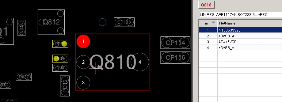
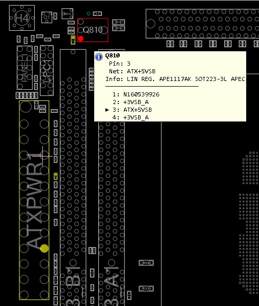
im pretty sure it has a short, because as soon as you flick the psu on, a mosfet on the board, not far from the 24 pin connector, gets red hot, straight away.

i dont want to leave the psu switched on, for anymore than a few seconds, as it might kill the mosfet ?

what do you guys recommend doing ?

could that mosfet be causing the problems ?
should i remove it, and try connecting the psu again ?

also, there is a few smd capacitors, or resistors, that have been somehow knocked off the rear of the board, by the previous owner, and i need to get my hands on a schematic diagram, to figure out what components need to go in those places.

anywhere i can find that schematic file ? ive scanned google for a couple hours, but no joy, not sure where to look for such things.

any help, much appreciated.
 
update - i found a schematic.
had to pay for it, but dont think there was much choice.
hopefully will shed some light on the matter.

this pin on the mosfet, highlighted red, is the only 1 of the 4 pins, thats connected directly to the 24 pin power feed, so im assuming voltage is getting to there, and then short circuiting somehow.

z77e-itx.jpg
 
If it glows red, it's already goner.
Semiconductors simply don't tolerate such temperatures.
Really no electronics component can take red hot temperatures.

And basing on schematics it's not any MOSFET, but linear regulator fed by 5V standby.
https://www.tme.eu/Document/ca15ddc51671592de3c8a08339c1f5ee/APE1117A-3.pdf
It should also include thermal shutdown, so it's obviously badly broken.

With its position under PCIe slot lock mechanism and next to DIMM slots getting it replaced wouldn't be the easiest job.
https://www.asrock.com/mb/photo/Z77E-ITX(L2).png
Also its failure might have been caused by something drawing too nuch current for longer duration with high ambient temperature.
(that's where most graphics card dump their heat)
 
Definitely won't ever work with MOSFET there...

I did read your post after :cry: My bad I just assumed the op had already identified it as a mosfet :)

That wont be easy to replace though and you probably going to have to heat the board from underneath like you do for plastic connectors... you better hope that the chip hasn't fused itself to the ground plane or something :D chips that get super hot like that always tend to fuse themselves to something.

I haven't done a PC motherboard yet but I have one in my "stuff to fix" pile. If this was a switch board I may be more use :cry:
 
Last edited:
If it glows red, it's already goner.
Semiconductors simply don't tolerate such temperatures.
Really no electronics component can take red hot temperatures.

And basing on schematics it's not any MOSFET, but linear regulator fed by 5V standby.
https://www.tme.eu/Document/ca15ddc51671592de3c8a08339c1f5ee/APE1117A-3.pdf
It should also include thermal shutdown, so it's obviously badly broken.

With its position under PCIe slot lock mechanism and next to DIMM slots getting it replaced wouldn't be the easiest job.
https://www.asrock.com/mb/photo/Z77E-ITX(L2).png
Also its failure might have been caused by something drawing too nuch current for longer duration with high ambient temperature.
(that's where most graphics card dump their heat)

i mean, it wasnt glowing red, about to start a fire hot.... but with my finger on it, and then switching the psu on, it would burn me within a second or 2, so its getting heated pretty high, very rapidly.

its a voltage regulator is it... ok, youll have to excuse me with names, i know literally nothing about electronic components, it looked similar to a mosfet, so i just guessed thats what it was.

yeah, that component is tucked away, right under the edge of the pci hold down.... to be honest, i will probably cut that that plastic tab off, to get better access to it. its not needed to make it work, and the board is currently dead anyhow, so i have nothing to lose.

so i guess the next step would be to get the soldering iron out, and pull that 'voltage regulator' off.
ill have to google how to test one, after its off, see if its shorted or not.
 
so i guess the next step would be to get the soldering iron out, and pull that 'voltage regulator' off.
You basically need SMD/hot air rework station.
Normal soldering iron doesn't really work for anything but the simplest SMD components.
 
i did a bunch of continuity tests on that voltage regulator, the connections into it, across it, and out of it, and everything that it links to, seems to be ok, as far as the motherboard schematic displays.
each of the pins connect to the components there supposed to, and none of the regulator pins are shorted against each, apart from the 2 outputs.

as far as i can tell, that chip is not supposed to have a ground connection either. i checked all 4 pins, nothing linked to ground.

i also read somewhere, that those variable regulators do get hot, as they dump excess voltage out in heat form, during the conversion process.
this one converts 5v to 3.3v, but to get that hot, that fast, isnt normal surely ?

hmmm. maybe that part is ok, and the problem is elsewhere. i dunno.

there are several of those minute smd capacitors (or resistors) im not sure, in other sections of the board, here and there, that beep on the continuity test.
short somewhere, linking 2 circuits together, if i had to guess.

im confused.
i need a microscope really, to check the board for damage. theres a couple scratches on it down to the copper, and 5 caps/resistors that have been knocked off.
a few areas of general damage, that are suspect.

what does ' N160539926 ' mean on pin 1, i dont understand.
that pin goes to a resistor, and the resistor goes to ground.

z77e-itx-2.jpg
 
Last edited:
Before I start, I would say ITX motherboard is usually too densely packed with components and likely 6 layer pcb, unless it is obvious it is usually not worth the trouble.

here is how I would diagnose, first I would use thermal scope to look for hot spots, or use the ethanol evaporate method without thermal scope. Which you have done.

I would then desolder the offending part and test it independently, no point in testing while on board, I would also test the voltage measurement points on board after the removal to identify shorts.

if problem cannot be found then I would break out the high frequency test equipment.

My gut instinct based your you description suggest the linear regulator is dropping too much voltage perhaps you have a short from 12v to 5v rails somewhere that is causing the heat.

I would ignore the small capacitors for now unless it is shorting, as in most cases they only improve stability and system would likely run without it.

hope it helps.
 
i also read somewhere, that those variable regulators do get hot, as they dump excess voltage out in heat form, during the conversion process.
this one converts 5v to 3.3v, but to get that hot, that fast, isnt normal surely ?


i need a microscope really, to check the board for damage. theres a couple scratches on it down to the copper, and 5 caps/resistors that have been knocked off.
a few areas of general damage, that are suspect.

what does ' N160539926 ' mean on pin 1, i dont understand.
that pin goes to a resistor, and the resistor goes to ground.

z77e-itx-2.jpg
Linear regulators have power loss directly related to drawn current and voltage decrease.
And in this voltage drop is 2 volts.
Which means just half ampere current would be 1W of heat, which is really lot for such small part without any cooling.


If there are many components missing somewhere in the board, rather meaningless to try to power it on.
There are no extra parts on any circuit board, and in the end few for non-necessary functions.


N means net, with that wire net connecting regulator's pin 1 to those two voltage divider resistors setting the output voltage.
Other end of one resistor should be connected to ground, and other end of second resistor to output pin of regulator.
From positioning would expect PR26 to be the one between regulator's pins 1 and 2, and PR35 connecting to ground.

the spec op shown is a 2v drop, so I doubt it is too much unless the regulator lost the solder sink to the board.
If the heat is off the scale it is likely trying to drop from a higher pd.

so the likely reason for overheating would be either there is a short between 12v and it is trying to drop from 10v to 3v. Or there is a short downstream where component is trying to draw too much current likely a shorted resistor.
 
Before I start, I would say ITX motherboard is usually too densely packed with components and likely 6 layer pcb, unless it is obvious it is usually not worth the trouble.

here is how I would diagnose, first I would use thermal scope to look for hot spots, or use the ethanol evaporate method without thermal scope. Which you have done.

I would then desolder the offending part and test it independently, no point in testing while on board, I would also test the voltage measurement points on board after the removal to identify shorts.

if problem cannot be found then I would break out the high frequency test equipment.

My gut instinct based your you description suggest the linear regulator is dropping too much voltage perhaps you have a short from 12v to 5v rails somewhere that is causing the heat.

I would ignore the small capacitors for now unless it is shorting, as in most cases they only improve stability and system would likely run without it.

hope it helps.

cheers for the info. ill start with that. thanks.
 
Linear regulators have power loss directly related to drawn current and voltage decrease.
And in this voltage drop is 2 volts.
Which means just half ampere current would be 1W of heat, which is really lot for such small part without any cooling.


If there are many components missing somewhere in the board, rather meaningless to try to power it on.
There are no extra parts on any circuit board, and in the end few for non-necessary functions.


N means net, with that wire net connecting regulator's pin 1 to those two voltage divider resistors setting the output voltage.
Other end of one resistor should be connected to ground, and other end of second resistor to output pin of regulator.
From positioning would expect PR26 to be the one between regulator's pins 1 and 2, and PR35 connecting to ground.

yeah, everything checks out, as far as i can tell.
all the pathways on the circuit, are going where they should be, in comparison to the schematic i have, and not linked to each other, like a localised short would cause.

i think @Spiritwolf may be right, about 12v voltage coming in from the other side.
ill remove the regulator when i have time, to see, and then i can measure the voltage at the output end. it should be zero, right ? with the chip removed, but if theres 12v there, or even 5v, then hes probably right. its a good place to start, with my limited knowledge.
 
i think @Spiritwolf may be right, about 12v voltage coming in from the other side.
There's no 12V coming from other side.
Because PSU outputs only that 5V standby when connected to power.

And assuming there's 12V plane/trace somehow getting connection to 5Vsb trace, that's easy to check without removing anything.
Which would just risk ripping PCB traces and damaging board further without adequate equipment.

12V wiring net is found from either of two pins below 5Vsb in main 24 pin ATX connector in that first board layout diagram.

https://en.wikipedia.org/wiki/Power_supply_unit_(computer)#/media/File:ATX_PS_signals.svg
 
Oh, my mistake, you mean the regulator overheats without even the power button pressed on motherboard?

In that case the issue would be downstream, 3vSB is mostly used to power keyboard / mouse / ethernet to facilitate wake from sleep, if you have nothing plugged in it should be consuming close to 0A.

Have you measured whether the incoming pd on 5vSB is 5V? if so the issue is likely a short downstream, of course it doesn't rule out fauly linear regulator.

If you do decide to remove it, remember the part is usually heatsinked to the motherboard so you will need a high wattage solder pen or heat gun to remove without overheating surrounding components.
 
3vSB is mostly used to power keyboard / mouse
USB devices use always 5V.
And while datsheet of NIC of that board doesn't seem to be available, one other Broadcom NIC uses even 12V and very commonly used Intel i211 NIC uses 3.3V.
 
USB devices use always 5V.
And while datsheet of NIC of that board doesn't seem to be available, one other Broadcom NIC uses even 12V and very commonly used Intel i211 NIC uses 3.3V.

While it is true PS2 and USB uses 5V, the SPI chipsets that handles wake from keyboard / mouse / ethernet is 3v; This is the same circuit that is powered by the coin cell battery when the motherboard is off to maintain bios, either way the power consumption should be negligible, I cannot comment on Lan chipset itself as it normally depends on the manufacturer.

Either way I think the topic is deviating from the origial question.
 
There's no 12V coming from other side.
Because PSU outputs only that 5V standby when connected to power.

And assuming there's 12V plane/trace somehow getting connection to 5Vsb trace, that's easy to check without removing anything.
Which would just risk ripping PCB traces and damaging board further without adequate equipment.

12V wiring net is found from either of two pins below 5Vsb in main 24 pin ATX connector in that first board layout diagram.

https://en.wikipedia.org/wiki/Power_supply_unit_(computer)#/media/File:ATX_PS_signals.svg
i didnt realise 12v was off.
like i said, i know nothing about this stuff, hah, just figuring it out, as i go.

i checked my psu, to confirm, and yeah, your right.... only the 5v and 3v are hot, when the switch gets flicked. 12v is off.

that actually helps me a bit.
in theory, i can rule out all of the 12v circuits right ?

if theres no power going down there, then those sections of circuitry wouldnt be the fault... im assuming. i dont know for sure.
 
Unless PC/PSU is actually fully powered, that regulator can draw power only from 5Vsb, no matter how much shorts to other traces there might be on input side.
And if 5Vsb trace itself was shorted to ground, it wouldn't make that regulator turn hot.

Without knowing how much circuitry there's behind regulator, it's hard to know if its heating from overload, or just "normal" warm and it's some of those other damages preventing boot.
Shortcircuited regulator would also trigger PSU's protections.
 
Back
Top Bottom