Simple electric circuit

Soldato
Joined
20 Sep 2009
Posts
2,921
Location
Portsmouth
Hi all,

This is probably really basic but it's something I really don't know much about so thought I'd see what you guys thought!

Basically, I'd like some white, battery powered LED's in a model I'm making.

I'll probably need 12 or so LED's powered by one battery pack, what's the best way to go about this?

I've mocked up a quick diagram so you can tell me whats wrong with it! But main things I would like answered are:

1. How to I calculate required voltage of batteries?
2. Should it be in series or parallel?
3. LED's need a resistor right? which one?
4. Does each LED need a resistor before it, or can I just have one as pictured?

Thanks for any help:)

circuitj.jpg
 
Possibly wrong but here I go:

Every LED requires about 2V and about 30 milliamps. Parallel or series will work depending on what you want to do. Series will mean one large power source
(the sum of all the voltage drops across the LEDs) whereas you can use a smaller power source in parallel (pick something slightly greater than the voltage drop across 1 LED).

Current can be calculated using Ohm's law ie. Current = voltage/resistance.

Pick the resistor available closest to you resistance value but above it as they come with standard values.

You can wire a couple of batteries in series to get a longer life out of them or in parallel to get more voltage out of them.

So, let's say 2 X 1.5V AA batteries wired in series to power your five LEDs in parrallel.

You'll need a 100 Ohm resistor (Brown Black Brown colour code).
 
Last edited:
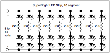
First of all, the resisor's location. Because all LEDs are not alike, your design is at risk of unbalanced light output and damaging the LEDs. You need them in series with each other and a single resistor, as Aedus shows 9 columns of.

Now check the data-sheet for your LEDs, you're looking for "Vfb" (Forward Bias Voltage, usually about 1.6V) and "If" (Forward Current, usually between 10 and 30mA).

The resistor value in ohms, for just one LED and one resistor in series is calculated by:

resistor = ( supply_voltage - LED_bias_voltage ) / led_current

For the one resistor and a string of LEDs, we modify it slightly:

resistor = ( supply_voltage - led_bias_voltage * number_of_LEDS ) / led_current

If resistance ends up negative, you need to either split it into more rows of LEDs in series, or use a higher supply voltage.

Hope this is of use.
 
If you want to use 12V and 12 LEDs I'd do this:


In theory you could do strings of 3, but this leaves such a small voltage that the batteries may quickly drop below the needed potential and current regulation will be poor. You may get away with lower value resistors (280ohm min) but these are more common and the extra current won't gain you much brightness.
 
With those LEDs I'd do this:

1wbxv.gif.png

The resistor value is important, don't just use a resistor which is proclaimed to work, it will not work in this configuration. Don't go lower resistance on my design maybe go up to 47Ohms if you want it dimmer.

You're looking at ~80mA total consumption, I don't think flattening batteries will be an issue. This actually uses less power than strings of 2 which will consume ~120mA.

You can actually go down to 220Ohm resistors on the design above mine and remain in the LED's spec, just.
 
Last edited:
Last edited:
The resistor value is important, don't just use a resistor which is proclaimed to work, it will not work in this configuration.

You're looking at 80mA total consumption, I don't think flattening batteries will be an issue.

This should work, but when the LEDs no longer light don't chuck the batteries out, there should still be useable life in them (with worst case LED Vf each battery will still be 1.425V, fine for most things). Certainly don't use rechargeable batteries in this configuration! For that matter, make sure you use brand new alkaline cells in this configuration.
 
Last edited:
Flat batteries aren't that simple, our circuits will both drop below the LED spec at the same battery voltage (assuming we both use smallest allowable resistors), but yours will reach this point before mine for 2 reasons:
-It draws more current, so discharges the battery faster.
-Since it's drawing more current, the voltage droop on the battery due to your current draw will be higher. The battery will be "more flat" when my circuit drops below spec.

The voltage measured on the battery when you take it out is irrelevant, that's just the EMF, a new Alkaline battery will show about 1.65V.
 
Last edited:
Not quite sure what you're saying. I understand the last points, yes current draw with my arrangement is slightly higher and yes due to internal resistance of the battery this higher current draw creates higher losses.

However, I think you're overlooking that LED Vf is a constant and that LEDs function adequately with well below stated current. Once the supply voltage drops below Vf, the LEDs go out. Once the current drops below 20ma, the LEDs dim, but will not go out, not until under 1ma even. In your arrangement the LEDs will light brightly then go out when the battery voltage has fell, but not by a huge amount. In mine they will dim until the battery voltage is at a point where it is quite useless, which should take somewhat longer even with the higher draw.

Either should work fine in practise mind. A constant current source is more elegant for battery powered systems but is probably over-complicated for the OPs requirements :)
 
Sorry, I've not been clear enough; my second bullet is regarding that: When you draw more current from your battery, the battery voltage will be lower at the same battery charge.

So given that our circuits are potential dividers and over the small voltage range specified for the LEDs their non-ohmic nature could be considered negligible, our circuits have the same critical battery voltage (not charge), mine should be able to operate at a lower charge.
You can ignore the current the LEDs consume for this calculation, it's just a function of the voltage over the LED and to a lesser extent; it's temperature. Remember that current is drawn, not supplied.

A neat design with these LEDs might be a 7808 voltage regulator with a 12V supply. 8V is ideal for 2 of these LEDs in series with a very small current limiting resistor (remember the current limiting resistor wastes power).
The Voltage regulator would allow you to drain the battery to just over 8V and the circuit would see no change at all, you could probably get the cells to burst. But I expect the voltage regulator IC would waste too much power in itself, they're not all that efficient.
 
Ok, I'm not very well versed in batteries, I only know they have an internal resistance which I was assuming was negligibly low for this sort of current draw, apparently not. I was thinking in terms of if I had a variable lab supply and lowered the voltage which arrangement would cut out first.

You can obtain integrated switching regulators now, but I'm not sure how efficient these are either at low current draws.
 
Hey guys, good to see there's different ways I can be doing things:) Seeing as it makes a difference on how many LED's you have on each 'branch' etc, I thought I'd design where I want them and give you some background info.

It's for an architectural model, will be built on a baseboard so I'm guessing the easiest way to do this is to drill 3mm holes where I want lights in the baseboard, put an LED in the hole, then solder it all together so I've essentially got a 'track' going round the outside of the model with LED's within.

Hope the diagram below explains it, it's a ground floor plan - the walls will be translucent acrylic with a pattern etched in so the light can filter through.

So... Looks like I need 10 LED's - 6x1's and 2x2's. Does this help matters?

splancom00model1.jpg

Bear in mind, to save on battery use, you could wire them up as 5x2s anyway. I don't really know much about batteries TBH, only ever used them in an electronics problem once and even then it was only for 20 seconds to program a microcontroller (couldn't take a power supply home).
 
Back
Top Bottom