Trapezia UM400 Restoration - Unique Triple Screen Gaming / Racing / Flight Sim

Soldato
Joined
26 Dec 2009
Posts
9,691
Location
North
Hi guys,

I came of across a system on eBay a few weeks go that was up for sale as spares / repairs, which caught my eye. Never seen anything like it and there isn't / wasn't much information about it online but it seemed cool and thought it would make for an interesting project. Having done many builds over the years whether they be small, large, water cooled etc i'm kind of bored with doing the same stuff with updated components, so this kind of project was perfect to get me motivated.

Here are some links to the system, not sure what its initial use was for but perhaps some sort of editing workstation.

http://web.archive.org/web/20040814221851/http://www.umdigital.com/product/p01_tra_400s.htm
http://www.gtrade.or.kr/buyer/product/TRAPEZIA-UM400.do?productId=C2007-0000006058&categoryId=C0402
http://umdigital.en.ecplaza.net/trapezia-um-400-dcd-system--64174-81150.html

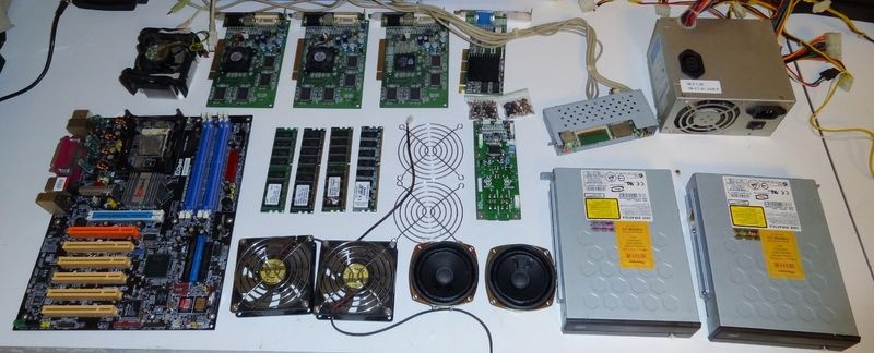
Some quick specs

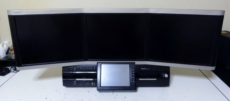
  • 3 x 17" (1280 x 1024 @ 60Hz) Screens = 3840 x 1024 Ultra Wide Screen (115cm Wide with a nice curve)
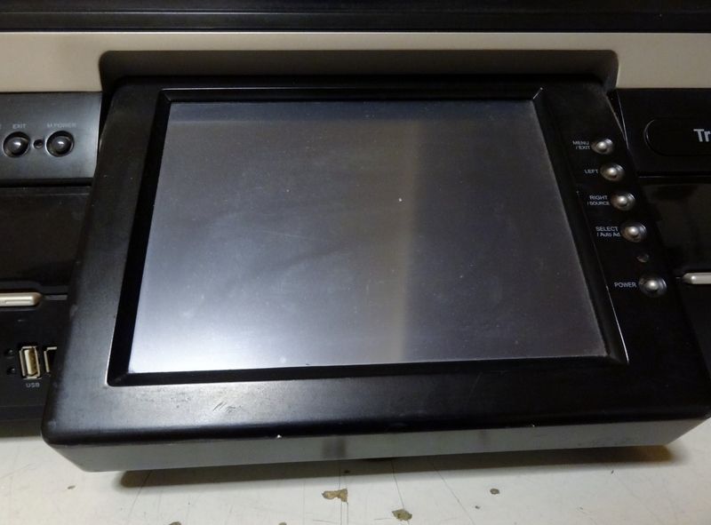
  • 8.4" Touch Screen (Should be great with Windows 10)
  • T Class audio amplifier (Tripath TA2024)
  • 2 x 3" Full range speakers
  • Dual ODD Drives
  • Memory Card Stuff
Hardware wise is very dated, which will of coarse be upgraded.

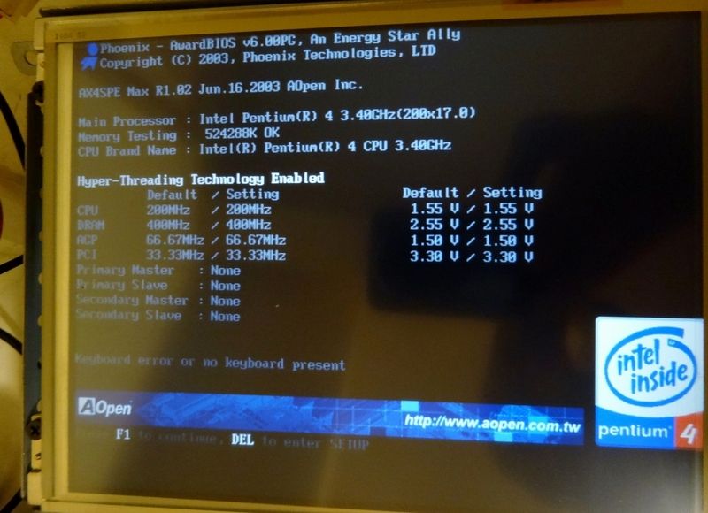
  • Intel P4 3.40GHz HT Prescott LGA 478
  • AOpen AX4SPE Max LGA 478
  • 1GB DDR 400Mhz
  • 3 x NVidia MX 440 SE PCI Graphics Cards
  • ATI Rage Ultra 128mb AGP Graphics Card
  • 460W Seasonic PSU
  • 2 x Pioneer DVD Drives
Ancient stuff but still cool, 4 GPU monster :)

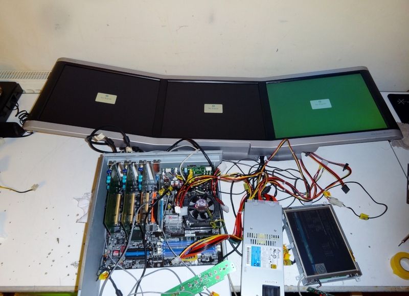
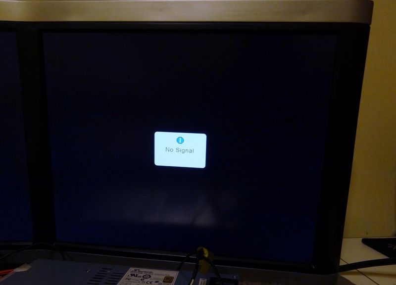
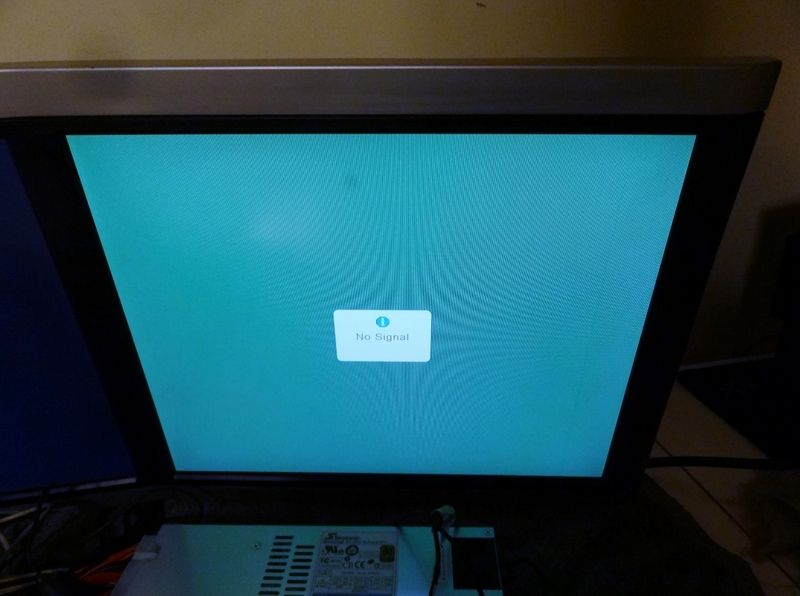
Now as I mentioned when I got the system it was spares / repairs aka it wasn't working, been sat in a garage for a while it seems. So my first goal was to get it up and running to make sure there's something to work with if I take it any further. No point continuing if the screens are dead. So over the last few days I have been prodding, probing and diagnosing the system to figure out whats up with it (with the help of the guys over at badcaps, thank you)

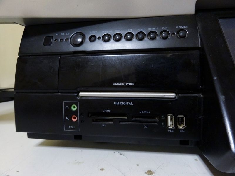
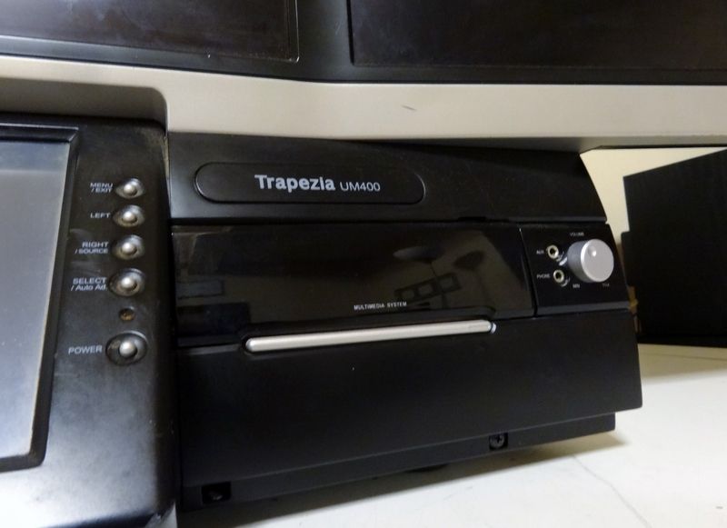
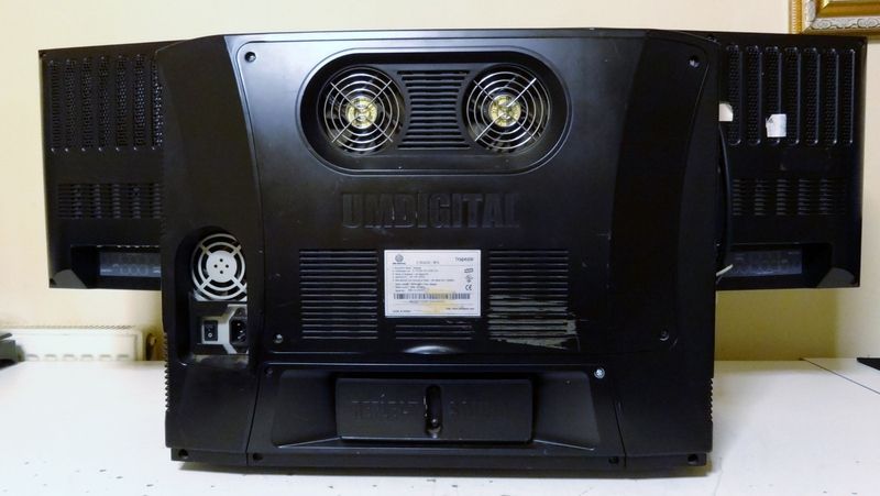
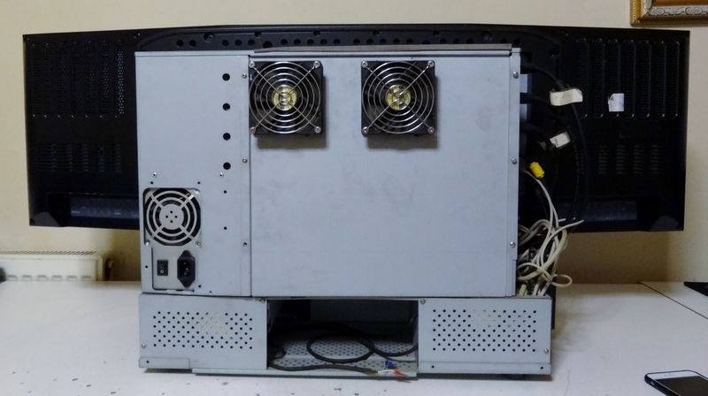
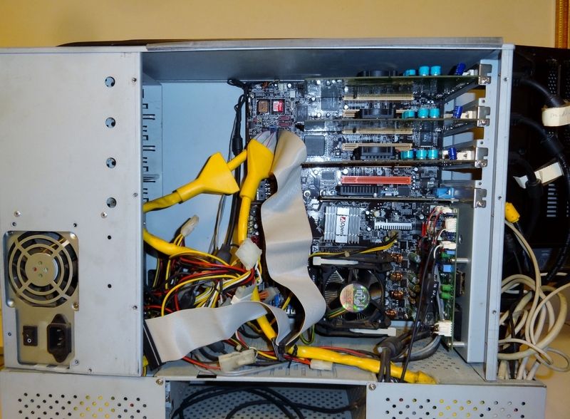
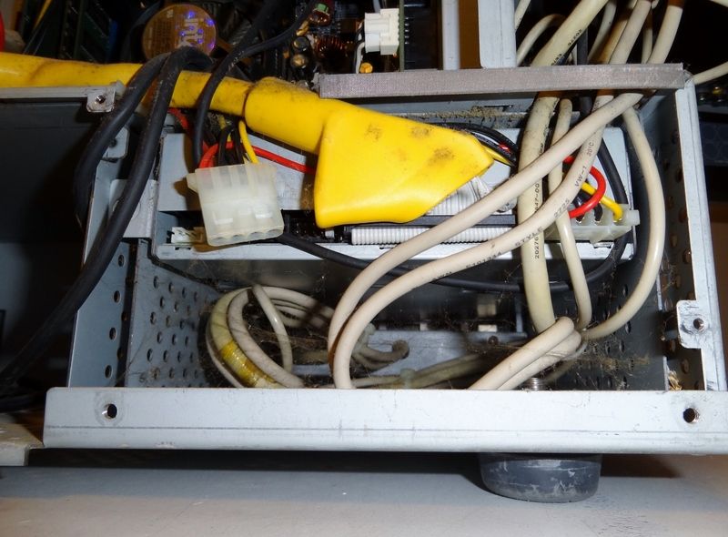
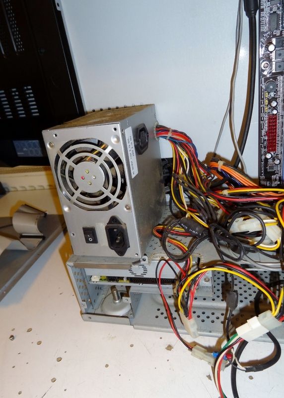
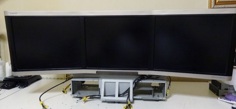
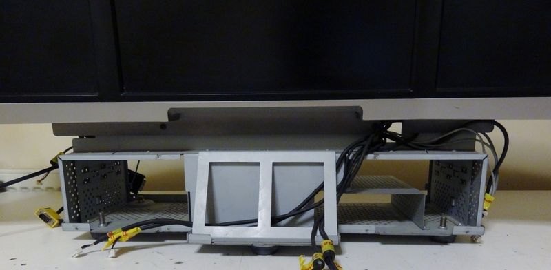
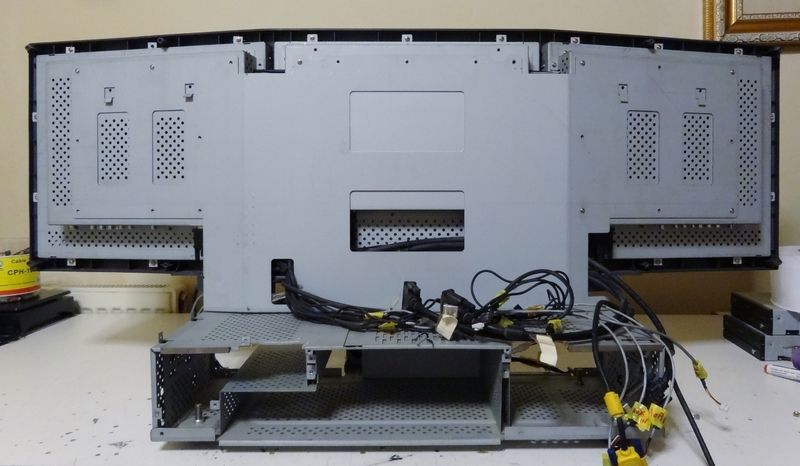
Here are some images of the system as I got it
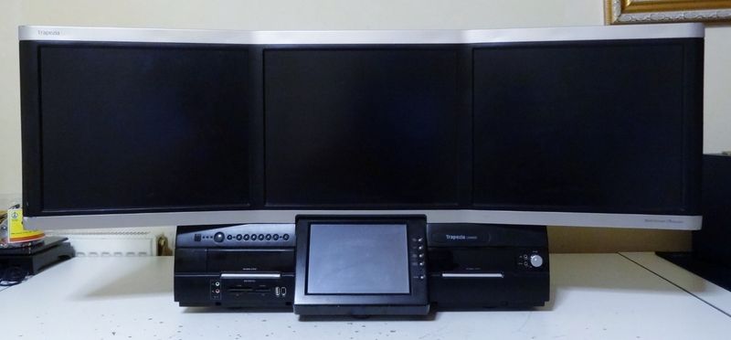


As you can see not in a very good state, absolutely filthy, had at least a dozen or so creepy crawlies living in there and I hate spiders. Thank god I had the sense to spray the entire thing with some Raid bug killer which just left me only having to vacuum up their carcases rather than having to set the house on fire :)

Continued
 
Last edited:
First things first, I photograph everything as there are way too many connectors and cables for me to remember what goes where. Tagged all cables and connectors with numbered labels and I can begin to mess with it.

So after a bit of prodding I've narrowed it down to a dead PSU, great that's something that would have been replaced and saves a lot of trouble shooting if that is the only issue. Only issue with that is the PSU is custom and has loads of custom connectors powering everything. For example the all the monitors are powered by the PSU off the 12v rails, something else is powered off a 5v rail etc so isn't a simple swop over PSU and test. So did a bit of bodging of all the connectors and my spare PSU to get it all powered up and tada she lives, well kind of anyway! So I know it lives to some capacity it's time to strip the thing every bolt and screw and take it apart and give it all a thorough clean.


All non electric stuff took a bath and got a good scrubbing, wiped everything down with isopropyl including all circuitry, dusty / oxidizing connectors and cables. Starting to shape up now and is nice all clean looking presentable. So put it back to a partially assembled state to test it further.


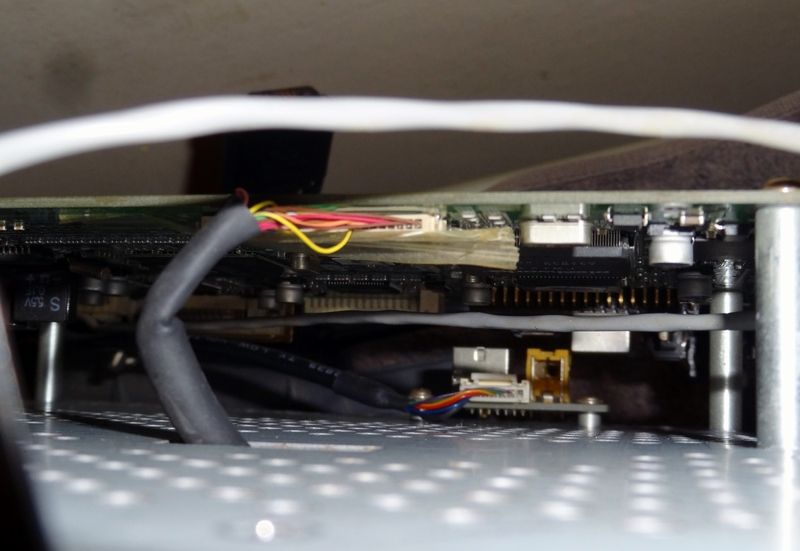
One of the screens was displaying an intermittent problem, which could have been serious, but thankfully was just a dodgy ribbon cable. So removed it and cleaned both ends and its socket, put back in and secured with some hot glue as the original tape and turned to chalk. Working as good as ever now.

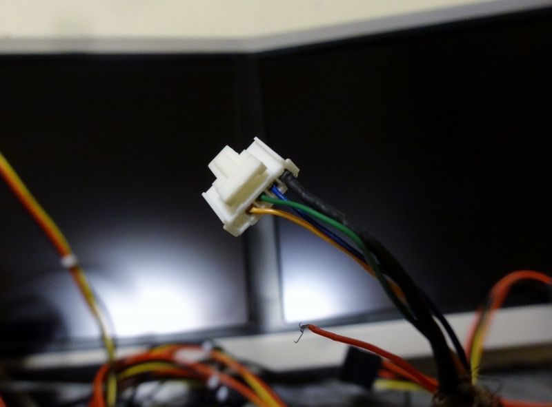
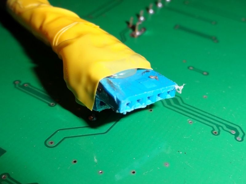
One of the internal cables used to control all 3 larger screens had a dodgy connector (possibly done by me) which was a pain in the butt as is a JST connector and really finicky to work with. So settled on modding a USB 3.0 header, cutting it down to 5 pins and soldering the original cables over to it giving it a nice strong connection. Worked a treat and now got full control of the monitors. I'm happy with it but might change it later on, not sure yet.


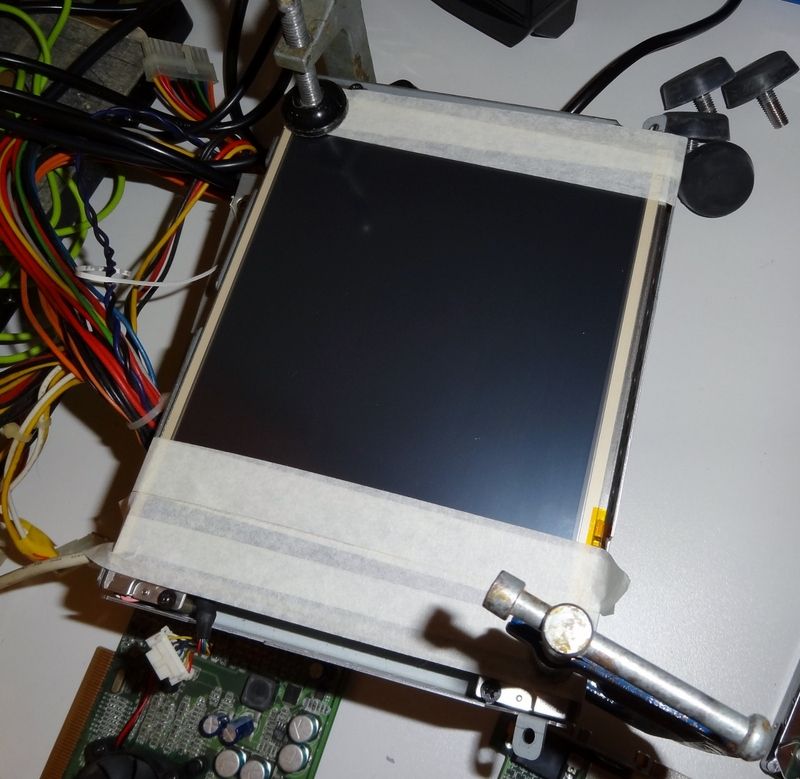
Touch screen digitizer glue had all tried up and was loose so took it apart and scraped off all the old glue and ordered some double sided tape used on mobile and tablet digitizers. Cleaned up both digitizer and screen with some isopropyl before putting on new double sided tape. Got it clamped up and will leave for 24 hours to cure.


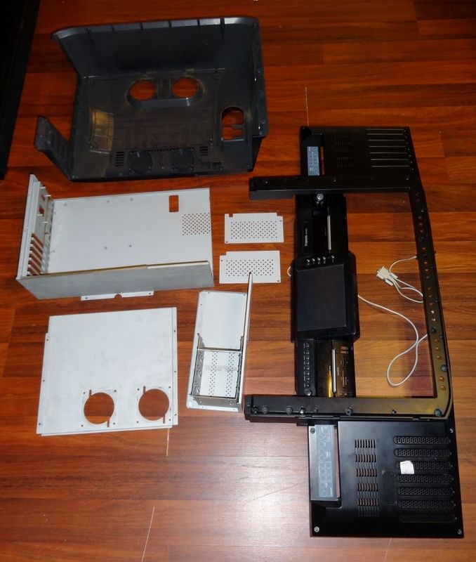
That's it with the problems I hope. And since I had it all apart, and it is literally apart down to the last bolt right now I thought why not have all the bland mild steel parts powder coated. Now I am on a bit of a shoestring for this stage of the build or shall we say restoration but given I probably wont have the opportunity to have it apart like this again, I decided to get it done. So popped down to a local powder coaters yesterday and had a chat with the guy who quoted around £60 for 18 individual parts from large to small. Which isn't a lot of money especially considering I was thinking of spraying myself which would have come close or even possibly exceeded £60, taken forever with a lot of work involved. So yea £60 not too bad. Will get parts back on Wednesday.

That's where I am at now. So things to do at this stage of the build, what' next

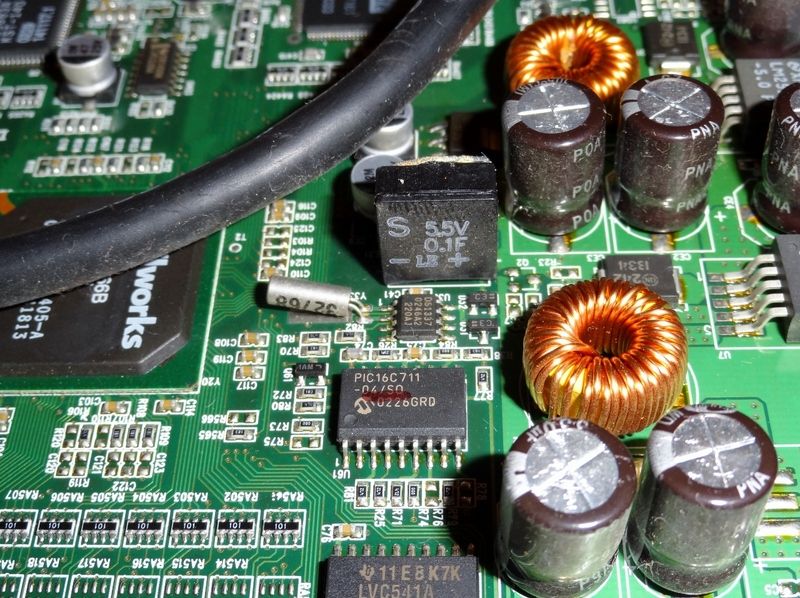
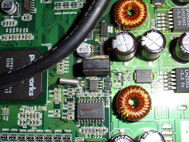
  1. Replace the blown cap when replacement arrives
  2. Mod the old USB 2.0 / FireWire ports and replace with duals USB 3.0 ports. Might have to slightly mod the mould for the FireWire port as it is a different shape to USB
  3. Mod all the power wiring. 6 x Cables that require 12v and 5v for the monitors and amplifier, into a single braided ATX style socket. Will use a 20pin ATX connector and remove 4 columns leaving it with 12 pins. That way when I get a new PSU for the next stage of the build I can use a few molex cables and mod into a female end of 20pin ATX connector.
 
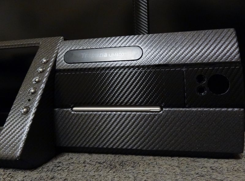
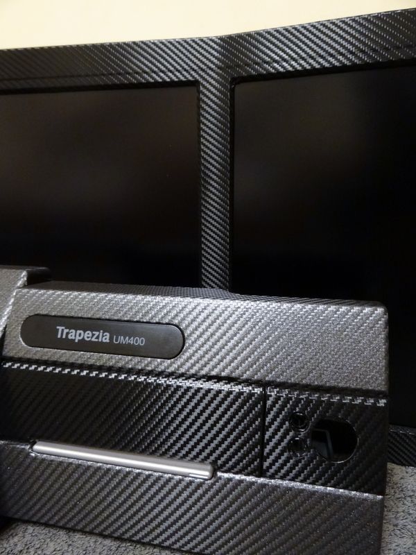
So given the system at stock looked like a 90s VCR I wanted to somehow spruce it up a little bit. Now I'm not the greatest fan of vinyl wrapping, and have thought before it sometimes looks a bit tacky but given this build is race inspired I thought a carbon fibre vinyl wrap would be perfect.

I wanted a two tone effect with black for the monitor side, as you want the bezels as unobtrusive as possible, and white for the bottom half. So popped down to local wrapping place and had a look at some different coloured wraps in the flesh but the white looked a bit cheap / tacky in person, so decided against it. Loved the grey so decided on two tone black / grey. They didn't have any 3m Di-Noc stuff, which ive read is the best, but the guy there said they have used all branded wraps and they felt that Averys wraps were the best, easier to work with and much cheaper. I had a look at some samples side by side and I couldn't tell the difference, and if it's good enough for them it's good enough for me. So bought a meter x 1520mm of each. Top bloke there sorted me out with a Swann Mortan scalpel and blades, a tac cloth and one of ther sqeeges for free.

When I showed him what I was wrappin I could see it in his eyes, "you gonna **** this up" and he wasn't wrong lol :)

Now I have to say this, this was by far the hardest mod I have ever done. Tear your hair out hard. I wish I knew how hard it was going to be and I wouldn't have bothered. I thought the top half was going to be harder but the bottom half turned out to be virtually impossible. The first day went completely too waste, spent all day wrapping with a full piece, tore it off started again and ended up tearing that off. On the plus side that full wasted day I learnt how to work with the stuff a little better. So next day I decided to break the bottom half into three sections. Left, centre and right and tackled each separately which did the trick. Now its not perfect and have tried to hide as much error I could underneath where it cant be seen. The perfectionist in me just said nope :(


Still extremely pleased with the outcome, well worth the £40 for a full transformation. Got a bit of cleaning around holes / ports to do, but more ales done with the wrapping.

The powder coating is also done and photos to follow in next post shortly.
 
Last edited:
Really impressed with the powder coaters, for £60 you cant complain. Excellent uniform finish.


Went back even further to the rear assembly, left the LCD housing though as didn't want to mess with the connector ribbons anymore than I had to. Though is covered by the housing.


Last edited:
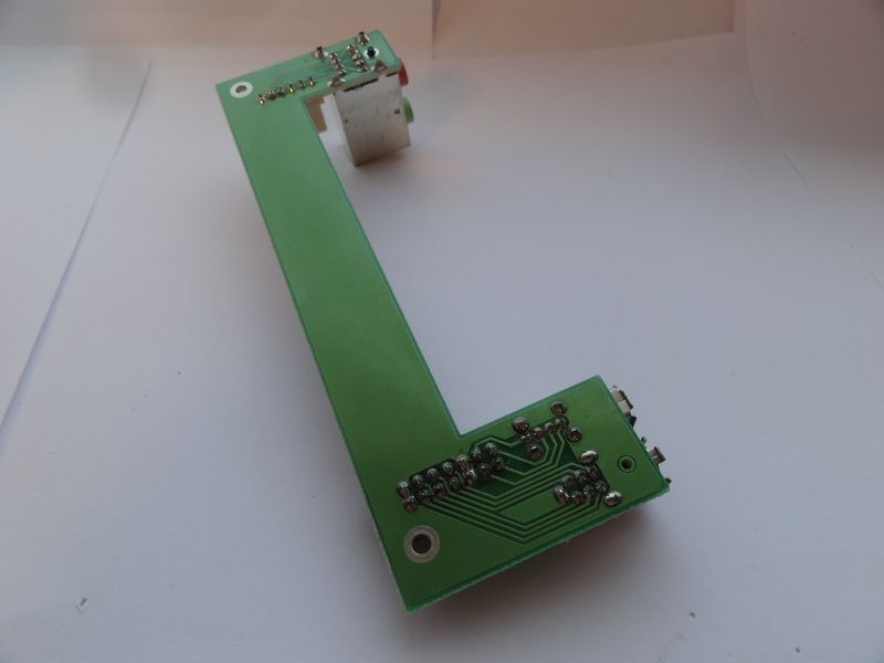
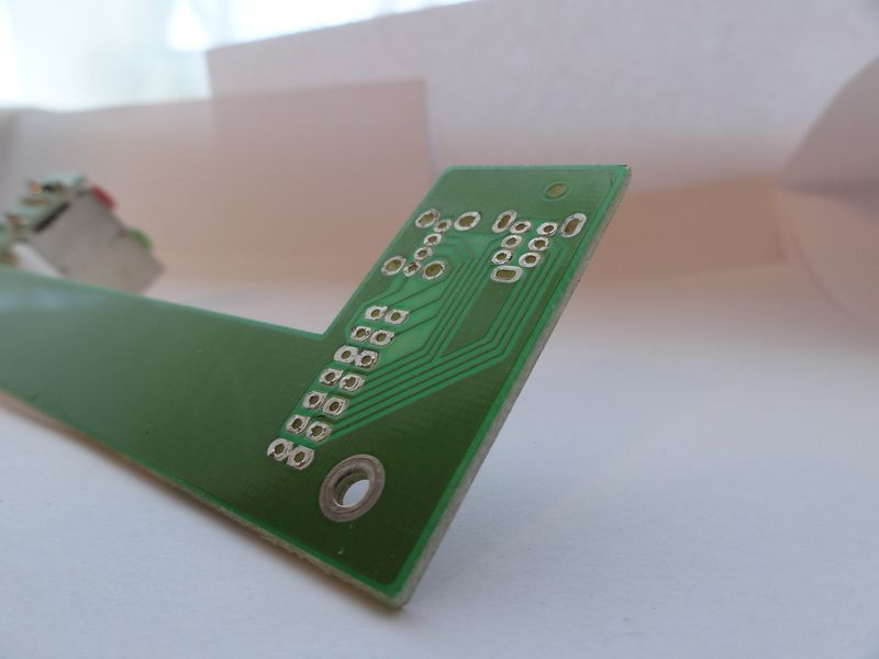
and finally for today the USB ports

original board


underside


desoldered


my solution, this cute little USB 3.0 board


And I couldn't have cut it down to size any better myself, what are the chances it is literally a perfect fit.


freshly powder coated casing


and how it will fit


just need to cut the old section of the PCB off, and screw this in place
 
Last edited:
Back
Top Bottom