USB +12v

Associate
Joined
5 Feb 2009
Posts
405
Do you think it is possible to deliver +12v through a standard USB PCB mouting to a circuit board ?

Just am thinking of creating my own PCB for a project and have seen USB to PCB connector, so thought I mite be able to make a molex to USB connection using only the +12v and the Ground.

Regards
-Ninja

P.S not sure if this is the right section for this or not.
 
I think they are rated around 30Vac so yes it would be OK.

Questions is, why would you wanted to use a connector commonly known to use 5v to connect 12v to a PCB? Make sure somebody plugging this into a PC or a 5v supply by accident doesn't mess up either bit of kit.
Another alternative is to convert 5v USB to 12v with a boost PSU.


Frankly there are plenty of better power connectors out there.
Even the molex on the back of an old CD drive would be a better choice.
 
Voltage is only half the story, how much current would you be trying to put through the connector? It is definately possible but you would not be able to push as much current through the connector as at 5V.

It is well worth remembering standards exist for a reason, if someone plugs a USB drive in it will get toasted and they won't be happy! Have you considered regular power connectors like the 2.1mm power sockets? If you aren't using the data pair then you could use a standard power socket and kill off such ambiguity easily and for a similar price. You can get Molex board mount connectors too, not sure if it counts as posting for competitors or not so use trust if you want some part sourcing help!
 
I've looked at one or two specs and the USB PCB mountings seem to be rated at 1A so watch out for that if your project requires more. Considering USB is only meant to carry 500mA or just a bit more then the current spec is no big surprise.

It will work of course but I too think you are asking for a potential issue using a proprietary part like a USB socket with 12v rather than 5v.

What about utilising some standard pitch fan header connectors? You can obtain Molex to fan header converters easily enough and can also buy PCB mounted ones just as easily.

http://www.overclockers.co.uk/showproduct.php?prodid=CB-007-GE&groupid=1929&catid=153&subcat=
 
Last edited:
I have only asked because I have a PCB mounted one spare so was just wondering about the limitations, this device is only for me just to let you all know it is to power an array of LED's for a project within my case.

If anyone is a circuit design pro then this might be more helpful.

My project is having 2x 2 Blue 5mm LED's around HDD, and then 4x 2/3 Blue 5mm LED's around DVD drives. I am not sure whether to have them running off individually or as branches of 2 or 4 ?

Obviously it will either need to run off 12v or 5v. It might be better to have this stored within two separate units, one for HDD and one for DVD Drives.

From looking at some online resopurces using a full molex (+5v, ground, ground, +12v) I could have:

For +12v / ground (4x 3 LED Array)

+----|>|----|>|----|>|---/\/\/----+ R = 120 ohms

For +5v / ground (2x 2 LED Array)

+----|>|---/\/\/----+ R = 100 ohms

So would this be better off going through a Molex to PCB fitting ?

If anyone could point me in the right direction of PCB mounted fittings (i.e. Molex connectors) that would be very useful, I don't think this will breach OcUK's T&C's because it is not something they are directly selling ? Correct me if I'm wrong.

Edit:
LED's Stats:
5mm Blue LED
diode forward voltage: 3.2v
diode forward current: 20mA

Regards
-Ninja
 
Last edited:
Without seeing a spec sheet for the LED's I'll trust you've picked the resistors properly. Do you have these so I can check and ensure the actual current load you'l be applying to the rails?

As you appear to want both 5V and 12V I would definately go with the molex power connector as the pinout includes both 12V and 5V in it's designation. Also the USB spec only addresses the power rating for the outside 2 pins as these are the power rails, the inner 2 contacts expect to see no more than 350mA as they are for differential signalling; whereas the Molex plugs will take ~3A to 5A IIRC.

Regarding supply, a well known auction site item ID 320810534463 should be roughly what you are after as a thru hole mounting system, the UK supplied ones aren't apparent if they are SMD or thru hole and the cheapest listing is all SMD.


Edit: the spec sheets are important for optimising the array too!
 
Last edited:
Yeah I just spotted that, make sure you pick up 1/4W or better resistors, those would be fine on the power rails of a USB connector on their own. I've got a copy of the full USB connector spec on my works' laptop. I guess my supplier suggestion earlier depends greatly on how quick you want them! Do you have the specs for the smaller LED's?
 
I have seen this 1/4W about a lot when looking what does it actually mean, it has been 6 years since I did basic electronics lessons (GCSE), is that like the silver/gold ring around the resistor ?

And being my impatient self, was looking for a supplier by end of the week haha :D

Just had a quick look myself at 300490873969 is that the sort of thing I could need ? also if you need any more specs 390107299323 is the actually LED's I have.

What are my options for arrays of LED in this setup.

Regards
-Ninja
 
A 1/4W resistor basically is rated to be able to handle 1/4w of power dissipation before it'll break down to heat. 1/2W and 1W resistors tend to grow in size and expense.

Given your circuit is 12v and your diodes are 3.2v the resistors must at most handle 8.8v at 30mA which is just about 250mW, which is where your 1/4w comes from.


It's better to have multiple LEDs in series as less energy is wasted being dumped through resistors.

So 12v sources are better than 5v as you can have 3 LEDs in series and only need to drop 2.4v @20mA through your resistor. 150 ohms would give near 20mA.

You could have course just solder your molex leads directly to your PCB if you don't fancy sourcing a panel mounted socket.

The silver and gold rings specify tolerance rather than power rating.

Have you seen this one? http://forums.overclockers.co.uk/showthread.php?t=18172810

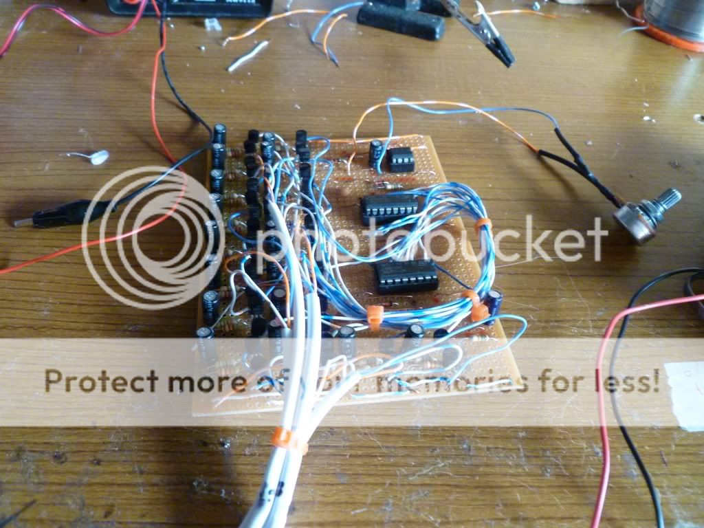
In a recent project I just soldered a big bunch of wires direct to my board and fitted a cable tie or two to act as strain relief. Once in situ the wires would not be pulled so this is more than sufficient under these circumstances.

finished-pcb2.jpg
 
Last edited:
1/4W means the resistor is capable of dissipating a quarter of a Watt (250mW). The gold or silver band defines the tolerance the resistor is made within, gold is +/-5% and silver is +/-10%. Basically the larger the resistor the more power it can dissipate, using a 1/2W resistor would be fine but a 1/8W would be bad news as the LED's would overheat and melt (or just ease to work dependant on the load profile).

The item I listed is definately a PCB connector you could work with with the simplest mounting technology from your PCB designing front, surface mount is a pain even with the kind of soldering equipment I have access to at work! You could try sending a question to one of the UK only suppliers like this one: 300490873969. I have bought off that seller before but he took ages to leave feedback (sent items same day though) so not sure if it would be any faster to ask. It looks like they are through hole but I can't be 100% sure so you'd be taking a risk on those or accepting the delay whilst he answers the question.

Anyway, that is the kind of thing you want unless you are going to solder wires to the PCB board, and if that's the case I'd advise you use cable ties to provide some strain relief on the joint. Would you like me to elaborate on this kind of strain relief for you? I don't mind doing so if it is wanted :)
 
Last edited:
Back
Top Bottom