Simplistic & cheap PWM-to-3pin-fan converter

Associate
Joined
24 Aug 2012
Posts
11
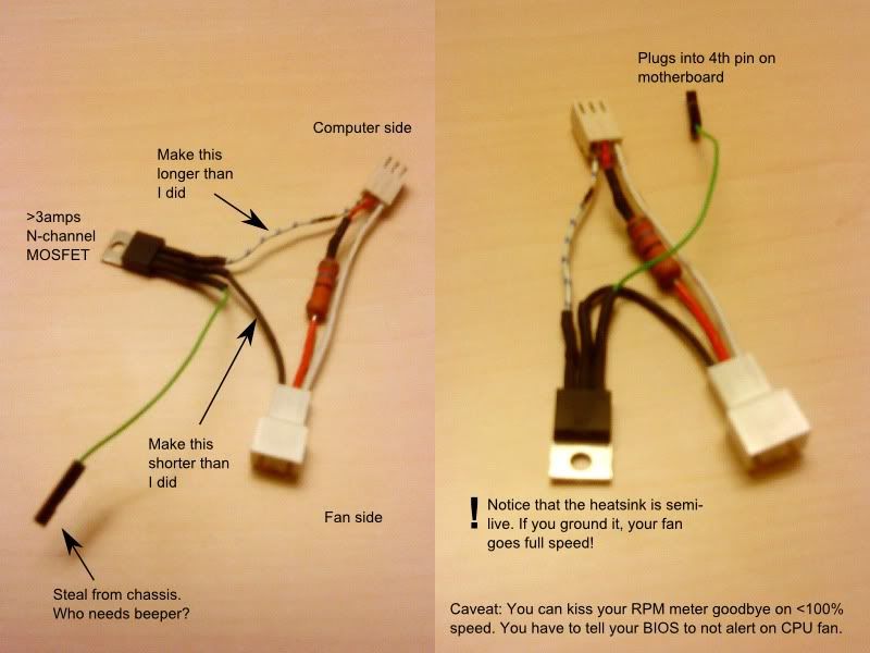
Note that this is absolutely as KISS as it gets. Particularily, you can kiss your RPM readings goodbye on anything other than 100% speed.

If you want better, Tealc's http://forums.overclockers.co.uk/showthread.php?t=18421145 is for you.

Note to future readers with 3pin fans & 4pin headers: Before you do anything else, check if your BIOS has a setting for 3pin/4pin control. If it does, you can probably just set it to 3pin and stop reading now.


4pin-pwm-to-3pin-fan.jpg


Things you need
  1. A resistor package suitable for your fan, Zalman's package should handle most everything with its beefy 56 ohm resistor (7v operation)
  2. A nice big N-channel MOSFET. 3 amps or bigger and you don't need extra cooling. Minimum 20V throughput. The max Gate voltage can be between 6--20 volts, but don't go bigger than that or the 5V PWM pin feed becomes too low to open the MOSFET properly.
    My TV repair shop gave me an IRF630 which is complete overkill. I like it.
    Absolutely best is if you can get one rated as logic level input (but still drives plenty of amps)
  3. Steal one connector from your PC chassis.

My version drives my Zalman 9700 CPU fan from 40% PWM up to 100%, resulting in about half of max speed due to the resistor. The action sounds sort of linear-ish, which probably means it isn't. (Sound level increases exponentially with RPMs)

If you like, you can short out the resistor entirely for full range action. Be aware however that your fans will start spinning at 10-15% PWM and that the curve becomes very aggressive. You'll be going fairly high on RPMs at 60% already. This means that standard BIOS fan controls will likely drive high RPMs throughout, so you might want to be able to tune the PWM curve yourself (via e.g. SpeedFan)... unless you simply want high RPMs, of course.


About the RPM monitoring: no, there is no way to get working RPM monitoring with this few components, you can forget it. With 3 (and switching the MOSFET for a P-channel in high-side driver configuration) you might be able to get it working. But don't take my word for it. Perhaps with a 10-100uF capacitor parallel with the fan? Unknown & untested. One definite caveat is that the heatsink goes +12V live.

Caveats:
  • Your BIOS will likely "F1 to continue" you in the face with this adapter on the CPU fan because it can't see RPM readings. Disable the monitoring in the BIOS!
  • Tools like ASUS Fan Xpert will probably hate you too for the same reason. SpeedFan works!

Wins:
  • You can actually turn your CPU fan completely off!
 
Last edited:
Soldato
Joined
13 Jul 2009
Posts
7,177
Location
Llanelli
Nice work. But allow me to give some helpful criticism if I may. I may be seeing this totally wrong though so please forgive me if I'm way off. :)

I think you need a diode with this one, otherwise the back EMF as you switch the fan on and off at 25000 times a second will fry not only the FET but your motherboard as well, or at least eventually anyway.

You should also consider having a resistor 500-1k between PWM and gate of the FET. This will help prevent the FET grabbing too much current from the PWM controller as it fills the gate. You may also need a pull up or down resistor (not sure which) to make sure the FET switches fully off and doesn't hang around in the linear region.

You are also using the FET in it's linear zone so it will waste energy as it's not fully switching. Better to use a logic level IRL type FET that can switch fully on at lower than 5v.

Saying all that though I can't actually get this simple circuit to work under simulation and produce a waveform I like the look of. I dread to think what sort of spikes and ripple the switching is giving you. Thinking about the pull down/up resistor thing though makes me think that the FET is actually not fully switching and gives some linear control to the fan, this could be why simulation doesn't work as the FET models are probably too perfect. I will breadboard this tomorrow and see what I get. I don't have an oscope so will be guessing what's going on.

Maybe this is switching between 5v and 12v as your PWM cycle goes on and off.

When I first started looking at PWM to 3 pin conversion I thought it would work just by slapping a mosfet on the 5v PWM and having the fan on the high side of the switch but it didn't work at well with a motor.
 
Last edited:
Associate
OP
Joined
24 Aug 2012
Posts
11
Thanks for the inputs - it's always very appreciated to know there's someone out there willing to doublecheck my think!

I worried about all the things you listed and researched them.

I found answers in http://www.formfactors.org/developer\specs\REV1_2_Public.pdf

PC fans are required to have diodes in them. No back EMF is allowed.

The PWM pin output is specced to source max 5mA, suggesting a minimum 1kohm resistor. My original spec had a 1.3k+3.7k pulldown but that shot me spectacularily in the foot when I ended up trying to drive my gate with 2.5 volts (measured!). Turns out my motherboard has a 2kohm resistor on the PWM pin. Oops. The MOSFET also went hot as heck. Running it the way I do now, it's actually cold to the touch. (And no I didn't check the charts when I picked it up in the shop, REALLY my bad with the pulldown mess.)

You're very right that my beefy MOSFET is not fully open at 5v, but check the power curve and you'll see that it'll pass several amps already at that point so no problem there :)

But I will cede the general point - a MOSFET with a logic level-rated input is your best bet, especially if it's not as overkill as mine.

You're also fortunately wrong in worrying about the 0 signal. The PWM spec clearly states max 0.8v low.

I have no idea why your initial circuit doesn't work. I've ran 3 different fans on 2 mobos with this now - with and without resistor:
- An old 7000 series non-heatpipe Zalman CPU cooler
- A 9500 zalman CPU cooler
- A Noctua NF-S12B case fan

I also did tries with a (33u cap + 56 ohm) in parallel with the fan. Also works, but the end result is just even more RPMs early in the the PWM% spectrum.

Damn shame that you don't have an oscope - I don't have one either :(


Edit: Oh and you're right about the MultiSim curves. They look absolutely atrocious. But MultiSim only has simplistic motors, not ones with lots of logic in the hub like any PC fan has.
 
Last edited:
Soldato
Joined
13 Jul 2009
Posts
7,177
Location
Llanelli
Thanks for that info about PC fans, I have been meaning to check on that.

I've measured the voltage to gate on mine with 1k, 2k and as much as 30k and it's always a factor of duty cycle between 0 and 5v, with 5v being 100% duty cycle and 1v being 20%. My multimeter is far too slow to pick up the peak voltage of the PWM. Saying that though I have measured only on my 555 PWM circuit off pin 7 and I haven't checked exactly how much that can source. I haven't measured the voltage off the PWM pins.

I'm really happy it works for you though and look forward to testing it out myself.
 
Associate
OP
Joined
24 Aug 2012
Posts
11
Aye, I would fully expect a multimeter to average out the voltage over the duty cycle, otherwise it would be completely useless when any kind of harmonics are involved. (Four flickering 7-segment digits, yay)

I measured my own 2.5V above with 100% duty cycle.

I'm not surprised you're getting 5V@100% all the time on your 555 circuit - it doesn't have an internal resistor.
 
Soldato
Joined
13 Jul 2009
Posts
7,177
Location
Llanelli
How did you measure the 2k resistor on the PWM? Don't you normally have to take components out of a circuit to get a proper measurement? Just interested that's all.

I managed to get your simple circuit working anyway but it seems I don't really have a mosfet suitable. BS170 works but is clamped at around 10.5v even with the resistor in the 12v.
 
Associate
OP
Joined
24 Aug 2012
Posts
11
I didn't measure. I just did the math: 5V -> X internal -> 1.3k -> gate connector -> 3.7k -> gnd. Measured 2.5V at gate. Gives X=2ksomething.

The IRF730 you had should work?
 
Last edited:
Soldato
Joined
13 Jul 2009
Posts
7,177
Location
Llanelli
The IRF730 you had should work?

Couldn't find it. :( I never put stuff away after myself.

If I have a good dig I might find it, or something similar. I've got about 4 or 5 large power mosfet types tucked away somewhere.

I think perhaps that the PWM voltage isn't necessarily always 5v as the fan spec is supposed to pull it up to 5v. One circuit I was thinking of building was a little more complicated than yours, used a LM78L05 to do the pull-up and that had a similar 12v/0v output and wasn't restricted by whatever the PWM output voltage was.

Of course by the time I got the regulator in I'd built the one with RPM feedback so never got around to it.
 
Associate
OP
Joined
24 Aug 2012
Posts
11
I think perhaps that the PWM voltage isn't necessarily always 5v as the fan spec is supposed to pull it up to 5v.

Hrmmmm I just checked the 1.3 spec (been reading 1.2) and it suddenly says to pull up, yes (whereas 1.2 does not).

Do you have any non-ASUS mobos to measure on (with 100% duty cycle obviously). Mine are all ASUS at the moment.

Iffy work though, pulling up a voltage when you don't know the internal resistance. Unless you go with silly high resistances of course. (Assuming the voltage you have to work with is non-5V obviously. Like in a fan where they have 12v. Unless you start mixing in zeners. Sigh.)

Edit: ******, it seems Intel is up to rev1.61 on PWM, but it's all secret-hushy on their site and needs a password.
 
Last edited:
Soldato
Joined
13 Jul 2009
Posts
7,177
Location
Llanelli
Hmm had a poke around with my multimeter on my CPU PWM pin and it's showing 4.87v no matter what the duty cycle. That's not as I expecyed and I strongly suspect that Speedfan might be modifying the way the PWM pin works to suit it's own needs, and might go some way to explain why I need to have 45% duty cycle where 30% was working to the same speed with ET6. I'm stuck with Speedfan as ET6 crashes punkbuster in a game I play.

Next I probed the GPU PWM of my HD6950 and that shows what you'd expect when you measure PWM with a multimeter. 3.5v at 100%, 1.79v at 50% and 0.75v at 20%.
 
Last edited:
Soldato
Joined
13 Jul 2009
Posts
7,177
Location
Llanelli
Just downloaded the trial version of Multisim 12 to view the file. I never came across that model before.

Loving the -87v on the oscilloscope though.

PWM seems to be working backwards in that example too. Higher duty cycle leads to lower switch on time, but greater duration of the negative peak voltage, which must be a product of the inductance in the motor model.

It looks like your experience with circuit simulation is greater than mine.
 
Associate
OP
Joined
24 Aug 2012
Posts
11
Yeah like I said in the schematic, I have the +5V pulse source set up "backwards" with +5V being the normal state and 0V being the pulse. That way I can run it on +5V for 100-300ms at the start to rev up the motor. (Not pulsing during that time makes the sim run MUCH MUCH faster.)

And yes, the -87v on the sim oscope is super awesome. But if you graph wattage in a manual sim you'll see that there's absolutely no amps involved.

As for sim experience.. nahh, I mostly just swear and tinker until I get it to behave.
 
Back
Top Bottom