****Gigabyte X79-UP4 Review****
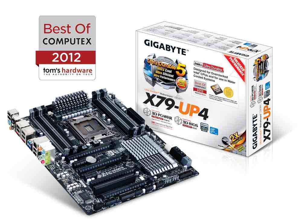
Ocuk product page - http://www.overclockers.co.uk/showproduct.php?prodid=MB-414-GI&groupid=701&catid=5&subcat=2174
Gigabyte homepage - http://uk.gigabyte.com/products/product-page.aspx?pid=4288#ov
The X79 chipset from Intel is aimed at the high-end consumer market and is designed for power users who use their PC's for more than just gaming and some simple video editing etc, If you do a lot of heavy workload on your PC such as editing/rendering then this is a platform you maybe interested in as the CPU's available for it consist of not only quad core processors but also Hex core and even eight core CPU's such as Xeons (provided the board supports it). Hyperthreading is also present on nearly all the CPU's compatible with X79 motherboards.
The GA-X79-UP4 CPU support list can be found here - http://uk.gigabyte.com/support-downloads/cpu-support-popup.aspx?pid=4288 -you will see a few Xeon CPU's listed as well, some of those are eight core variants such as the Xeon E5-2680 which does include Hyperthreading making a total number of 16 threads.
As the board features Ultra Durable 5 it has IR3550 PoweIRstages powering the CPU also, theses chips are rated at 60A each yet remain cool and efficient. They have won a few industry product awards also


Boards with "UP" in the model name will have Ultra Durable5 and these PoweIRstages.
Packaging and accessories.
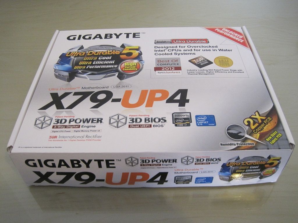
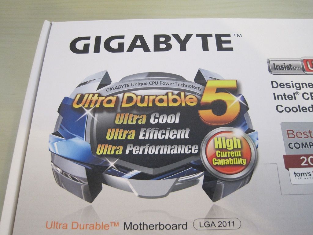
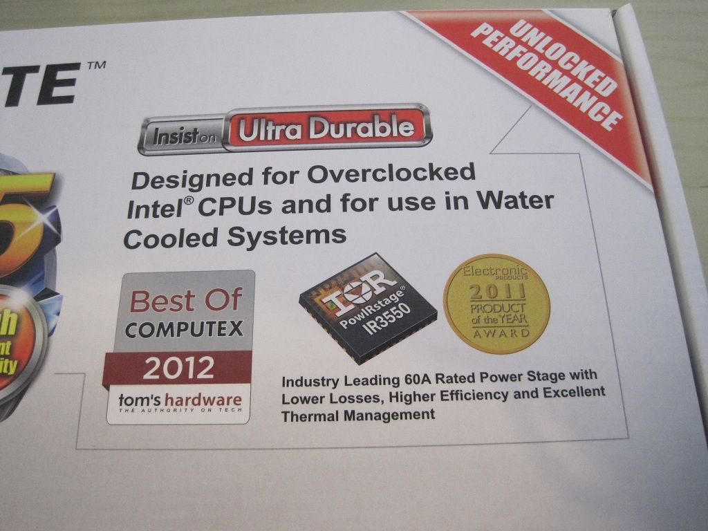
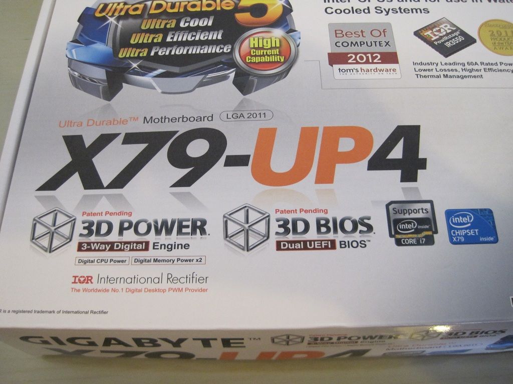
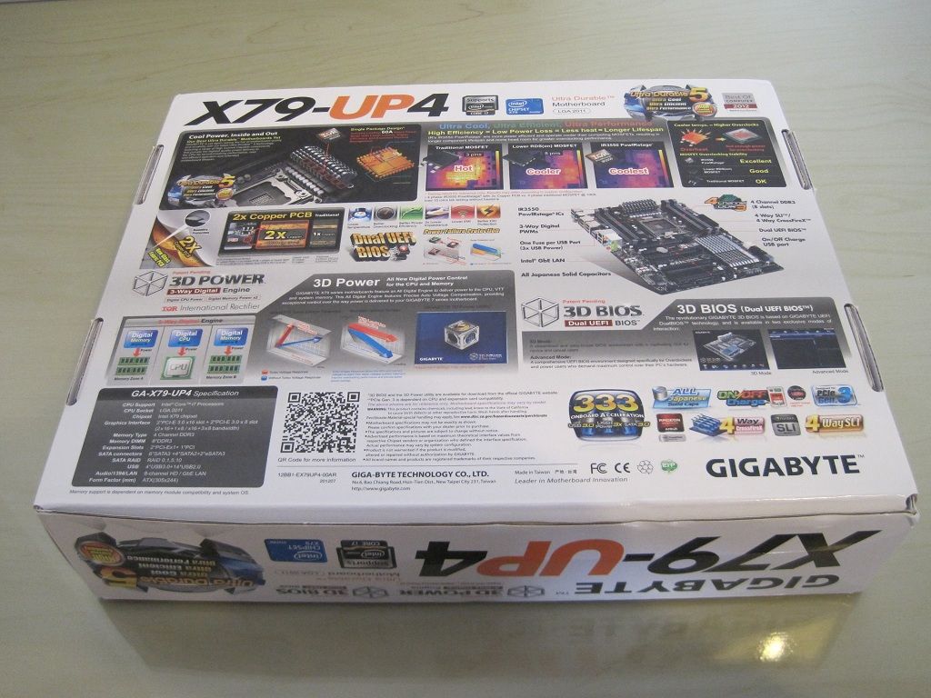
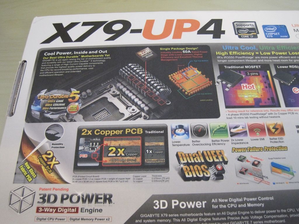
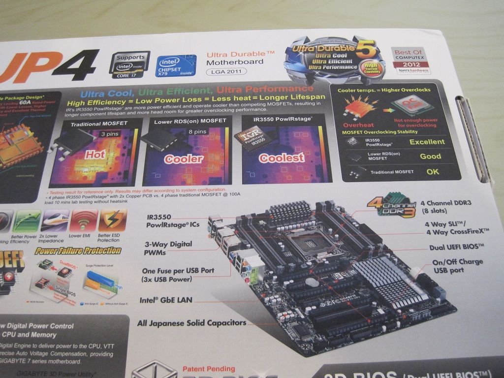
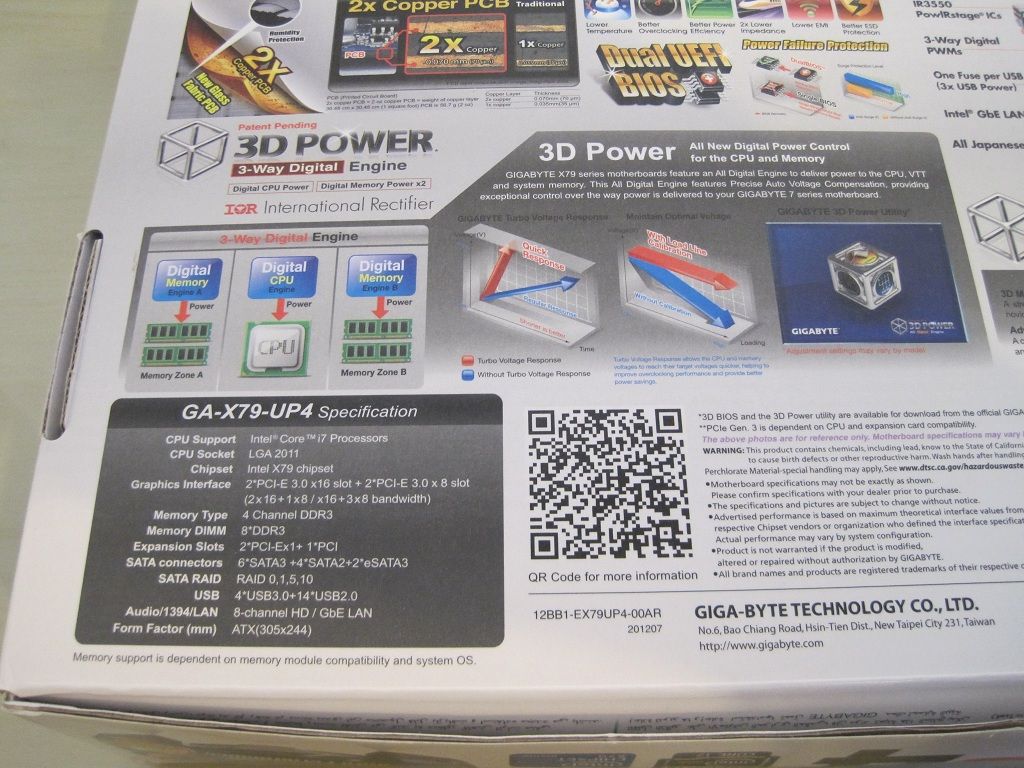
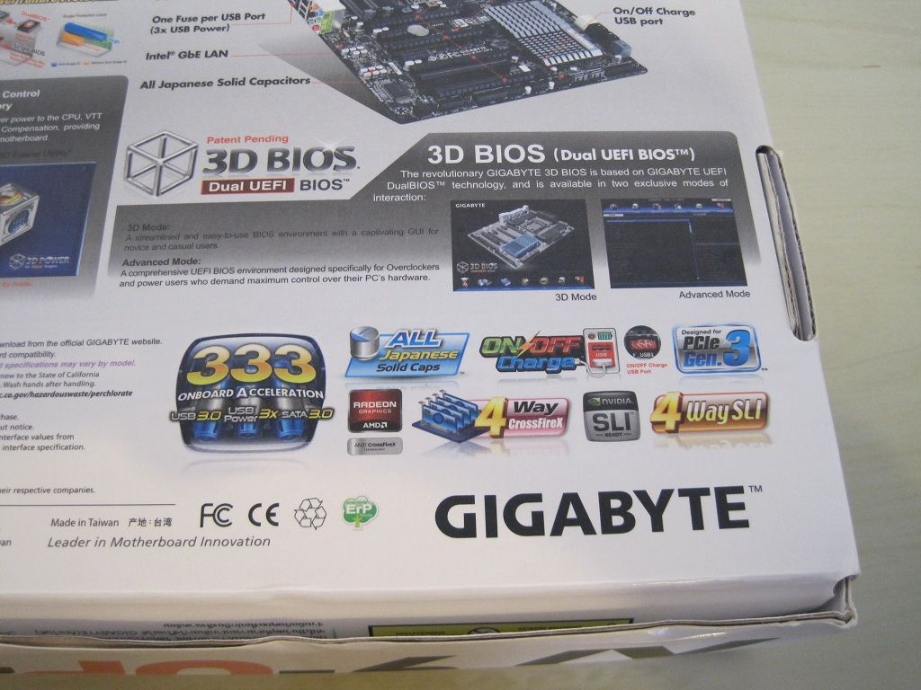
The specifications and features are explained as per previous motherboard boxes.
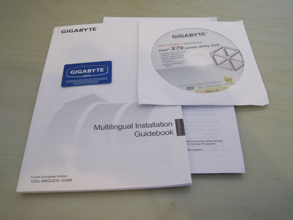
• Quick start guides, instruction manual.
• Driver CD.
• Case badge.
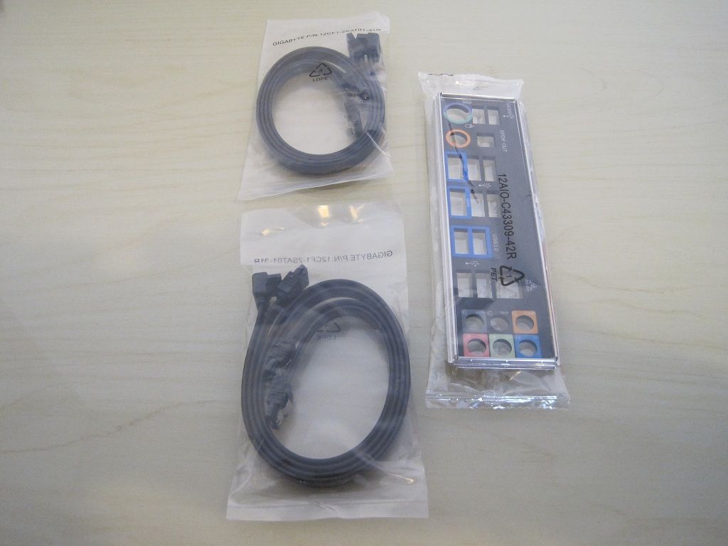
• I/O shield plate.
• Four SATAIII cables (two with 90° angle heads).
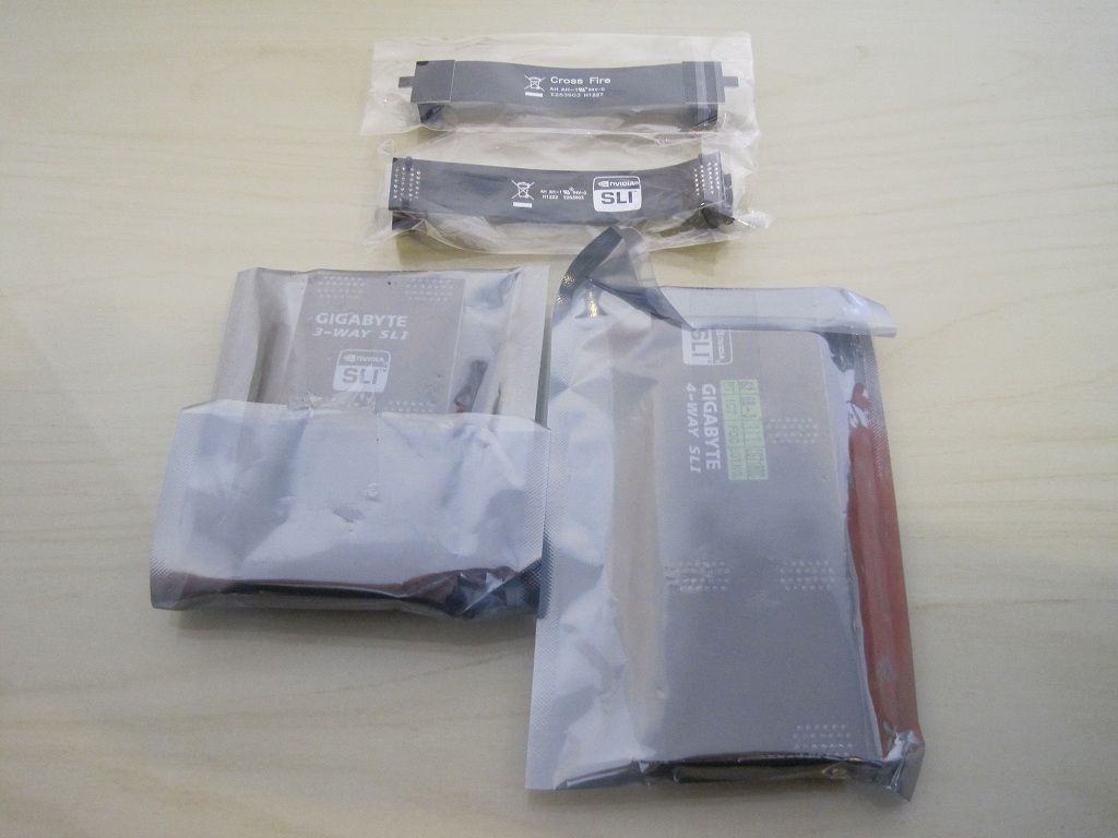
• 2 way Crossfire bridge.
• 2 way SLI bridge.
• 3 way SLI bridge.
• 4 way SLI bridge.
The board.
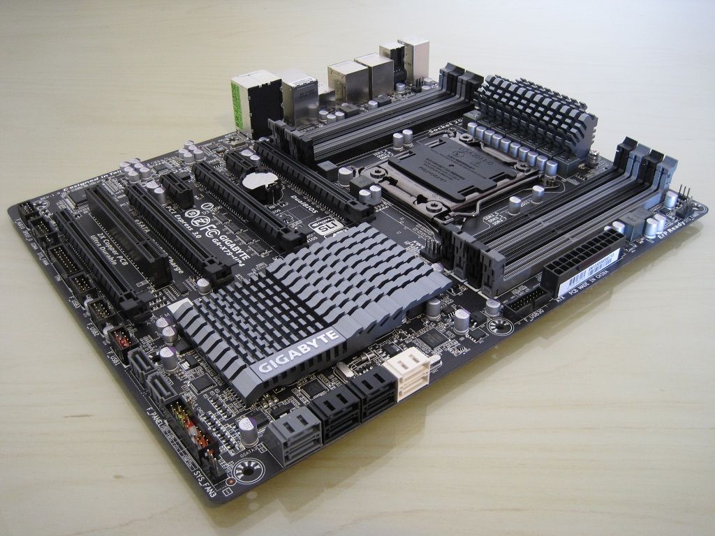
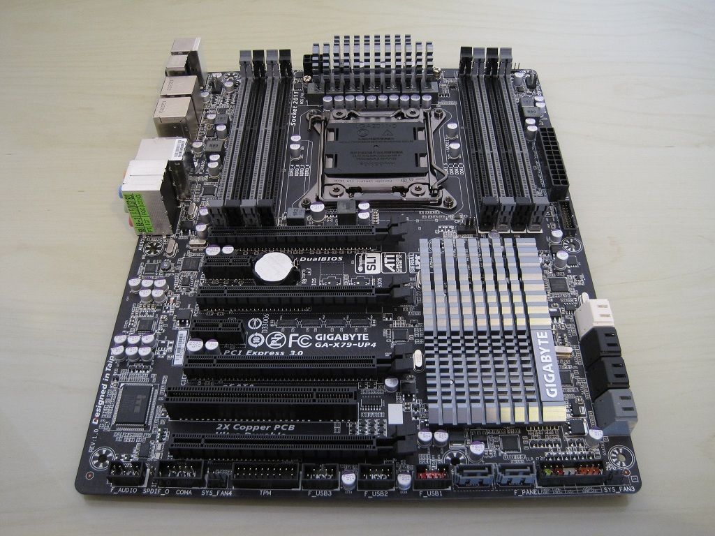
Stunning looking board, I really like the dark grey and black theme as it reminds me of my beloved GA-Z68XP-UD4
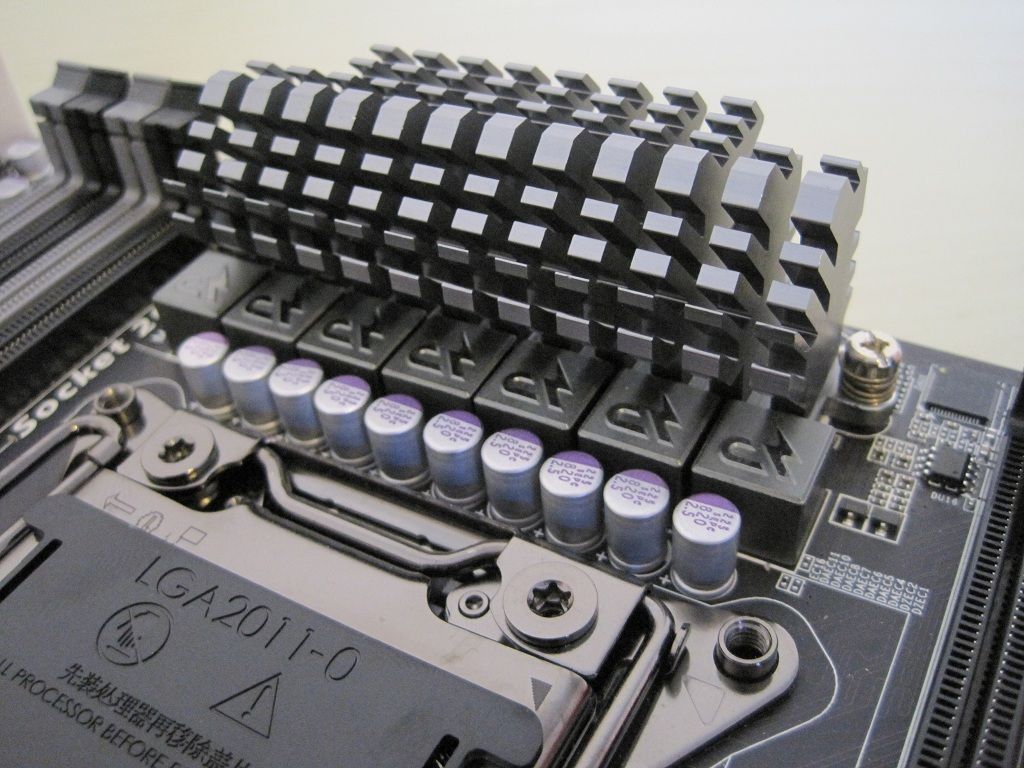
Under the heatsink are seven of the IR3550 PoweIRstages. There are 6 for the CPU with the extra one for the system agent.
In front of these and visible are Lightening-P chokes which are also rated at 60A each.
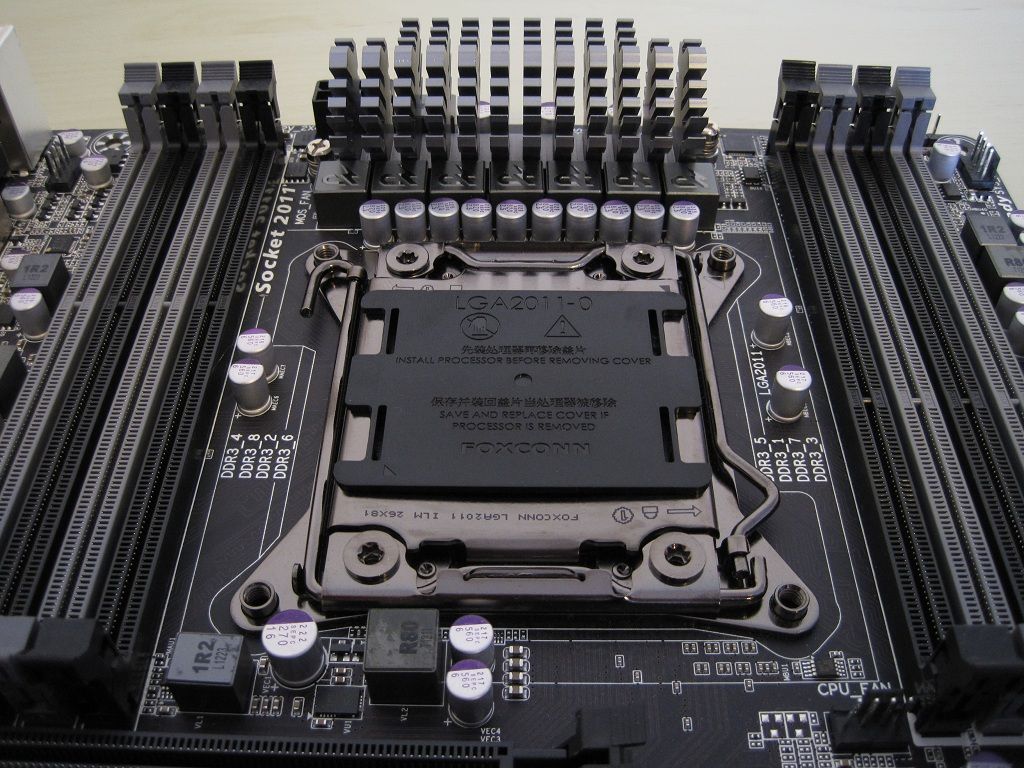
Eight DIMM slots and a CPU fan header, I wish there were two as most high-end heatsinks come with dual fans and you may not want to use "Y" adapters of a single header.
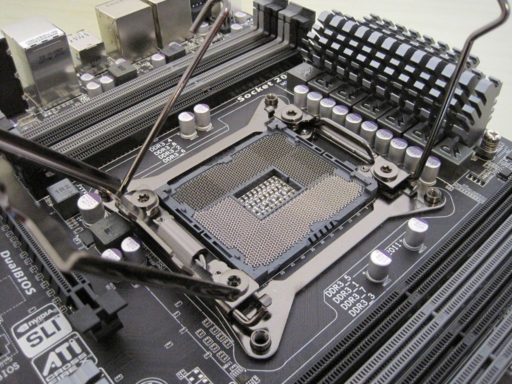
2011 individual pins are found in the CPU socket.
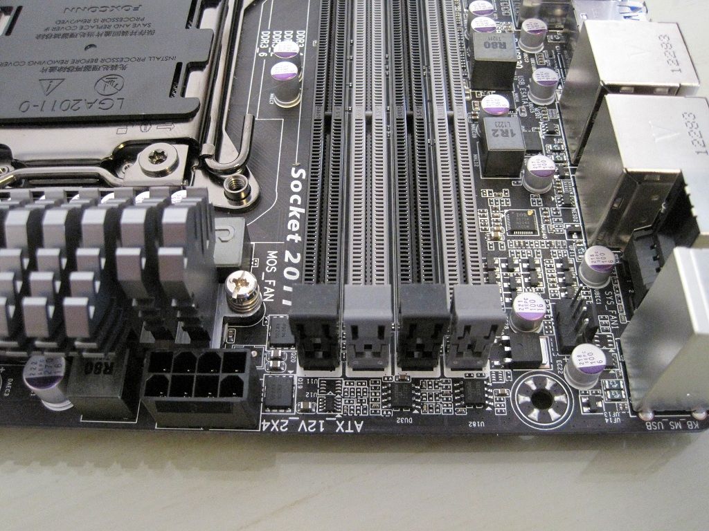
8pin ATX and a system fan header along the top edge.
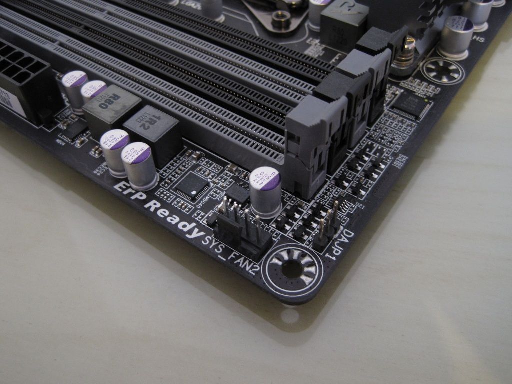
Another system fan header.
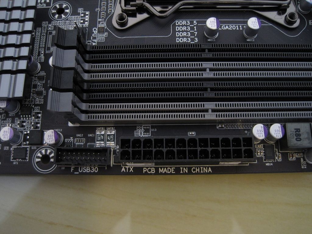
24 pin ATX and internal USB3.0 header.
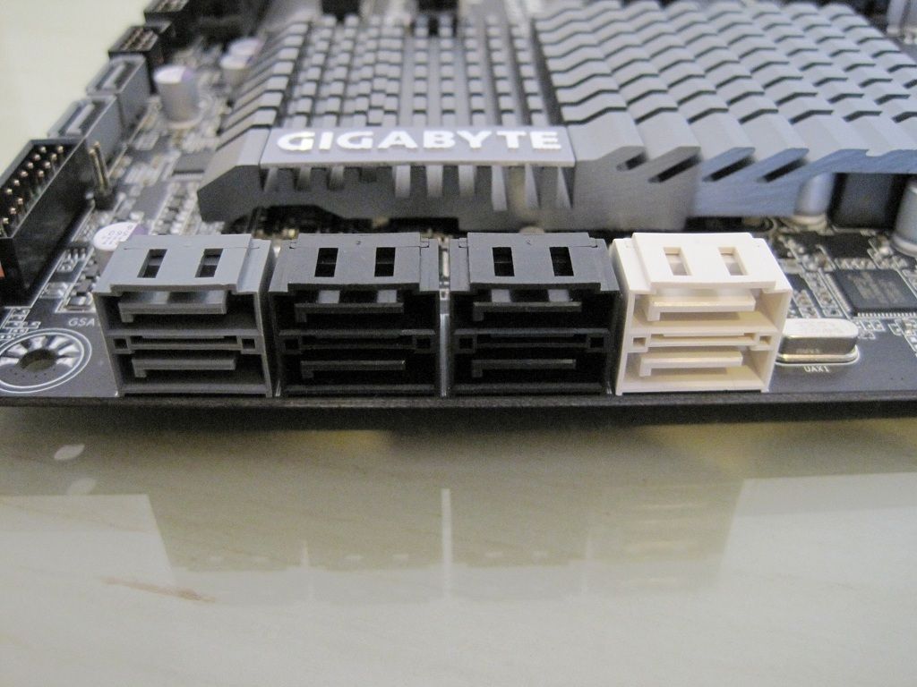
• 2 Intel SATAIII (white)
• 4 Intel SATAII (black)
• 2 Marvell SATAIII (grey)
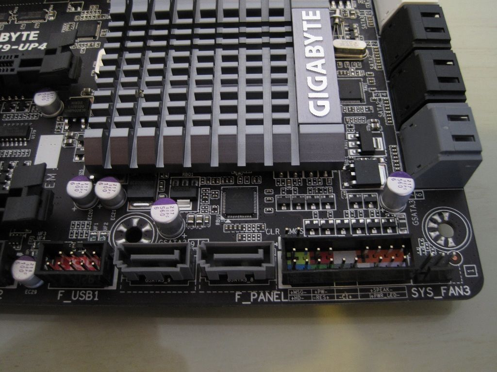
• System fan header
• Front panel connector
• 2X Marvell SATAIII ports.
• USB 2.0 3X power charge internal header.
The clearCMOS pins are hiding just above the front panel connector.
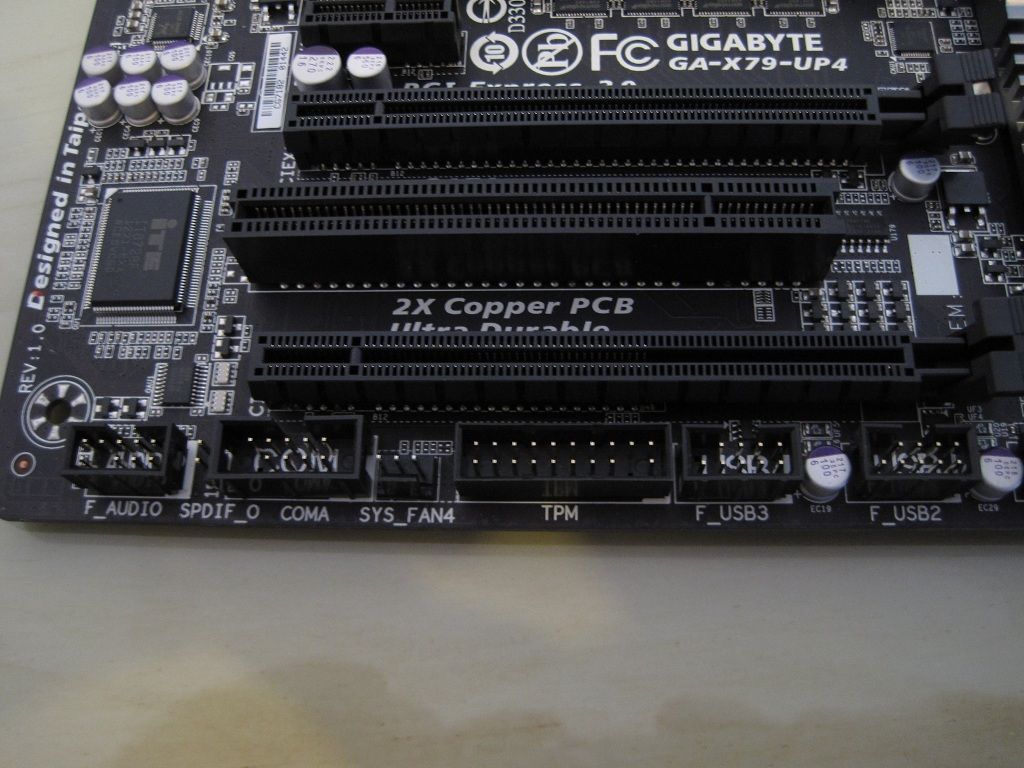
• 2X USB 2.0 internal headers.
• TPM (trusted platform module) header.
• System fan header.
• Serial port header.
• S/PDIF out header.
• Front panel audio header
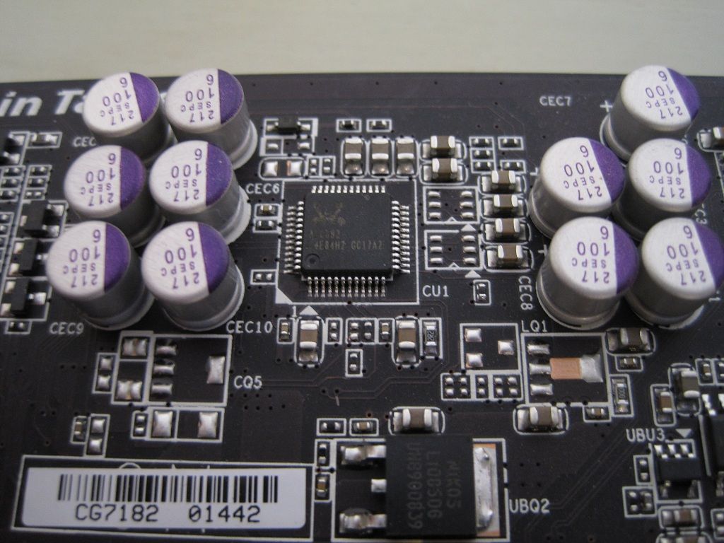
Realtek ALC892 audio chip, this is a very common sound chip used across a large range of boards, its adequate.
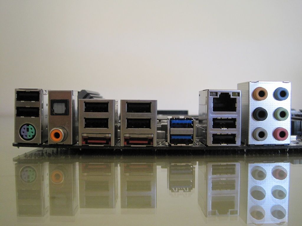
• 2X USB2.0 ports and PS/2 connector
• Optical/Coaxial audio out
• 2X USB2.0 and eSATA 6Gb/s
• 2X USB2.0 and eSATA 6Gb/s
• 2X USB3.0
• Ethernet (Intel 10/100/1000 Mbit)
• 7.1 audio out (Center/Subwoofer Speaker Out/Rear Speaker Out/Side Speaker Out/Line In/Line Out/Microphone)
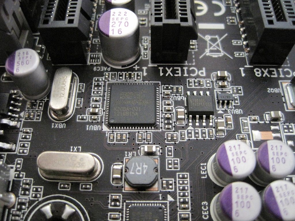
This is a Fresco FL1009 chip, there are two on the board and they provide the USB 3.0 rear and front panel connection.
Expansion slots.
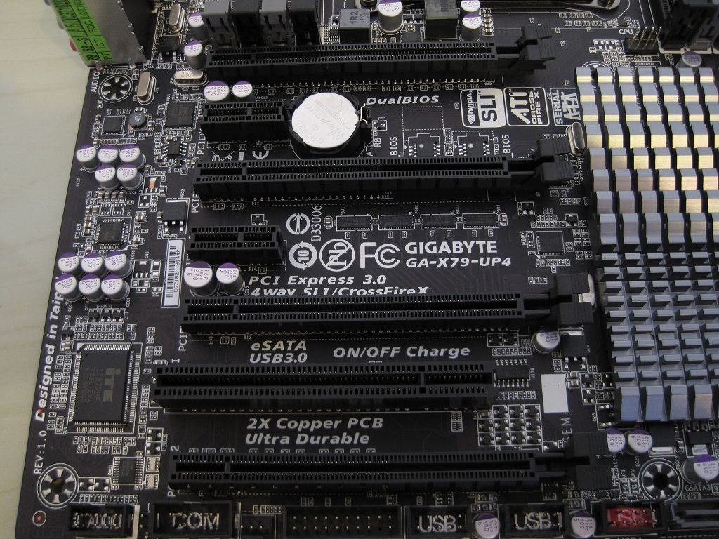
A good range of PCI-E expansion slots with one legacy PCI slot present for older expansion cards.
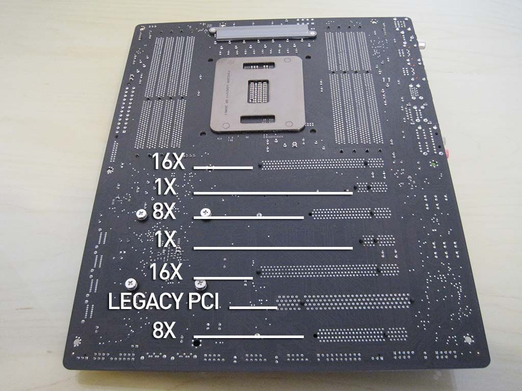
This shows how the PCI lanes are divided between the slots.
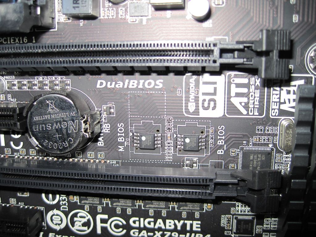
The DualBIOS chips.
Having DualBIOS is brilliant as it makes it impossible to kill the motherboard should you have a bad flash which would turn most other boards into nothing more then a paper weight.
What might cause a BIOS Failure?
• Power shut down during BIOS update process
• Improper Overclocking settings
• Virus attacks
• Hardware Failure
The board will boot from the backup BIOS and you can even flash the backup BIOS to the main one to restore.
BIOS.
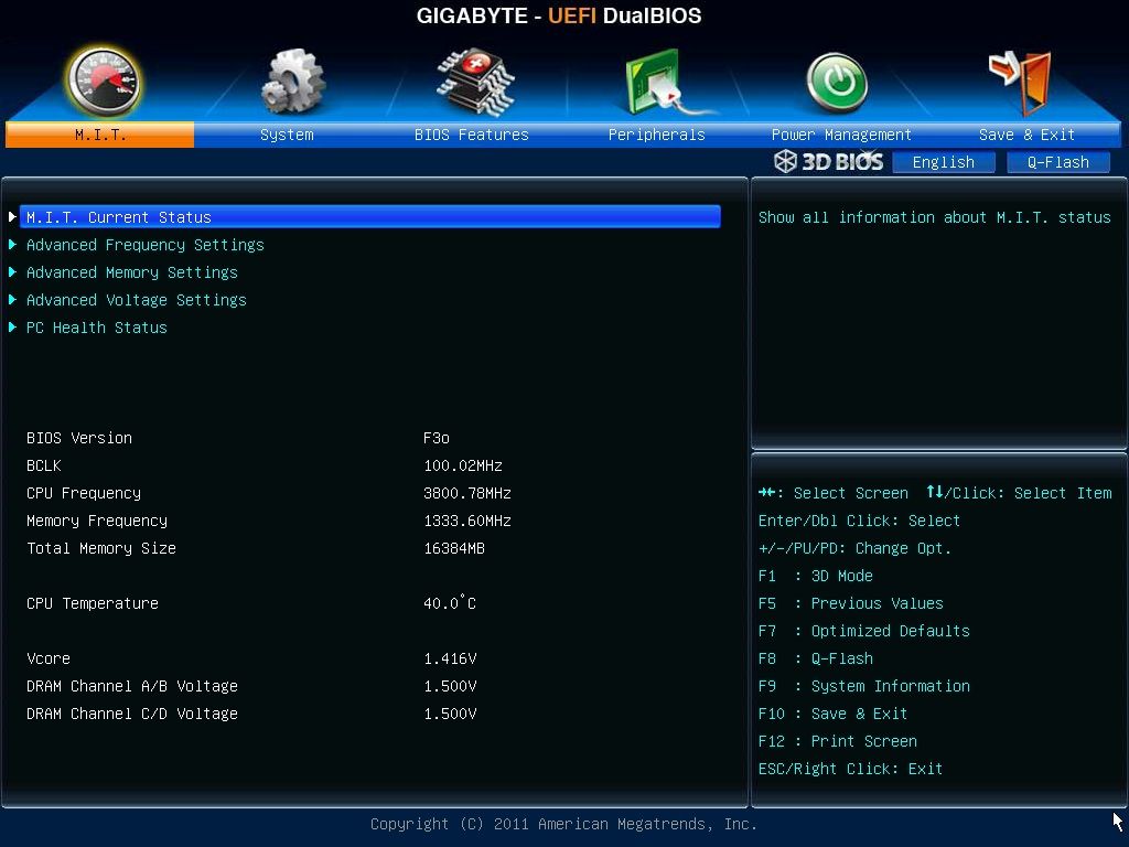
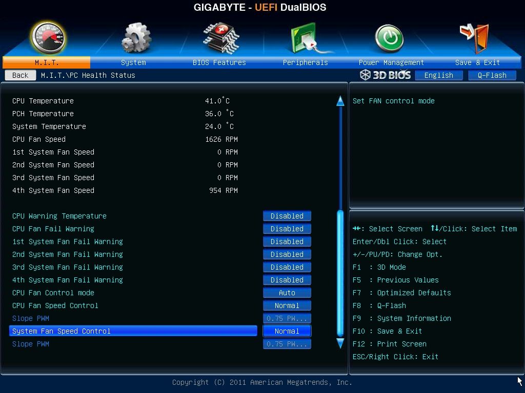
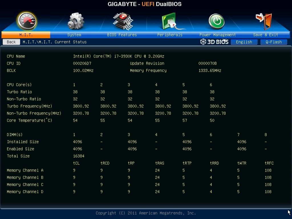
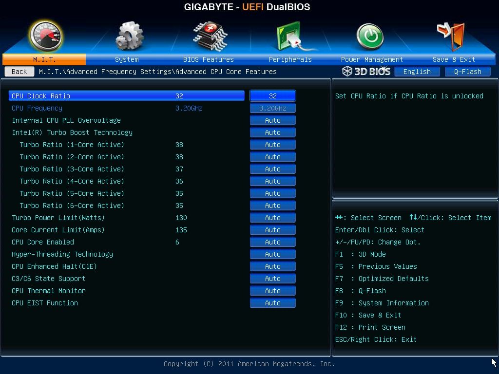
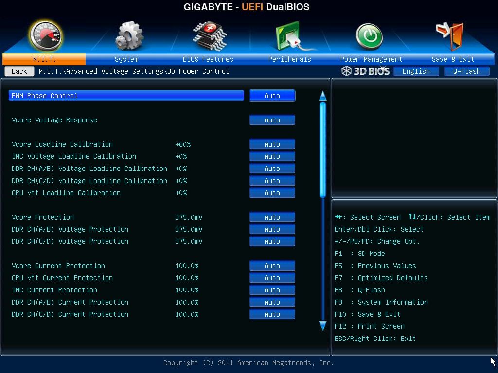
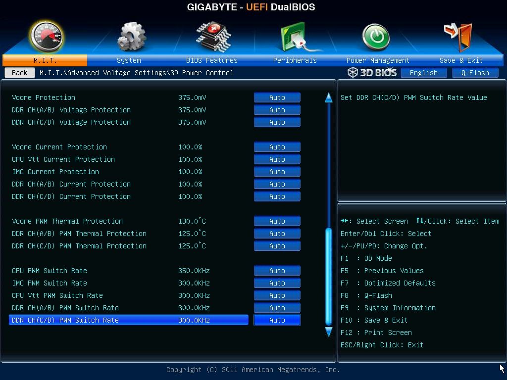
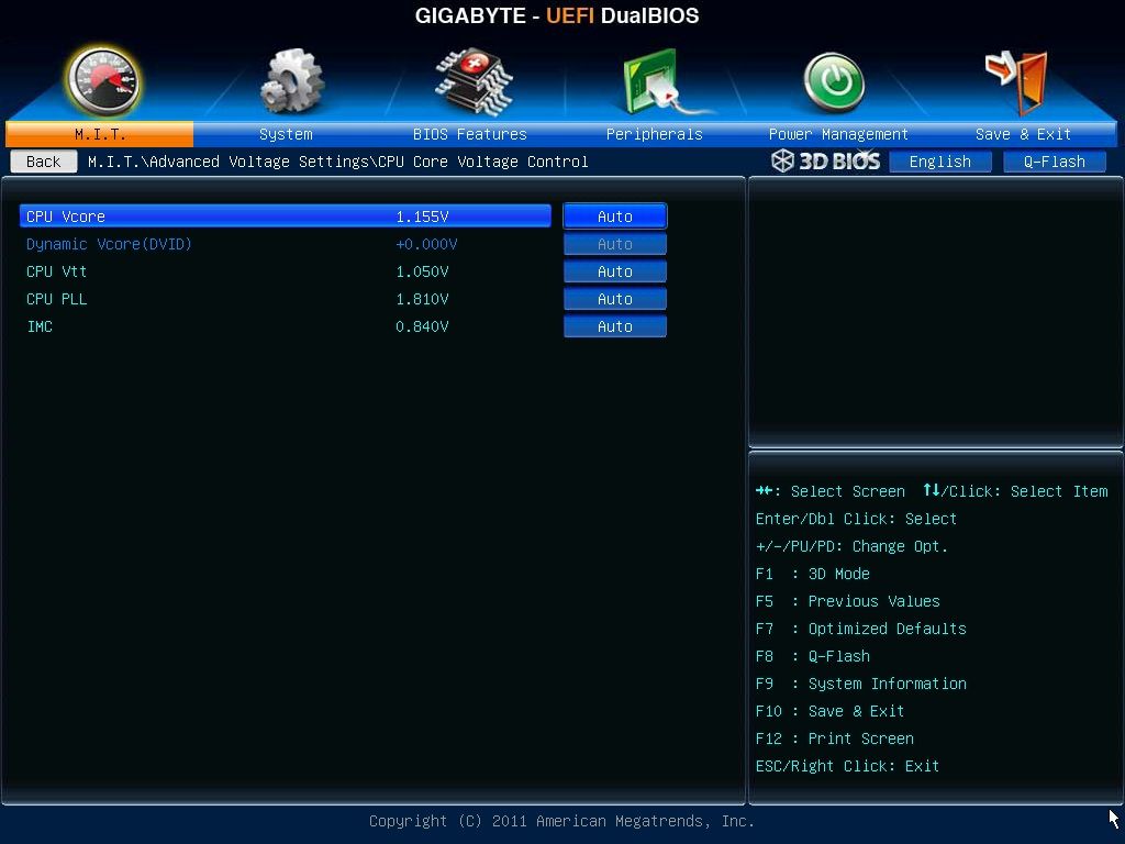
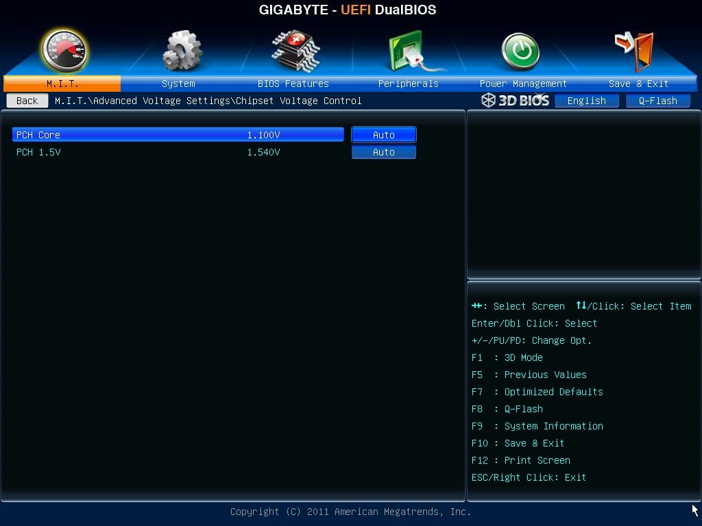
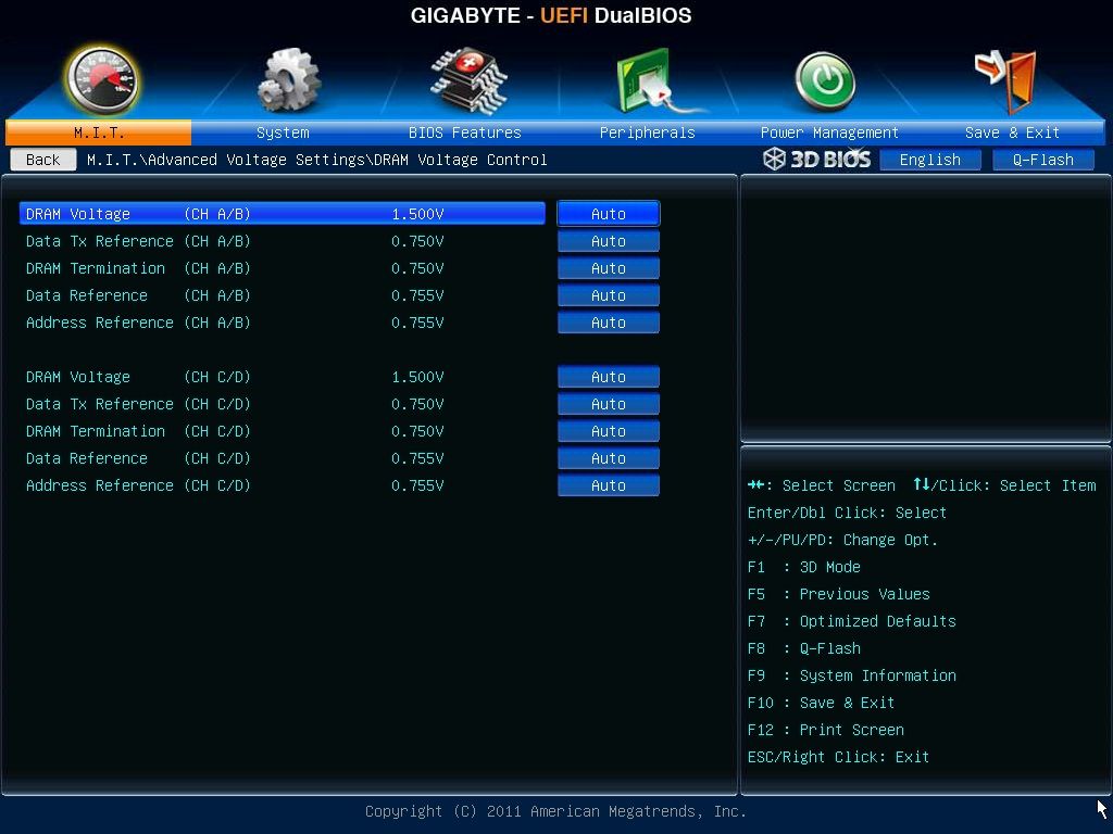
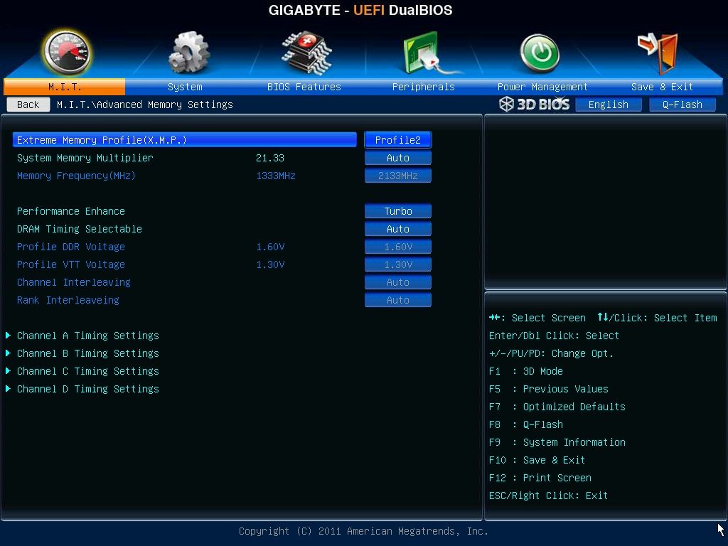
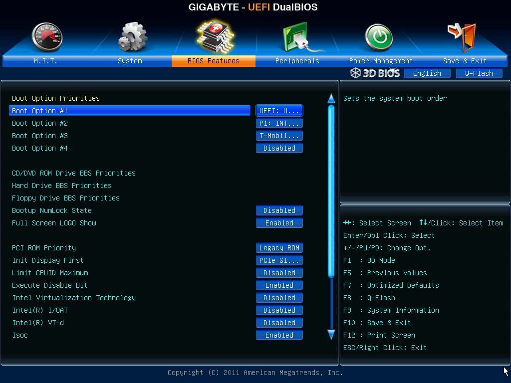
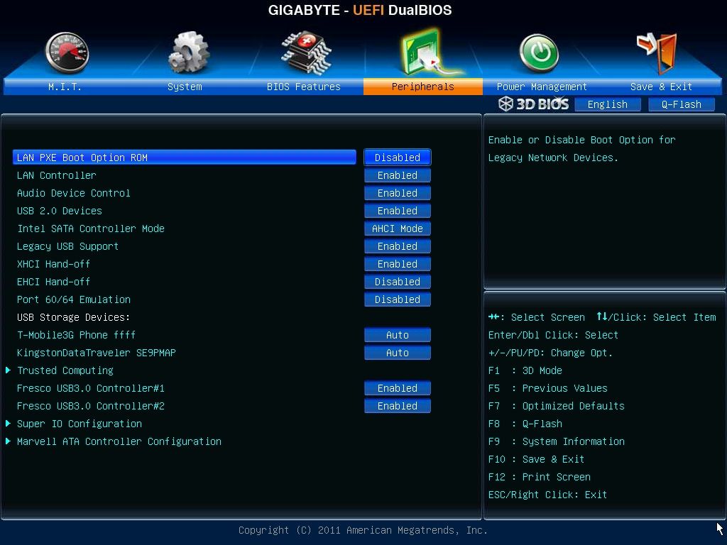
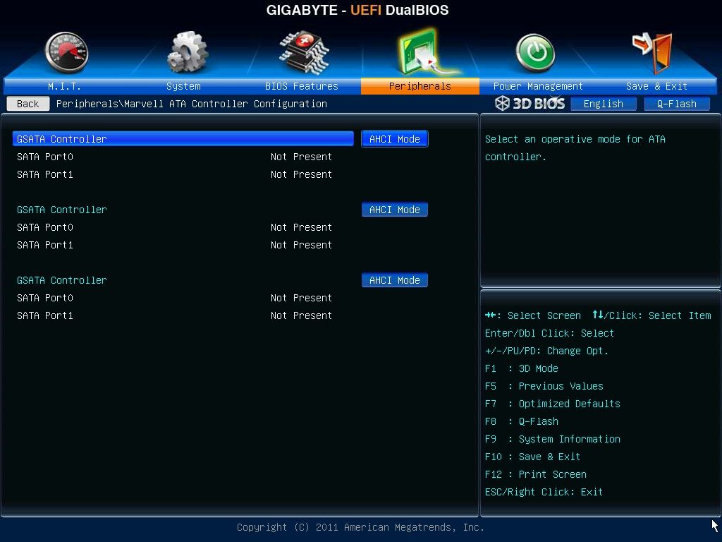
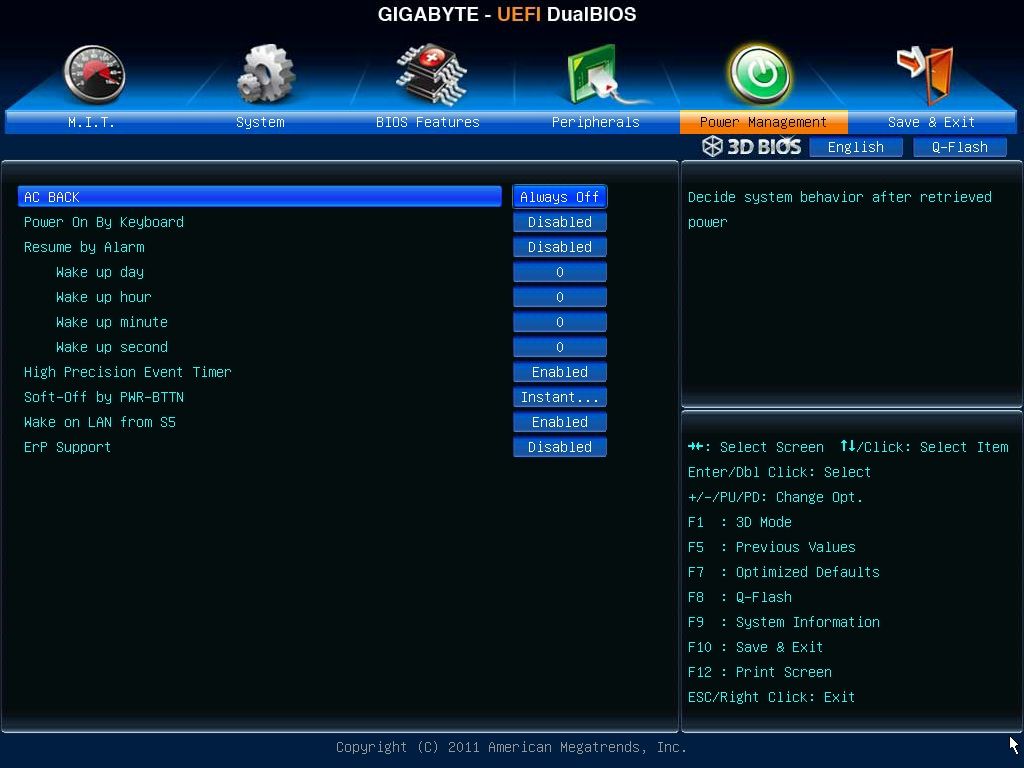
An almost confusing set of options and adjustment, there is also 3D BIOS mode available at a click of a button.
Bundle software.
• All necessary drivers
• 3D Power Utility
• Norton Internet security
• ON/OFF charge
• Easytune6
• @BIOS
• Smart recovery 2
• DMI Viewer
• Face-Wizard
• Q-share
• Update manager
• Acrobat Reader
• WinZip
• AIWI Game 64bit
• Splashtop Streamer
• 3TB+ unlock
Benchmarking.
Intel SATAIII performance.

A little bit slower than both Z77 motherboards when it comes to the read speeds, but nothing to be concerned about.
Overclocking.
*You may experience different results at these settings and I wouldn't tell anyone to try the same settings as me but there are many guides about that will help you with your overclock and no two motherboards or CPU’s are the same (silicon lottery)
My biggest piece of advice is to get a newer BIOS flashed onto the board than F2, the later BetaBIOSes have vastly improved the Vdroop reported,
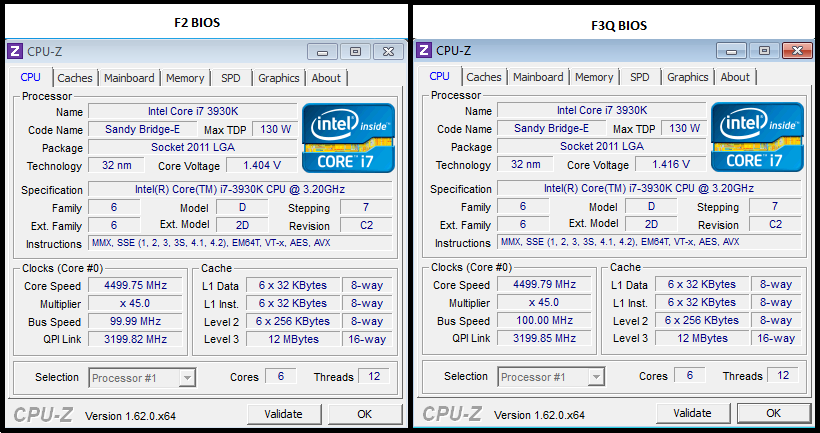
Overclocking with the X79-UP4 it was very easy to achieve a simple 4.5Ghz which took me just minutes to get 100% stable.
All that this required was,
Clock ratios = 45X
Disable C1E/EIST etc
Vcore =1.43v
Vcore Voltage response = Fast
Vcore Loadline Calibration = Turbo
http://valid.canardpc.com/2642916
4.7Ghz was then next and this required just an extra .01v added to the Vcore (1.44V in BIOS) and setting the ratios to 47X
http://valid.canardpc.com/2642975
4.8Ghz requires good cooling as the thermal limit (TJmax) is 91C for the CPU, 4.8Ghz again required another increase in Vcore taking it to 1.465v.
http://valid.canardpc.com/show_oc.php?id=2594983
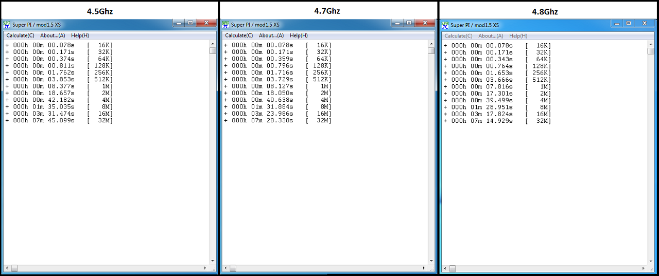
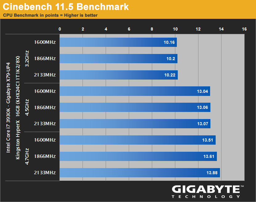
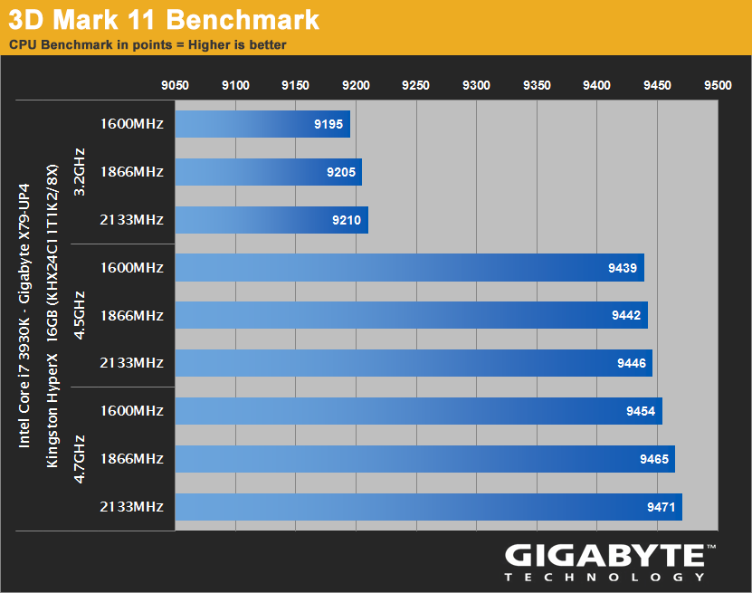
There is of course more you can do to increase the overall performance such as increasing the RAM speed and trying to tighten the memory timings, then there is also the ability to change the BCLK strap which is another route to gaining more performance from the platform.
Benchmark results.
Cinebench.
3DMark11.
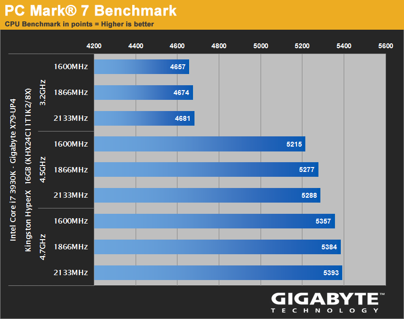
PCMark07.
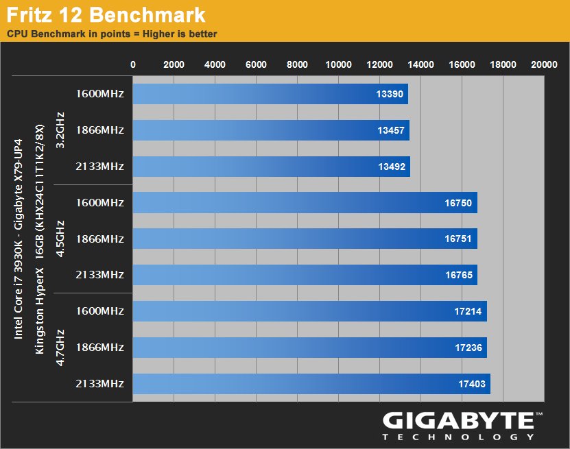
Fritz.
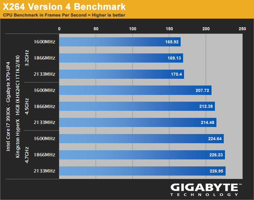
x264 ver4.0.
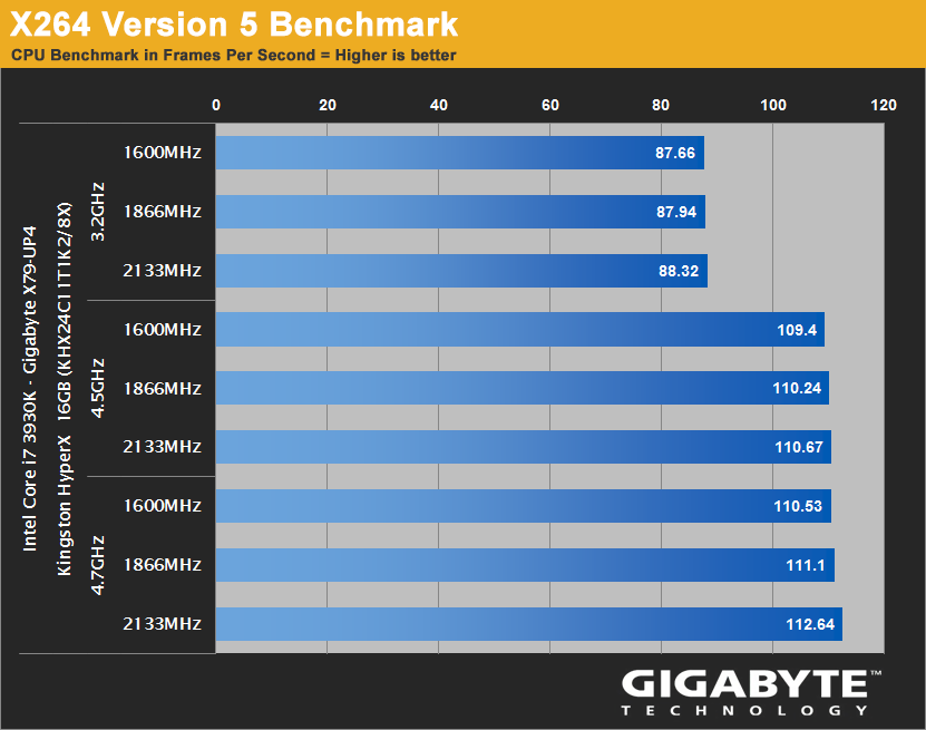
x264 ver5.0.
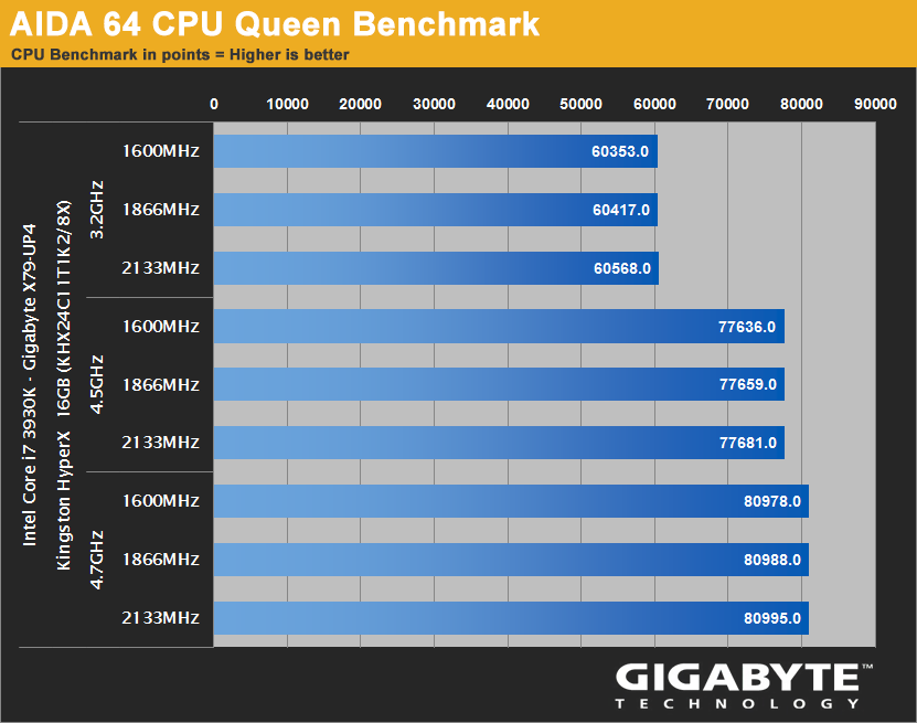
Aida 64 CPU Queen.
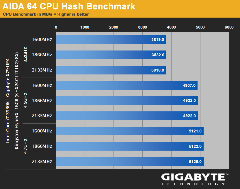
Aida 64 CPU Hash.
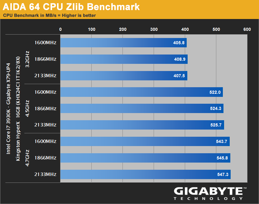
Aida 64 CPU Zlib.
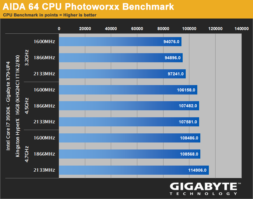
Aida 64 CPU Photoworxx.
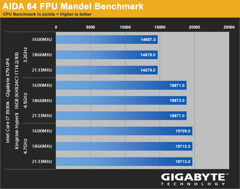
Aida 64 FPU Mandel.
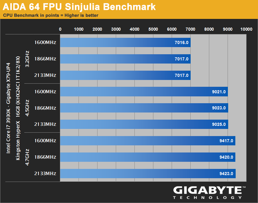
Aida 64 FPU Sinjulia.
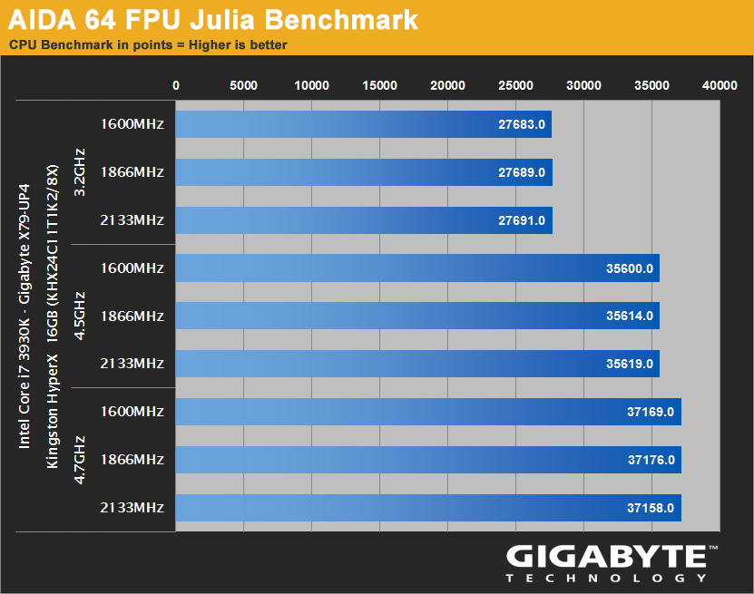
Aida 64 FPU Julia.
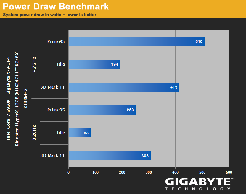
Power usage.
For this test I have bought an energy monitor, this sits between the PSU cable coming from the base unit and the socket.
It can report Volts/Amps/Watts and KWH usage.
The below results were the peak I witnessed being reported by the device during Idle running 3Dmark11 and running Prime95.
Conclusion.
This is my first foray into the X79 platform so I don't actually have any other X79 boards to compare it to as I have with Z77, My experiences are that If you are serious about needing a platform that can crunch data hard and you are the sort of end-user that is more than the "hobby" video editor/power user, then this platform with its selection of powerful CPU's available is for you.
Getting back to this particular motherboard, I was disappointed by the F2 BIOS that it came with out of the box as I found the Vdroop reported via CPU-Z to be poor to what I expected.
This Vdroop though has certainly been improved with anyone of the newer BetaBIOSes available either at Tweaktown or indeed there is one available direct at the Gigabyte website.
The X79-UP4 is well made, looks fantastic with its dark colour scheme and was easy to use everyday and overclock with, I found 4.7Ghz to be perfect for me and a safe 24/7 setting for my uses
The board has great expansion with a full eight dimm slots meaning you can get 64GB easily installed (provided you have a suitable OS), good amounts of SATAII+III and USB3.0+2.0 ports.
Things I would like to see improved? two CPU fan headers and a second USB3.0 internal header would have been the icing on the cake.


Ocuk product page - http://www.overclockers.co.uk/showproduct.php?prodid=MB-414-GI&groupid=701&catid=5&subcat=2174
Gigabyte homepage - http://uk.gigabyte.com/products/product-page.aspx?pid=4288#ov
The X79 chipset from Intel is aimed at the high-end consumer market and is designed for power users who use their PC's for more than just gaming and some simple video editing etc, If you do a lot of heavy workload on your PC such as editing/rendering then this is a platform you maybe interested in as the CPU's available for it consist of not only quad core processors but also Hex core and even eight core CPU's such as Xeons (provided the board supports it). Hyperthreading is also present on nearly all the CPU's compatible with X79 motherboards.
The GA-X79-UP4 CPU support list can be found here - http://uk.gigabyte.com/support-downloads/cpu-support-popup.aspx?pid=4288 -you will see a few Xeon CPU's listed as well, some of those are eight core variants such as the Xeon E5-2680 which does include Hyperthreading making a total number of 16 threads.
As the board features Ultra Durable 5 it has IR3550 PoweIRstages powering the CPU also, theses chips are rated at 60A each yet remain cool and efficient. They have won a few industry product awards also


Boards with "UP" in the model name will have Ultra Durable5 and these PoweIRstages.
Packaging and accessories.


The specifications and features are explained as per previous motherboard boxes.

• Quick start guides, instruction manual.
• Driver CD.
• Case badge.

• I/O shield plate.
• Four SATAIII cables (two with 90° angle heads).

• 2 way Crossfire bridge.
• 2 way SLI bridge.
• 3 way SLI bridge.
• 4 way SLI bridge.
The board.


Stunning looking board, I really like the dark grey and black theme as it reminds me of my beloved GA-Z68XP-UD4

Under the heatsink are seven of the IR3550 PoweIRstages. There are 6 for the CPU with the extra one for the system agent.
In front of these and visible are Lightening-P chokes which are also rated at 60A each.

Eight DIMM slots and a CPU fan header, I wish there were two as most high-end heatsinks come with dual fans and you may not want to use "Y" adapters of a single header.

2011 individual pins are found in the CPU socket.

8pin ATX and a system fan header along the top edge.

Another system fan header.

24 pin ATX and internal USB3.0 header.

• 2 Intel SATAIII (white)
• 4 Intel SATAII (black)
• 2 Marvell SATAIII (grey)

• System fan header
• Front panel connector
• 2X Marvell SATAIII ports.
• USB 2.0 3X power charge internal header.
The clearCMOS pins are hiding just above the front panel connector.

• 2X USB 2.0 internal headers.
• TPM (trusted platform module) header.
• System fan header.
• Serial port header.
• S/PDIF out header.
• Front panel audio header

Realtek ALC892 audio chip, this is a very common sound chip used across a large range of boards, its adequate.

• 2X USB2.0 ports and PS/2 connector
• Optical/Coaxial audio out
• 2X USB2.0 and eSATA 6Gb/s
• 2X USB2.0 and eSATA 6Gb/s
• 2X USB3.0
• Ethernet (Intel 10/100/1000 Mbit)
• 7.1 audio out (Center/Subwoofer Speaker Out/Rear Speaker Out/Side Speaker Out/Line In/Line Out/Microphone)

This is a Fresco FL1009 chip, there are two on the board and they provide the USB 3.0 rear and front panel connection.
Expansion slots.

A good range of PCI-E expansion slots with one legacy PCI slot present for older expansion cards.

This shows how the PCI lanes are divided between the slots.

The DualBIOS chips.
Having DualBIOS is brilliant as it makes it impossible to kill the motherboard should you have a bad flash which would turn most other boards into nothing more then a paper weight.
What might cause a BIOS Failure?
• Power shut down during BIOS update process
• Improper Overclocking settings
• Virus attacks
• Hardware Failure
The board will boot from the backup BIOS and you can even flash the backup BIOS to the main one to restore.
BIOS.


An almost confusing set of options and adjustment, there is also 3D BIOS mode available at a click of a button.
Bundle software.
• All necessary drivers
• 3D Power Utility
• Norton Internet security
• ON/OFF charge
• Easytune6
• @BIOS
• Smart recovery 2
• DMI Viewer
• Face-Wizard
• Q-share
• Update manager
• Acrobat Reader
• WinZip
• AIWI Game 64bit
• Splashtop Streamer
• 3TB+ unlock
Benchmarking.
Test setup,
• GA-X79-UP4
• i7 3930K
• Kingston HyperX RAM (4X4GB)
• Intel 520 series 240GB SSD
• Gigabyte GTX670
Intel SATAIII performance.

A little bit slower than both Z77 motherboards when it comes to the read speeds, but nothing to be concerned about.
Overclocking.
*You may experience different results at these settings and I wouldn't tell anyone to try the same settings as me but there are many guides about that will help you with your overclock and no two motherboards or CPU’s are the same (silicon lottery)
My biggest piece of advice is to get a newer BIOS flashed onto the board than F2, the later BetaBIOSes have vastly improved the Vdroop reported,

Overclocking with the X79-UP4 it was very easy to achieve a simple 4.5Ghz which took me just minutes to get 100% stable.
All that this required was,
Clock ratios = 45X
Disable C1E/EIST etc
Vcore =1.43v
Vcore Voltage response = Fast
Vcore Loadline Calibration = Turbo
http://valid.canardpc.com/2642916
4.7Ghz was then next and this required just an extra .01v added to the Vcore (1.44V in BIOS) and setting the ratios to 47X
http://valid.canardpc.com/2642975
4.8Ghz requires good cooling as the thermal limit (TJmax) is 91C for the CPU, 4.8Ghz again required another increase in Vcore taking it to 1.465v.
http://valid.canardpc.com/show_oc.php?id=2594983

There is of course more you can do to increase the overall performance such as increasing the RAM speed and trying to tighten the memory timings, then there is also the ability to change the BCLK strap which is another route to gaining more performance from the platform.
Benchmark results.
Cinebench.

3DMark11.

PCMark07.

Fritz.

x264 ver4.0.

x264 ver5.0.

Aida 64 CPU Queen.

Aida 64 CPU Hash.

Aida 64 CPU Zlib.

Aida 64 CPU Photoworxx.

Aida 64 FPU Mandel.

Aida 64 FPU Sinjulia.

Aida 64 FPU Julia.

Power usage.
For this test I have bought an energy monitor, this sits between the PSU cable coming from the base unit and the socket.
It can report Volts/Amps/Watts and KWH usage.
The below results were the peak I witnessed being reported by the device during Idle running 3Dmark11 and running Prime95.

Conclusion.
This is my first foray into the X79 platform so I don't actually have any other X79 boards to compare it to as I have with Z77, My experiences are that If you are serious about needing a platform that can crunch data hard and you are the sort of end-user that is more than the "hobby" video editor/power user, then this platform with its selection of powerful CPU's available is for you.
Getting back to this particular motherboard, I was disappointed by the F2 BIOS that it came with out of the box as I found the Vdroop reported via CPU-Z to be poor to what I expected.
This Vdroop though has certainly been improved with anyone of the newer BetaBIOSes available either at Tweaktown or indeed there is one available direct at the Gigabyte website.
The X79-UP4 is well made, looks fantastic with its dark colour scheme and was easy to use everyday and overclock with, I found 4.7Ghz to be perfect for me and a safe 24/7 setting for my uses
The board has great expansion with a full eight dimm slots meaning you can get 64GB easily installed (provided you have a suitable OS), good amounts of SATAII+III and USB3.0+2.0 ports.
Things I would like to see improved? two CPU fan headers and a second USB3.0 internal header would have been the icing on the cake.


 considering buying this board for my work PC