Dell XPS 700 case - BTX to ATX conversion

Associate
Joined
21 Jul 2009
Posts
28
Location
Swindon
Honda Mugen PC Case - Dell XPS 700 - BTX to ATX conversion

This is my first project log and case conversion ever, so probably won't be all perfect. The first mistake I know I've already made was not taking pictures from the start and before I actually started the conversion.

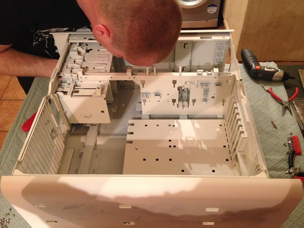
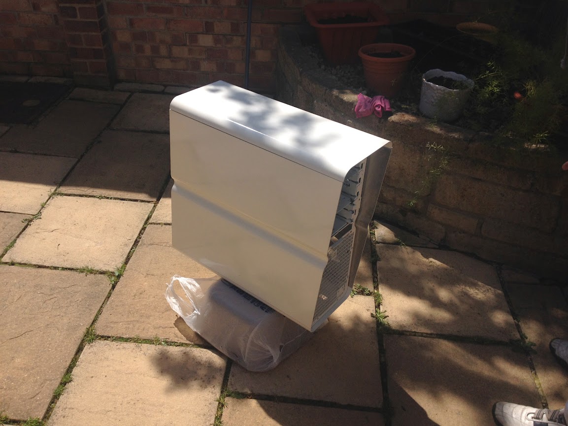
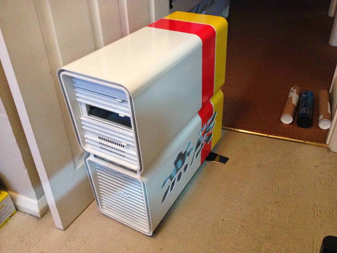
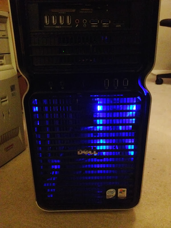
So the story is I got a XPS 700 case as a freebie, only to realise when I opened it up it's a BTX case. Having done some research and checked few other conversion threads, I decided to give it a go, since I really liked this case. And it was much better than one I had at that time.
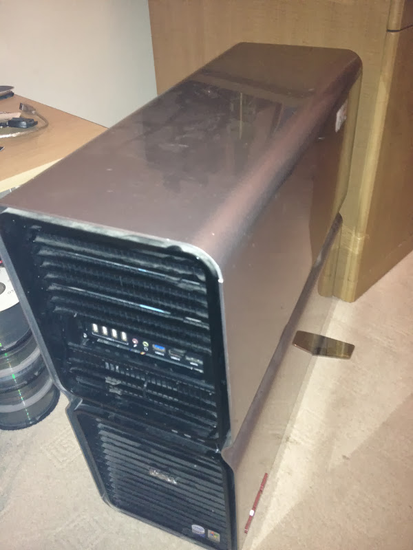
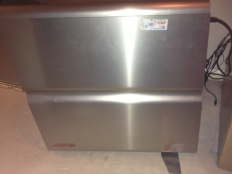
Old case
IMAGE_D21DFCB3-29C0-43C8-8645-6D70D4CF6123.JPG


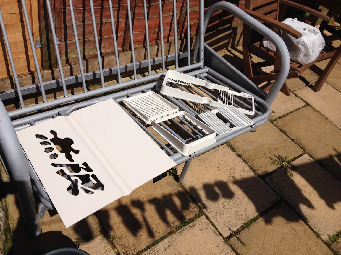
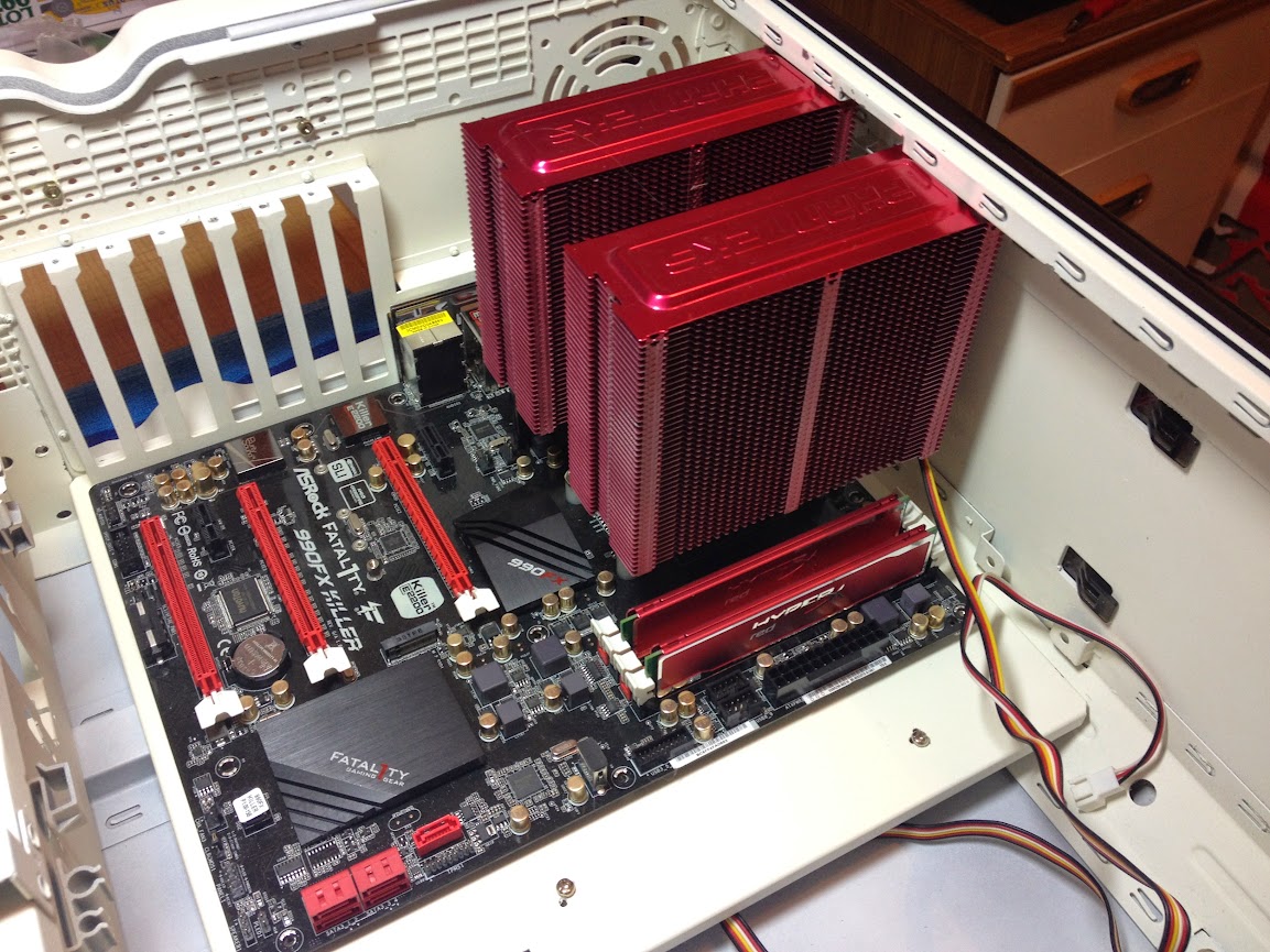
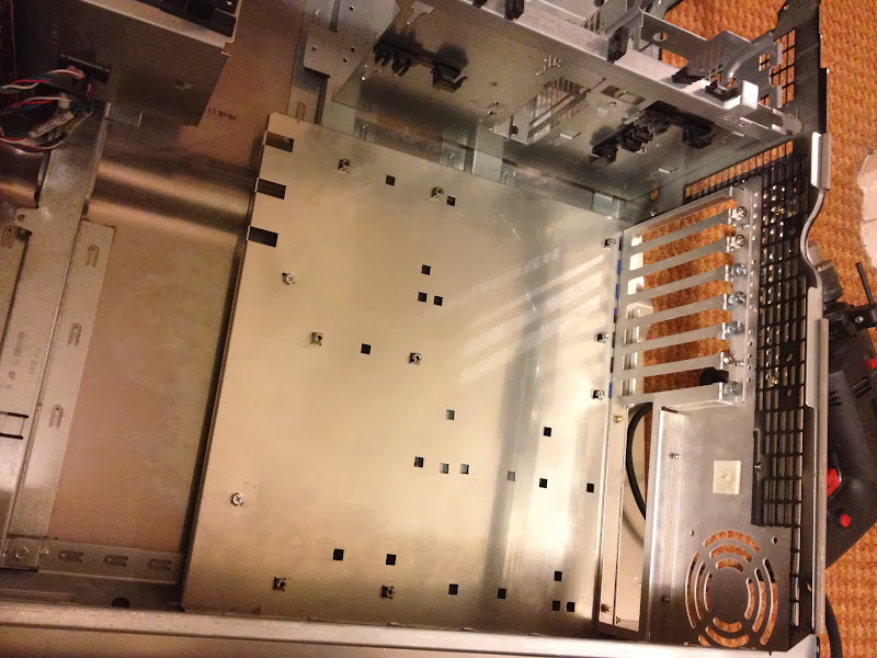
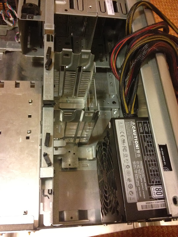
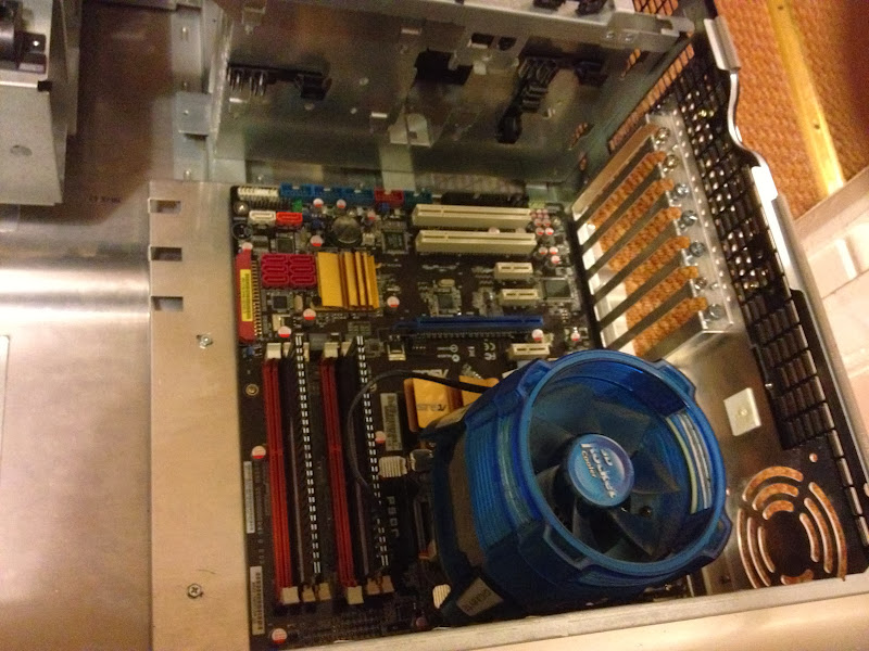
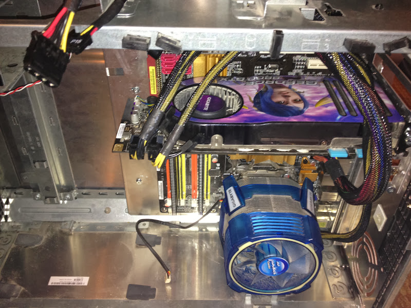
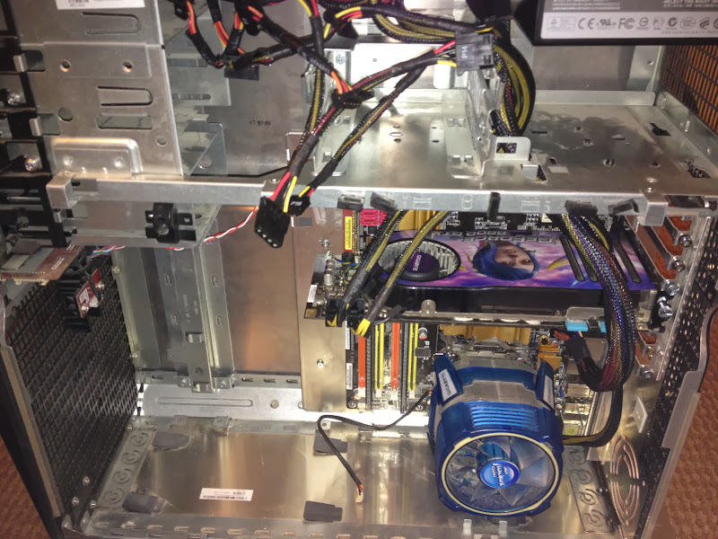
Started off by getting a Lian-Li PC60 Motherboard Tray with back panel. Then took all the bits out of the XPS case in preparation. At this point the project got stuck for good few weeks, as it involved cutting out a large portion of the back of the case, to accommodate for the inverted expansion cards slots.

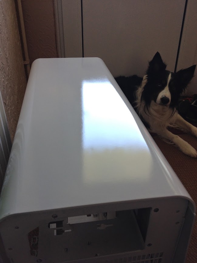
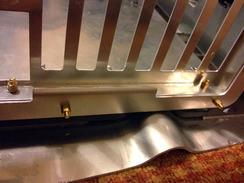
So when I finally got cutting it involved some drilling to get rid of the rivets holding the back panel, then cutting off the metal pieces that were in the way of the Lian-Li tray.

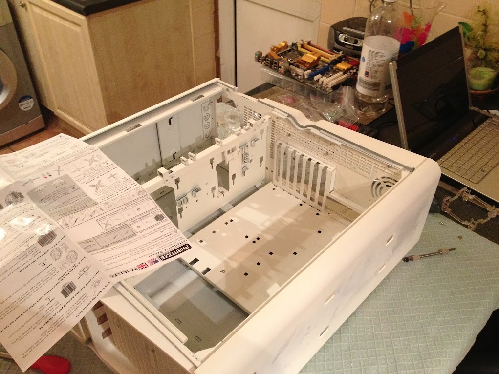
Before I fitted the Lian-Li tray, that had to be drilled and taken apart as well, as it just would not go in as one piece. Once in place, I used some screws and standoffs to join it back together.

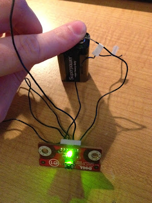
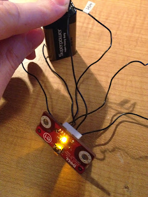
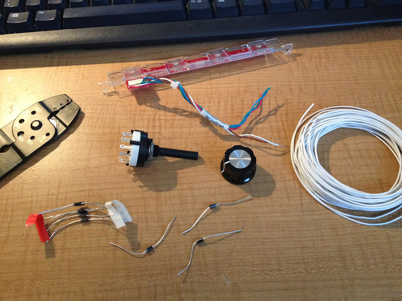
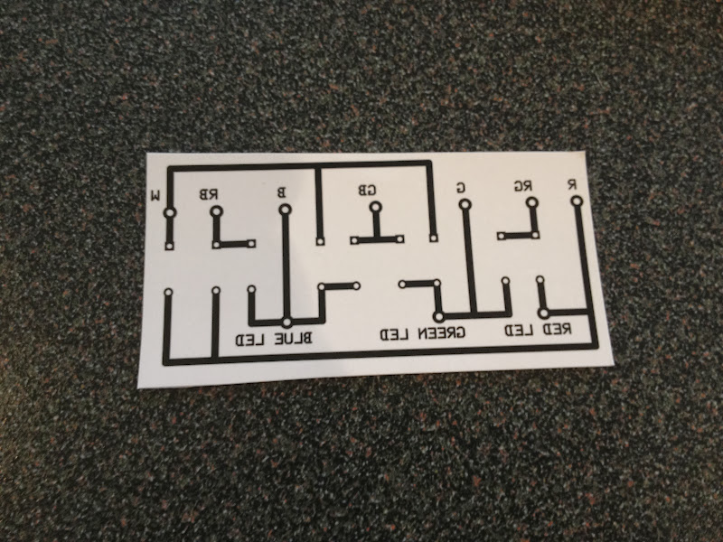
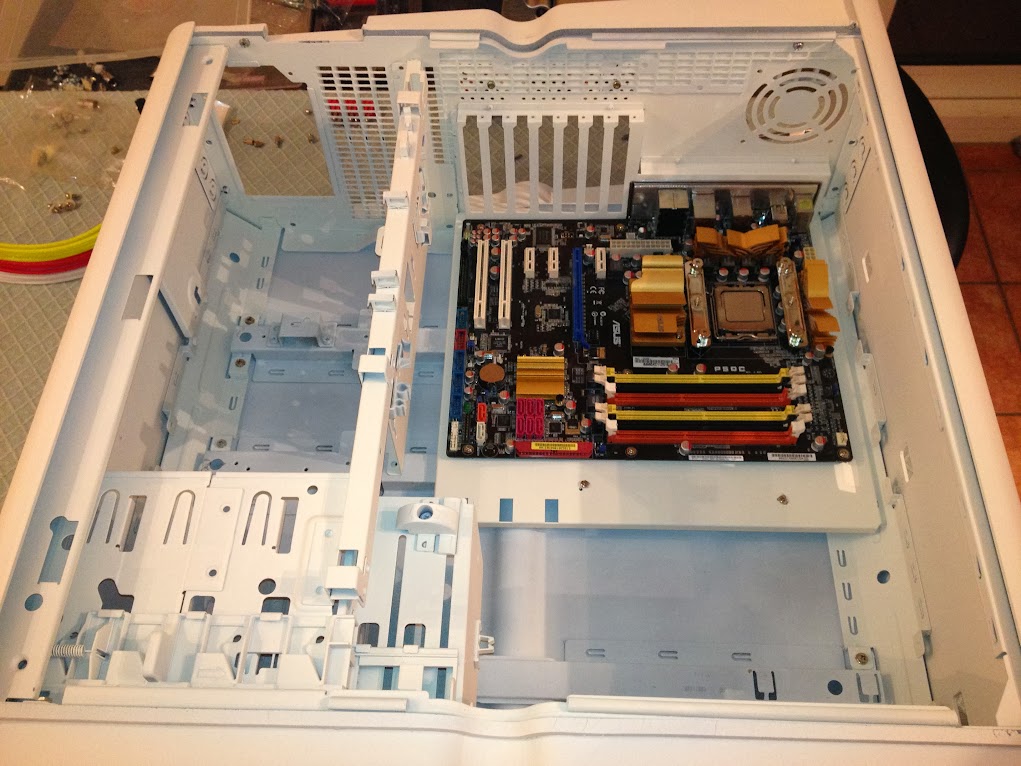
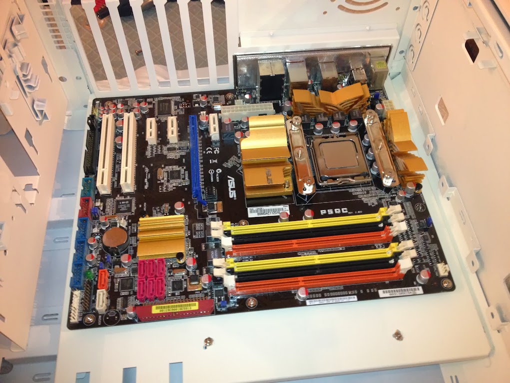
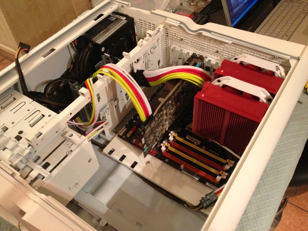
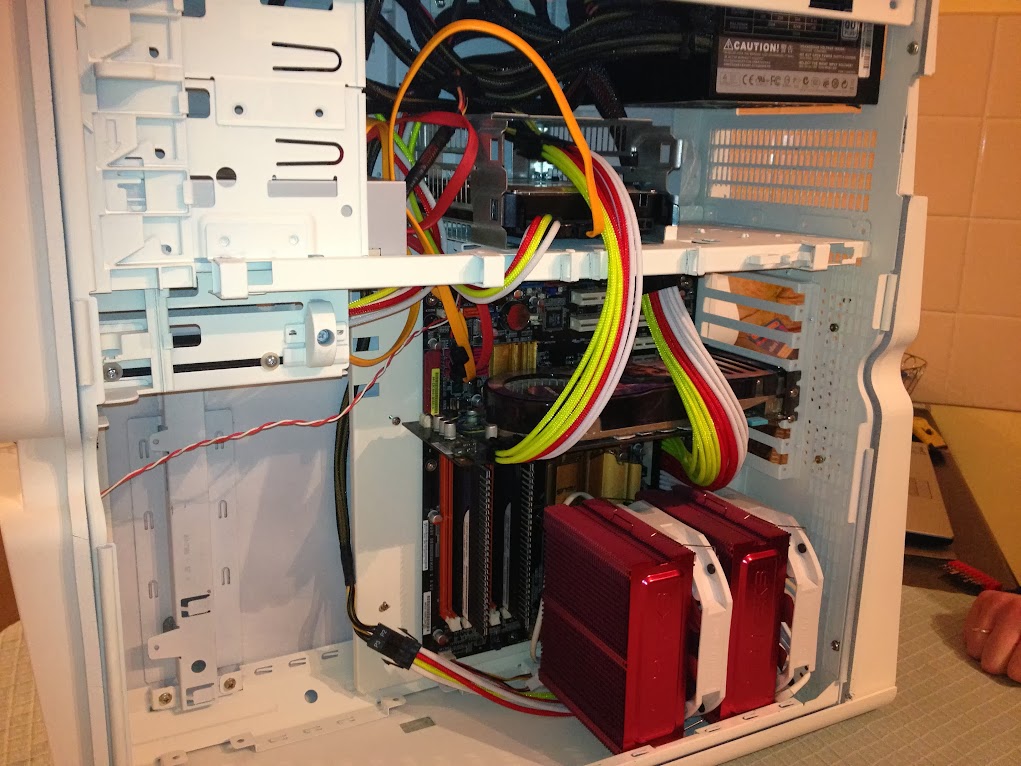
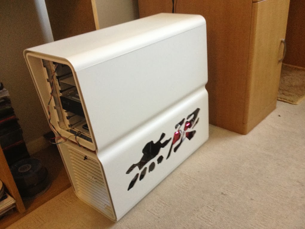
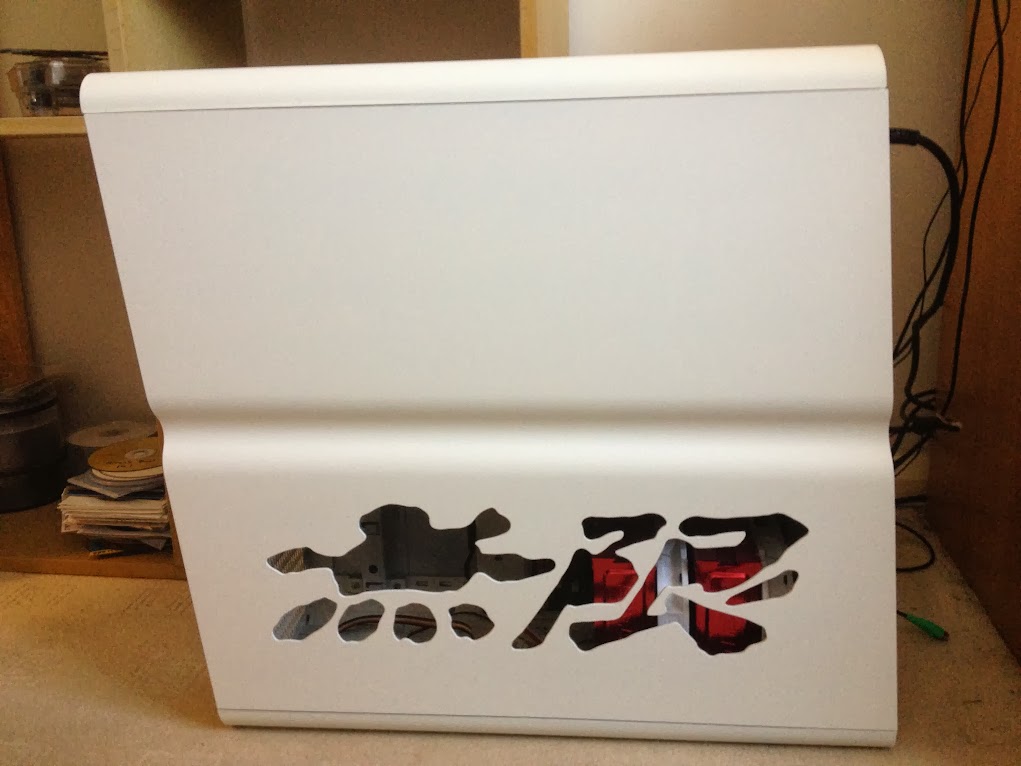
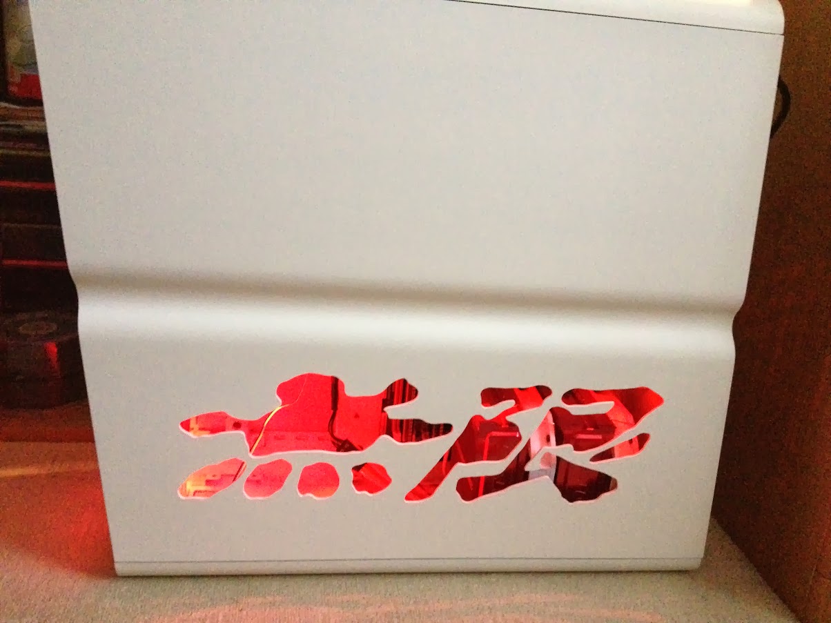
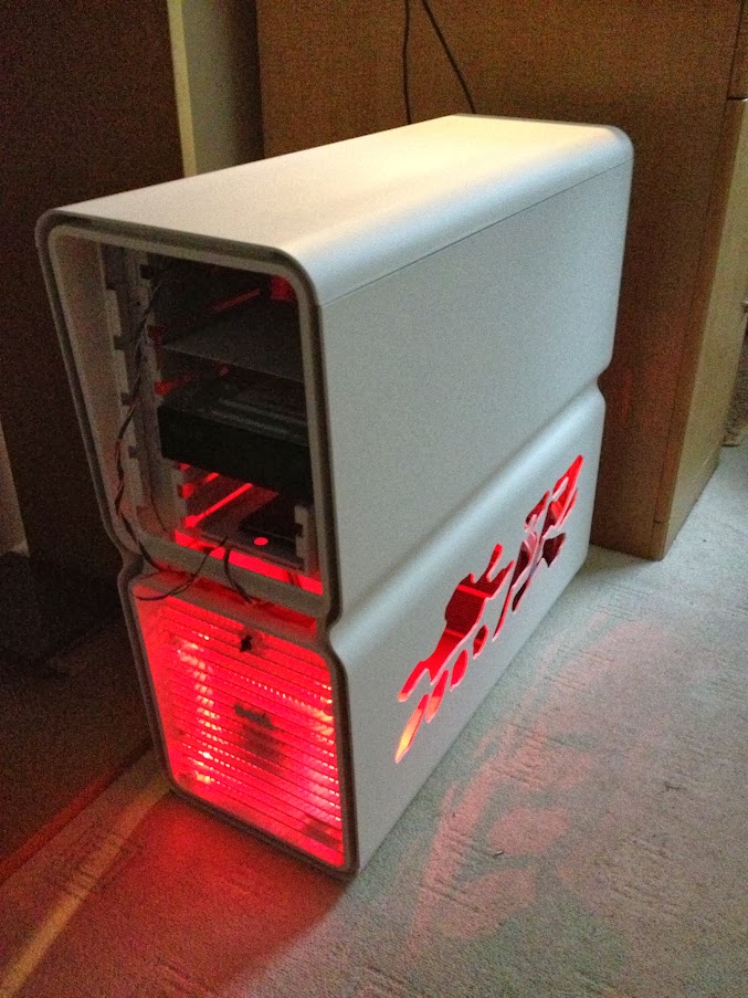
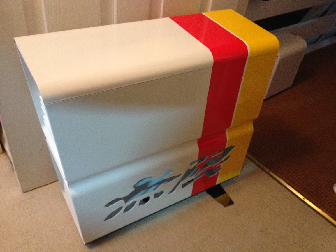
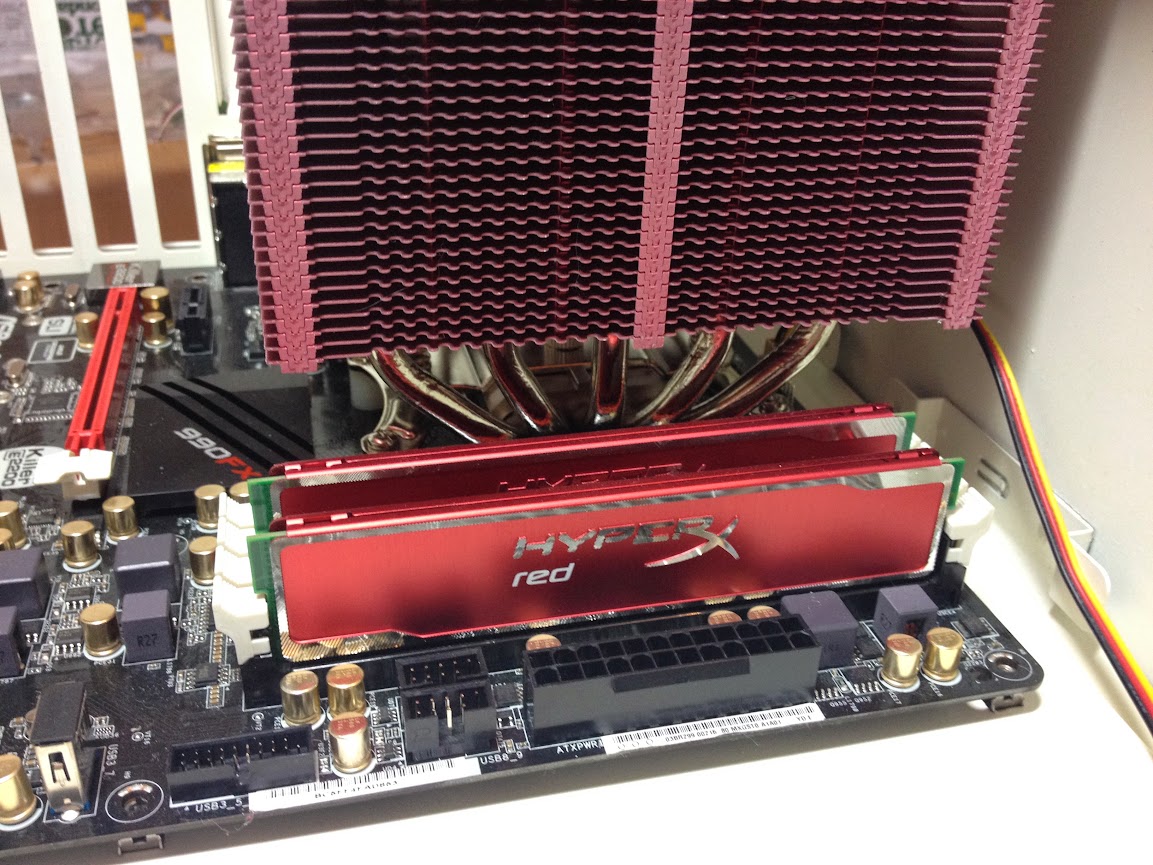
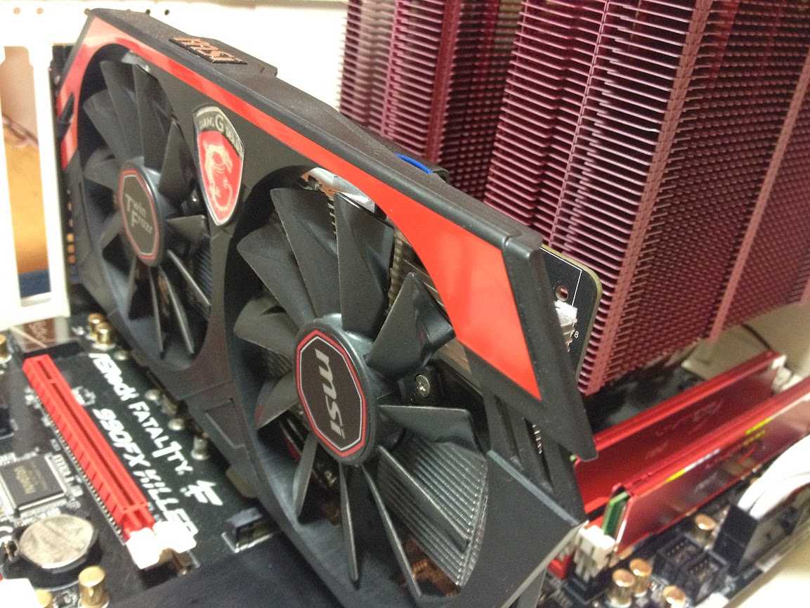
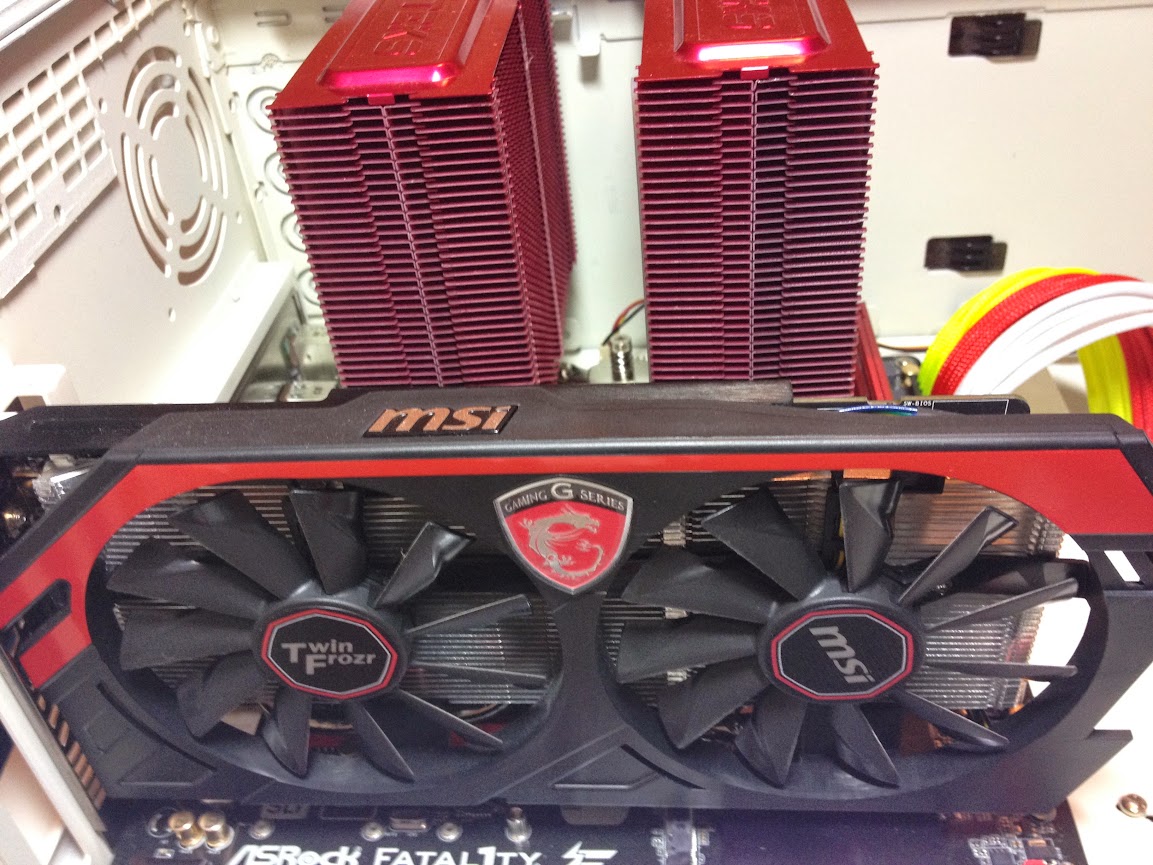
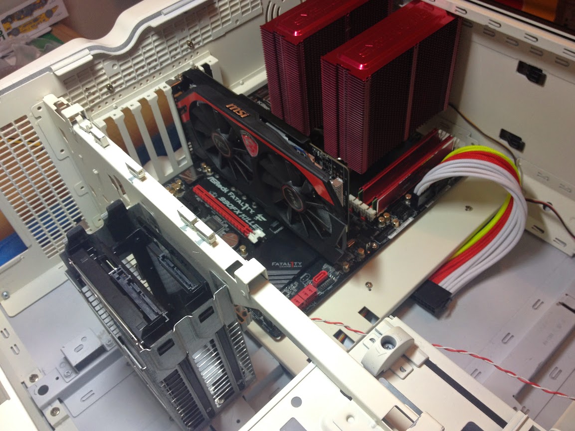
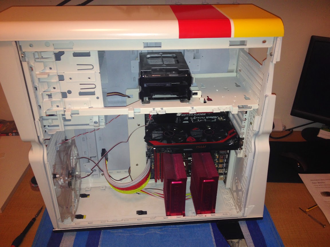
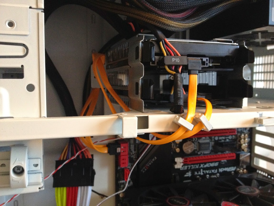
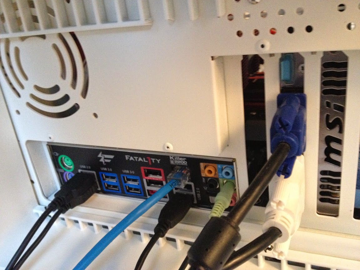
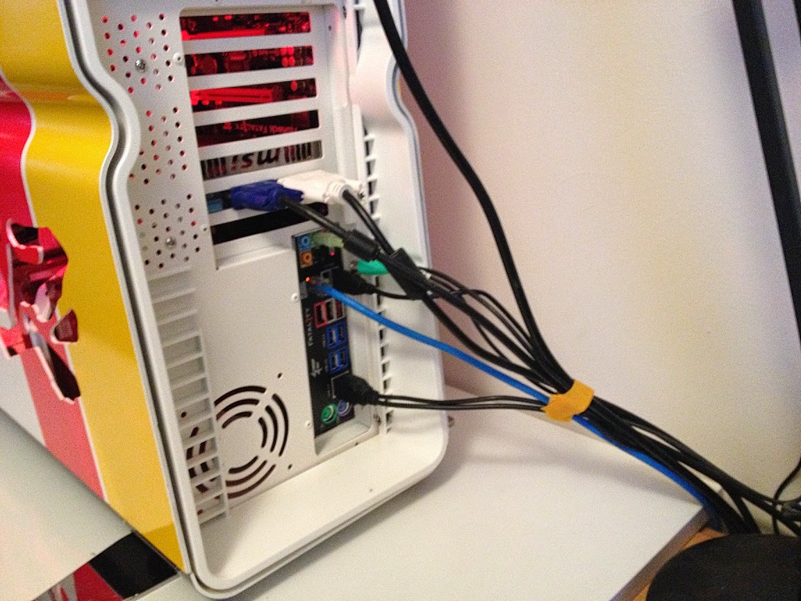
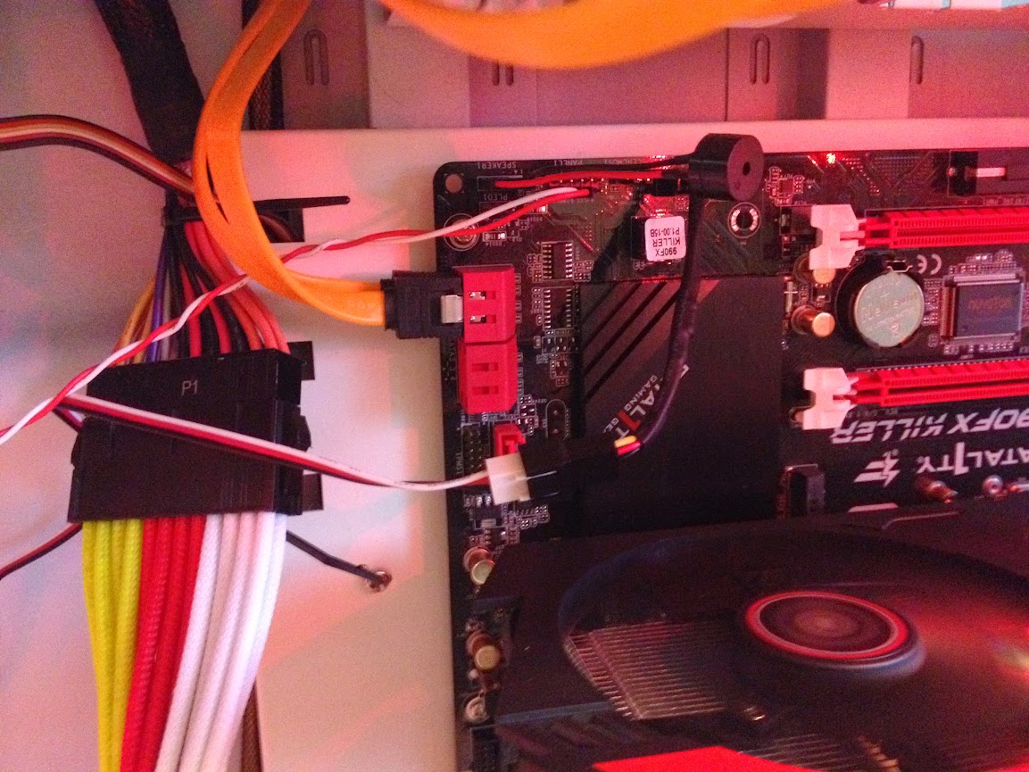
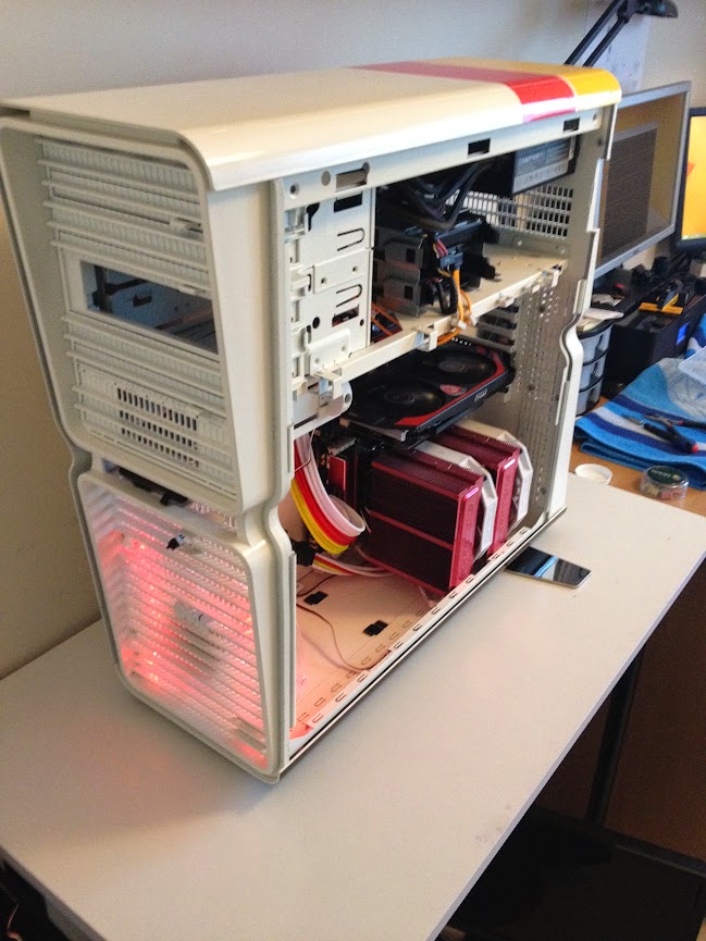
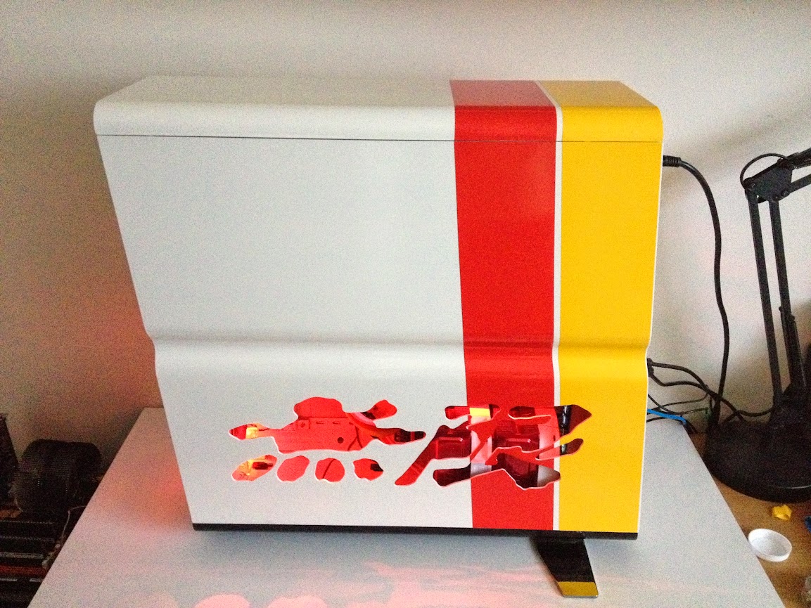
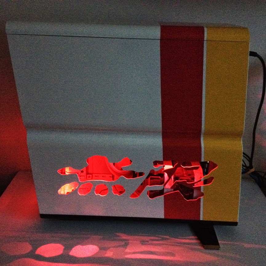
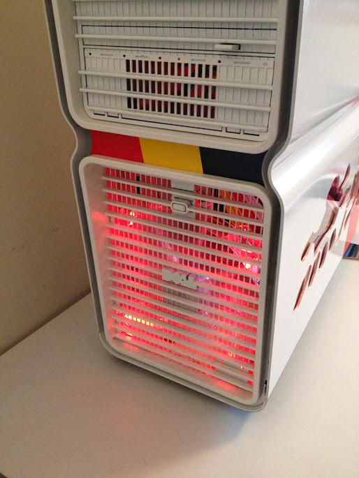
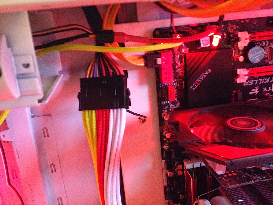
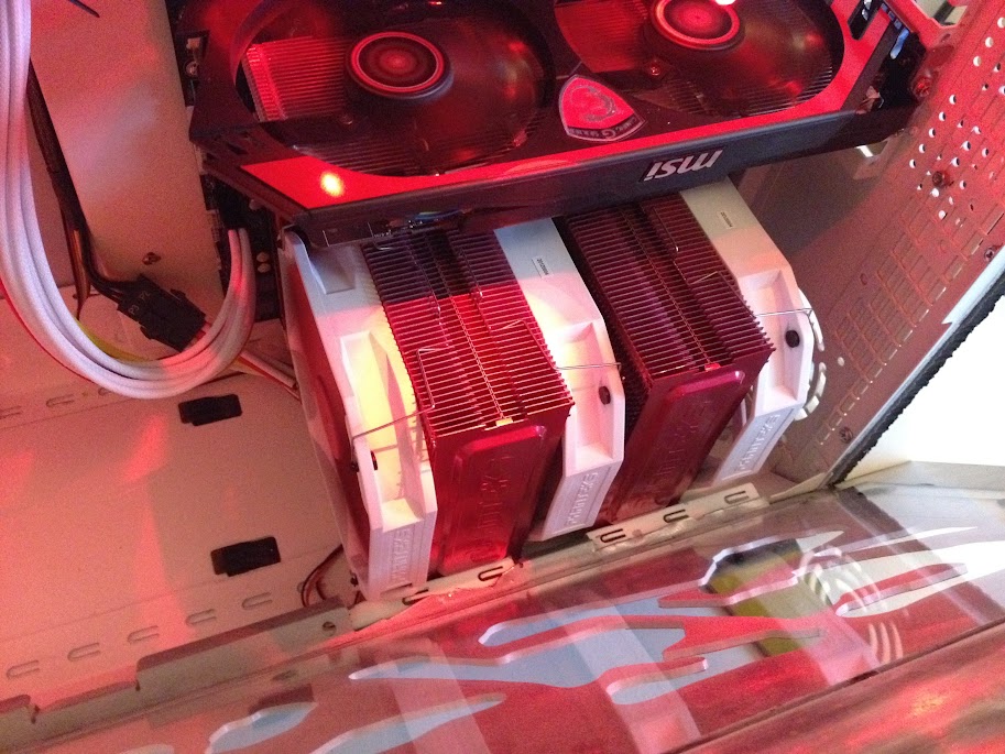
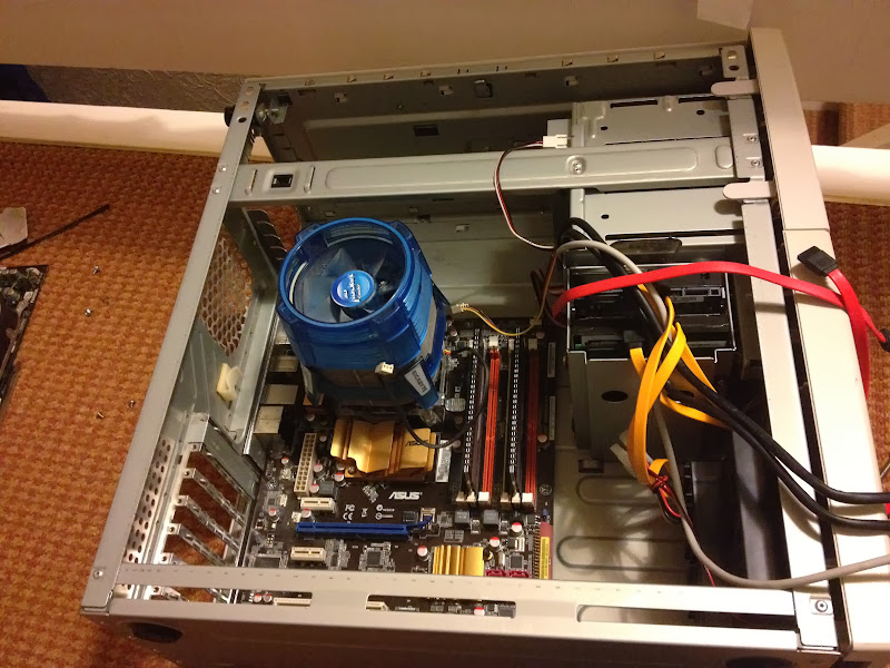
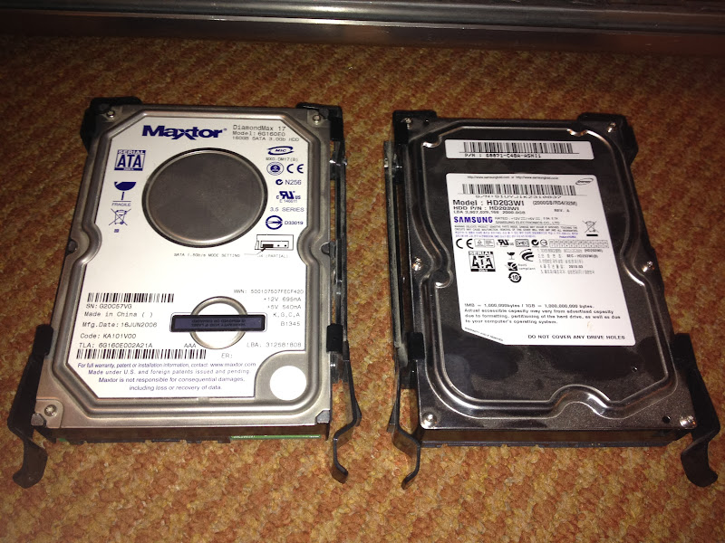
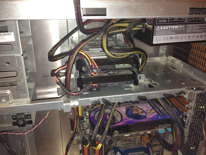
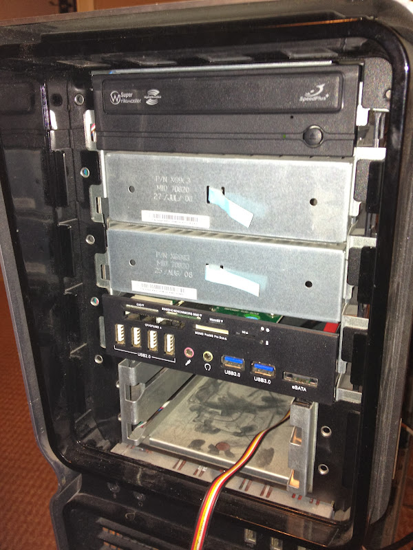
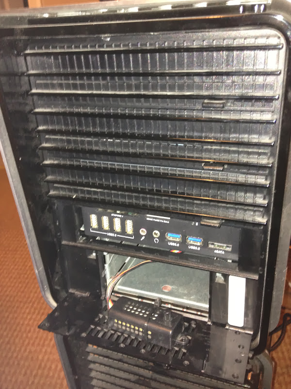
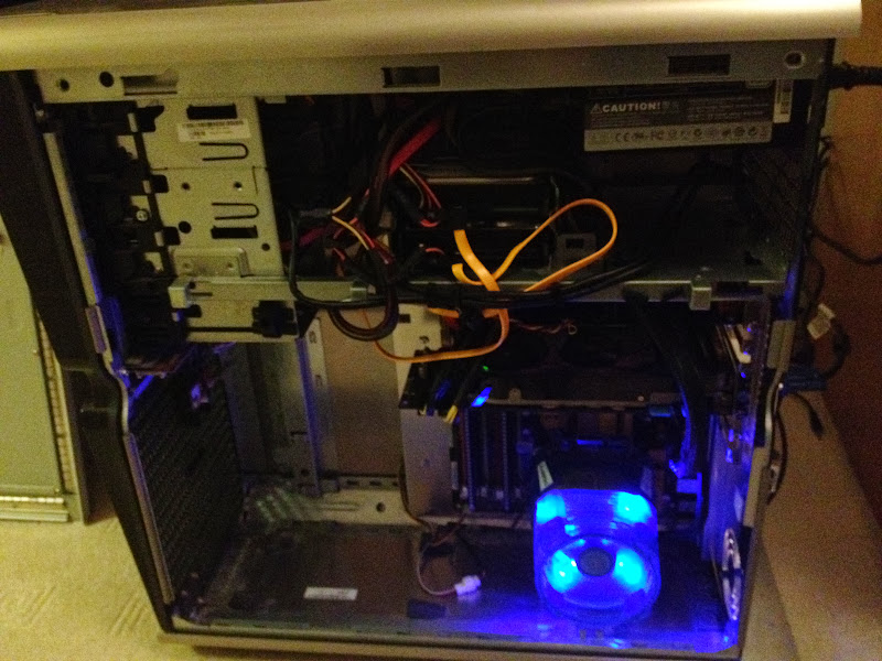
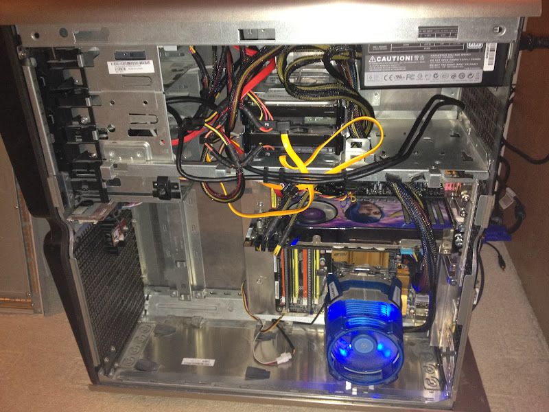
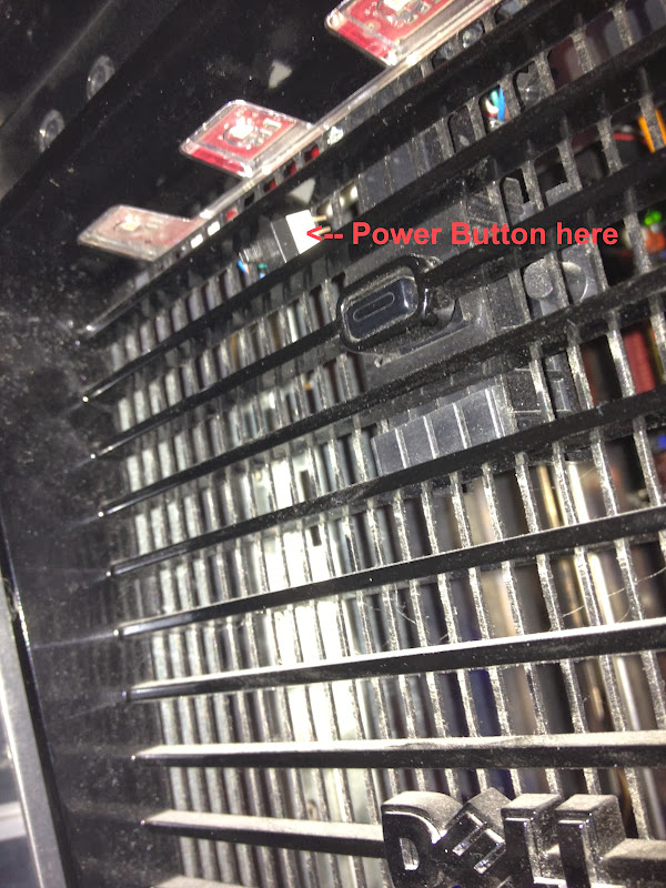
So... here are the pics from the moment the tray was in place, to completing the build to make sure everything fits right and works.

IMAGE_756429D8-582A-4EB2-A560-71FB62E91E17.JPG


IMAGE_9B92B7E2-CB31-4D8B-AEEA-15446B9E103D.JPG


IMAGE_3F3E34EF-4FC4-4F25-95F5-D9AE4799272C.JPG


IMAGE_FA915DCD-7E47-4C4E-9F80-5B060031DB7B.JPG


IMAGE_0821F7BC-D794-4C7B-87F4-17A1816D6C46.JPG


IMAGE_260755C0-C84A-41CA-9947-6AAEC64D67BE.JPG


IMAGE_AB2A8FAB-E8CE-45BF-9534-E354A129B6AA.JPG


IMAGE_099BF26A-D155-4595-8350-6F06452C5D0F.JPG


IMAGE_6B454A8F-2CDB-4AA3-81AD-D29265A3AEF5.JPG


IMAGE_82B98395-6CF0-456F-A566-356C138DF4EE.JPG


IMAGE_5C8F80D1-B0C3-4E77-9445-692EDA91342B.JPG


IMAGE_70DA2460-5F37-4196-A670-06328B28BDAA.JPG


IMAGE_CD9678CC-61AA-47E7-A8C5-F59B6A7659AC.JPG


IMAGE_36263A50-B410-48FB-ADE2-4DD7EF42A6E9.JPG


IMAGE_018D9BFD-B98D-4E71-8E33-EE433921F90D.JPG


IMAGE_6E08F705-95FE-4F52-B523-BF8974EAEAF8.JPG


IMAGE_CDCE5601-3B70-4038-BC4B-15969D4F2956.JPG


IMAGE_6A34F3A8-20CB-4FBB-B173-A8BB0CAE81D6.JPG


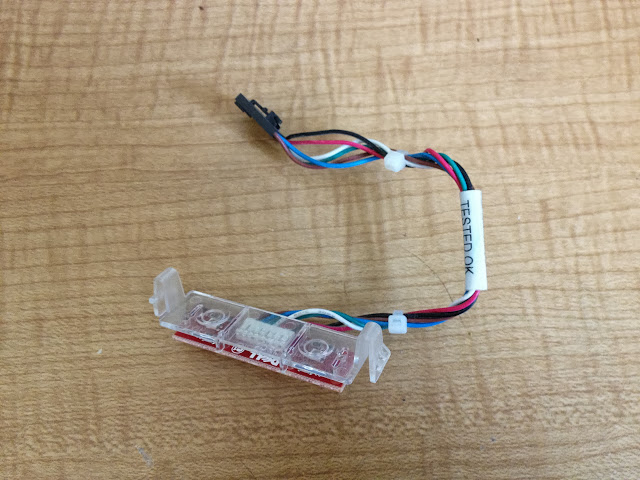
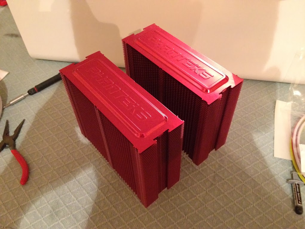
Now in the next coming week or two, I am planning to take it all apart again knowing it all fits in, and gave the case a proper clean, since it's been out of use for some time and doesn't look as good as it could be. And the cooling has to be updated. Can't bear the look (and sound) of the Gigabyte CPU cooler anymore.
 
Last edited:
Associate
OP
Joined
21 Jul 2009
Posts
28
Location
Swindon
Thanks guys. That was the only way to convert that case with reasonable time and effort. I saw someone's log doing it the way you won't be able to tell it's converted, but it took ca. 6 months.

Just need to sort out the cooling as it runs a bit hot without any case fans ;)
 
Last edited:
Associate
OP
Joined
21 Jul 2009
Posts
28
Location
Swindon
The power switch is a dell proprietary board and cable. I got some info on the connections used, but will need to find some more time to do this as I'm not that good with electronics.

And the cooler is driving me nuts. So what it was given good scores at performance, if it's so freaking loud!
 
Associate
OP
Joined
21 Jul 2009
Posts
28
Location
Swindon
Well here's the board, and the switch, with 6 cables ... lol

The board also controls the 2 sets of LEDs at the front, Audio jacks, USBs and IEEE 1394.

IMAGE_171B056B-CD96-4881-BE74-90B888401B01.JPG


Oh what joy ...
 
Associate
OP
Joined
21 Jul 2009
Posts
28
Location
Swindon
Done some digging and apparently I need this board from XPS 730.

In my XPS 720 the cables from the front panel go straight to Dell Motherboard. In 730 the went to intermediary board which was then wired to mobo. Also found a thread on some other forum with custom wiring and wiring diagrams.

There is hope
 
Associate
OP
Joined
21 Jul 2009
Posts
28
Location
Swindon
This thread is not dead yet. As a matter of fact is has become much more then just a conversion. The case will be modded heavily over the next few weeks. I have been ordering some custom parts etc, also speccing up some upgrades, and getting the LED switch designed and sorted.

Got a rotary switch and started to put the LEDs together, but I'd have good 20 wires running around to power and control this thing.

IMAGE_1617A075-82FE-4472-A1F7-F6BF8A076336.JPG


So ... I've decided to design a PCB board (my first) to manage all the LEDs and colour combinations. With some help, I got this:

IMAGE_FB0E01CD-6A87-4547-B72E-762B28ECF0C4.JPG


Also got an etching kit from Maplin. Will get the board done and tested this weekend. Then hopefully the part will start coming through :)

IMAGE_890B84DE-FDC9-4DDB-BD4A-F8484B05BD22.JPG


IMAGE_D6B41B1B-E1CE-49E3-9ABB-2F471C00F87B.JPG
 
Associate
OP
Joined
21 Jul 2009
Posts
28
Location
Swindon
My 3rd and so far best attempt on transferring the print onto the board ...

IMAGE_D3C64DEB-6897-450C-B53F-2D46B463D91C.JPG


Not sure if my iron doesn't get hot enough or the paper I've used isn't too good. :/
 
Associate
OP
Joined
21 Jul 2009
Posts
28
Location
Swindon
Used CD permanent marker to trace the missing bits.

Here's the board around 1h in the bath:
IMAGE_98CEFD90-6DC2-4661-80D6-CC4ADFF62A23.JPG


1.5h:
IMAGE_BD62BCFD-C0DD-4AD8-B8F5-160E9BBE634C.JPG


and cleaned result:
IMAGE_81249DB8-4183-406A-9AD9-E69009F9C42F.JPG


Few imperfections from where I've used the marker pen, but tested with a multimeter and it works!

Drilling and mounting diodes next ...

In the meantime, cables as being prepared by shakmods:
braided_mugen_cables.png
 
Associate
OP
Joined
21 Jul 2009
Posts
28
Location
Swindon
Hey. Here's how my back LEDs look. Not sure why yours are all black. Maybe if you assume they are wired in the same order? I am 99% sure they are just the same as front panel.

IMAGE_ED57F1A0-130E-40F0-99A7-181B7F0D6232.JPG

IMAGE_DE50B3CB-0BE6-4409-A0B7-ED4D5E64F8B4.JPG


RED = +
White = RED LED
Blue = BLUE LED
Green = GREEN LED
Brown = Ground

The only difference I just noticed is the extra 6th black wire, but I remember from reading somewhere else that other than that they were the same.
 
Associate
OP
Joined
21 Jul 2009
Posts
28
Location
Swindon
Sorry guys. Took a long time indeed to make any progress. This long weekend though have helped a lot though! The case has been sitting painted in parts for some time. I've finally managed to put it back together. Was not easy due to the way the mobo tray went on. Anyway, progress pics.

The LED board is coming along. I have a plan to put this thing and all the wires into a HDD bay and use IDE cables to connect the LEDs. Delayed due to the bay being delivered as damaged. Getting a new one sent tomorrow.

IMAGE_C538A547-7D56-4B04-8783-10B1D560C297.JPG

IMAGE_D417DB27-B19A-4C29-8979-A110CAB4CD30.JPG


Now, assembling the case (with getting some help from my cousin - he did the painting :)

IMAGE_EF7EBDCD-61E6-4F0C-B491-CCC933B85FC9.JPG


IMAGE_B710EC9C-15B8-4AA9-83B6-BB272A8942D9.JPG


IMAGE_FBB1DFC6-241C-4842-8A03-900E192FE737.JPG


IMAGE_40772E3B-FFDC-4543-8333-965EE9B0ECFD.JPG


IMAGE_5E952579-22F2-4614-BD53-43BEE9A15410.JPG


IMAGE_7671B416-9257-47AF-B5F6-20A1D574E941.JPG


IMAGE_C3B92DD3-D304-4B2E-8586-A88705CDEB9A.JPG


IMAGE_BBE238A1-41C4-4A1D-A7F9-48504A390ADB.JPG


IMAGE_4C1D15E5-A27E-4D66-8342-673E81AD4413.JPG


IMAGE_9AC99EA4-7EDA-4037-88E1-F9A309920509.JPG


IMAGE_3C702A97-27DC-42D8-9728-025800A1B031.JPG


2013+19%253A19%253A48


Things still to do:
- Front LEDs (delayed due to hdd tray delivered as damaged, which was to hold the PCB and colour dial)
- Red LED inside
- Front door panel to be painted
- Yellow and red stripes on the sides (possibly vinyl on top of lacquer finish)
- 200mm red LED fan to go to the front of the case

I will probably have a little break now of at least a week as I have some guests next weekend, but after that will be getting the case finished. Will work on the LED tray in the meantime.
 
Associate
OP
Joined
21 Jul 2009
Posts
28
Location
Swindon
Not much I can do about the cabling although I will have another look at routing them when I rebuild it again hopefully this weekend.

The front has something coming to cover the dell logo, and mugen badges are coming on the sides :) Look at the concept here
 
Associate
OP
Joined
21 Jul 2009
Posts
28
Location
Swindon
Sorry for not updating this for such a long time. Due to various things and events I was only able to return to the project in the recent week. The progress in this case have been very swift, and the build is now almost complete with some tweaks coming over this weekend, and few more updates in the next week or two, depending on receiving ordered parts.

So, here it is.

We've had some nice weather last weekend, so the case has received its lacquer treatment:

IMAGE_270.jpg

IMAGE_288.jpg

IMAGE_291.jpg


The red and yellow vinyl strips went on the side, with the black strip being put on the bottom part, to make it look like a side skirts on a car :) I was originally going to put all 3 colours on the side, but it was looking like a Belgium flag and wanted to avoid confusion :)

IMAGE_296.jpg

IMAGE_297.jpg


Some new components then went in. Upgraded my old Core 2 Duo to AMD FX-8350 on ASRock Fatal1ty 990FX Killer motherboard, and some matching red Kingston Hyper-X sticks.

IMAGE_298.jpg

IMAGE_301.jpg


Also used MSi GTX 750Ti Gaming OC Twin Frozr IV 2GB card. It does not require additional power, which works for me as it's less cabling and it's really quiet!

IMAGE_302.jpg

IMAGE_303.jpg

IMAGE_304.jpg


PSU, HDDs, Cooler fans going in (PSU is also being upgraded to BeQuiet Dark Power. Just waiting for delivery).

IMAGE_305.jpg

IMAGE_308.jpg

IMAGE_309.jpg


Back panel and cabling (matching yellow band)

IMAGE_311.jpg

IMAGE_316.jpg


That mess is being sorted this weekend with some additonal braided cables, sleeving and white perspex.

IMAGE_314.jpg


Powered on in daylight:

IMAGE_313.jpg

IMAGE_315.jpg


And in the dark (need to get a proper camera for better quality of the night time shots):

IMAGE_321.jpg

IMAGE_323.jpg


Will post another update after the weekend. Very happy with where I am with the build at the moment, and despite the delay I am still excited about this. Loving how it came out in the end! :)
 
Associate
OP
Joined
21 Jul 2009
Posts
28
Location
Swindon
More things done today. Just DVD bezel, PCI brackets, new PSU (went for Super Flower just ordered from OVerclockers ;) ) and Mugen badges.

IMAGE_332.jpg


Had to cut the power button bracket to fit over the 20cm fan I have fitted, but it worked out ok. Also braided the power button and fan cables.
IMAGE_334.jpg

IMAGE_336.jpg


3rd CPU fan and plexi-glass installed.
IMAGE_335.jpg

IMAGE_333.jpg


It's nearly done!
 
Back
Top Bottom