First Attempt at Waterblocks

Associate
Joined
21 Aug 2006
Posts
1,908
Location
Stafford
Just a quick hi as I have not been on here for some time. Been playing round with a NorthQ Siberian Tiger and been quite impressed.

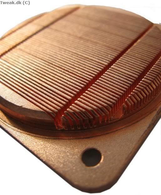
This has led me into the diabolical world of watercooling and being a must do it myself I have started construction of my X-factor water block.

It might not be as pretty as a commercial unit, but at least it is a one off. :p

75078519.jpg

16365466.jpg

41623258.jpg

13968568.jpg

44702761.jpg

18852393.jpg

39265645.jpg

64153423.jpg


Still a long way to go, but it is getting there. Any ideas or thoughts you guys may have may give me some inspiration.

Also can you see any potential problems I may have as I am still 'collecting' all the goodies for my water cooling setup.
 
Yup Enzotech Ram Sinks. The only metals present are solder, copper and the nickel plating on the barbs. Any problems with the combo ?

Oh yes and stainless steel bolts
 
Last edited:
do CPU blocks not follow a flow path like in GPU blocks? Just thinking that you might end up with a swirl of water just slooshing about if the block doesnt provide a specific route for the water to take?
 
I'm very impressed, nicely done :)

I agree with DampCat, the flow path is ill defined but this doesn't mean it's broken. In addition, you may get the best results when the inlet is directly over the pins of one of the sinks, preferably the centre sink but that would require a rebuild.

Anyway, you never know until you try it, any test results yet ? :D
 
No results yet. Still got to get a rad and some piping. I only have the NorthQ to compare against, but I am sure I can reference systems here on OCUK.

The theory is that the inlet floods the waterblock, forcing water over the centrre heatsinks, through to the outlet. Surplus water will find an alternative route once the main path is saturated.

78267594.jpg


I suppose a test run is the only way to find out. Below is test subject number 2. Any thoughts on what could be done with this one

73664956.jpg
 
Interesting use of ramsinks, though I'm not sure how the extra interface is going to affect the thermal efficiency. With these hand made projects I always wonder to myself do you do it because you just like the experience and pride of making your own kit, or do you geinuinely think it will perform better than an off the shelf block, as there is no doubt about it it is easier to just buy one?
 
I suppose it is one of those must do things.

I agree with your extra interface comment, hence project 2. It is a forged pin fin heatsink which in theory overcomes the interface element.

76387625.jpg


95291653.jpg
 
Interesting. Crude design but certainly worth a shot. The interface might well be a problem as previously suggested. I prefer the full square of enzo heatsinks which will most likely work better. The trick of making the block is to make sure you get the base flat, any ridges will kill the temps. Once you have mastered that then concentrate on the internals. I would be concerned about your method of sealing the block too. Are you sure it's watertight?

The materials you have chosen are all fine (close together on the metalurgy tables) so shouldn't present any galvanic corrosion.
 
Reminds me that I'm meant to be doing something similar. I think the first design implies a milling machine, so a flat base shouldn't be a problem.

For sealing, can I suggest solder? Cut a small groove on each piece, place solder along the groove, clamp then turn a blowlamp on it/stick it in an oven

edit: where did you get the copper from? the best I've found so far is 1/4" by 2" bar
 
Do a search on the bay for 'copper flat bar'. There is fome 10mm x 50mm there. All the copper is soldered so will probably be watertight.
 
Awesome! Not necessarily great technical work but this stuff is rare nowadays and used to be commonplace so I think it's great to see someone going DIY.

One easier way to do this is to think about how the WhiteWater was made. Thnk three layers.

image here
 
With the square (rev2) version - are you mounting the barbs in opposite corners.
Top left, bottom right so the flow travels across the diagonal.

Should improve efficency as you don't have a free flowing channel around the edge for center supply and edge extract like some blocks do.

Also consider if the top of the pins will meet the roof of the block - there is scope here of alturnatives the mass produced block just can't do.
Totally different design I know but the XSPC edge is a great example of a block that cost to much to mass produce but had a simple high flow multi-channel design (and preformace to match the best) no special plated or holes to reduce the flow the other big boys do.

Wish I had half the metal work skill / time. Would love make a direct heat pipe/fin high flow water block where you have more that the socket area to work within... That and be able to cut a straight line in metal :D
 
Last edited:
Really cool project. :) I like the second block - not too sure on the first - the x desiign seems a bit less than optimal and the solder interface can't be good for heat transfer.

About to do some copper to copper soldering myself - what type of solder and torch were you using? Any suggestions/problems you had soldering?
 
Looks nice - reminds me of the danger den rbx a bit, but would be better with more, thinner channels. :)

Are you using a CNC mlling machine? If so I'd go for a deep parallel fin design if I were making it, with the fins as tall and as narrow as the drill bits will allow before breaking - something like a 1cm tall fin, .5mm-1mm wide fin design, and sandblasted after if you have access to a sandblaster to increase surface area and turbulence would have utterly brilliant cooling - better than the best available commercially. The XSPC edge has around 54-55 fins , each ~0.3mm wide and 3mm tall:

12f9eed4.jpg


If you had slightly wider, but much taller fins, covering the entirety of the IHS (with the inlet and outlet off to the sides) it would perform much better, with very low pressure loss and massive surface area for heat transfer. I don't know the numbers on the heat transfer from the base to the fins, and I expect there's a trade-off between fin width and height - the thinner the fins the more you have but the bigger the heat differential between the fin temperature at the base compared to the top, but I suspect commercial companies haven't released taller finned blocks due to cost of copper and machining rather than performance.
 
Theres a really good reason why the edge does not have deeper, thinner fins. You can't cut them on a milling machine. The best you can do with a 3mm diameter cutter is about 6 mm deep. That'll break often. A 1mm milling bit stands a fair chance of managing a 1mm deep groove, but even that is pushing it a bit. Even under cnc.

Now the above is different, that can be cut with a slot cutter. Big cutting disk, moved in from the side. This is much better than a milling bit for small channels, but you need to be able to have the ends open. If doing this on a mill, I recommend talking to the technicians there. Limitations of the milling machine are a large part of why I haven't settled on a design yet.

Finally copper is a bitch to work with. Lovely ductile cutter grabs and holds onto cutting bits, so feed speeds and spindle speeds need to be carefully chosen. CNC would help greatly for this, but I'll probably be cutting mine by hand in a few months

Keep going though man, the second idea in particular has a lot of potential :)
 
Theres a really good reason why the edge does not have deeper, thinner fins. You can't cut them on a milling machine. The best you can do with a 3mm diameter cutter is about 6 mm deep. That'll break often. A 1mm milling bit stands a fair chance of managing a 1mm deep groove, but even that is pushing it a bit. Even under cnc.

Aha, okay, thanks for that.

Now the above is different, that can be cut with a slot cutter. Big cutting disk, moved in from the side. This is much better than a milling bit for small channels, but you need to be able to have the ends open. If doing this on a mill, I recommend talking to the technicians there. Limitations of the milling machine are a large part of why I haven't settled on a design yet.

Aha! Many thanks again - is there a rough guide for width of slot compared to depth achievable with a slot cutter?

Finally copper is a bitch to work with. Lovely ductile cutter grabs and holds onto cutting bits, so feed speeds and spindle speeds need to be carefully chosen.

I know.... Drilling copper is a painful experience.:(

/eyes stack of clamped copper strips with some of the 48 7cm deep holes done. :(
 
Taking all views into account I have ordered me one of these.

A75.jpg


clipboard01suh.jpg


The nice thing about the heatsink is that the base and fins are one unit i.e. no soldered joints.

Measures 100mm x 74mm, so I should get two WB out of one sink if I decide to chop it in half.

Some specs below

# Material: Copper C1020
# Dimension: 100x74x11 mm
# Pitch: 1.5 mm
# Thickness of fin: 0.45 mm
# Number of fins: 49
# Height of fin: 9 mm
# Height of base: 3.5 mm
# Length of base: 100 mm

Any thoughts on this one ???:)
 
Nice to see someone really having a go at this, I have drawn up (pro_engineer) a few blocks but I can't really be bothered machining them now lol.

GL with it, hope it proves worthwhile so keep us posted plz.
 
Back
Top Bottom