Anyone good with a soldering iron?

OK I've been to ******s and grabbed the power socket, a soldering iron and some other bits and will tackle this tonight!

if you have an old graphics card or mobo or a broken vcr or something lying around do some 'tests' on that to get a 'feel' for the iron, and the technique.

Did you get some solder braiding to remove the solder and/or a solder sucker?
 
if you have an old graphics card or mobo or a broken vcr or something lying around do some 'tests' on that to get a 'feel' for the iron, and the technique.

Did you get some solder braiding to remove the solder and/or a solder sucker?

Will find something to test on first.

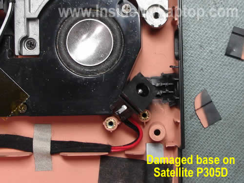
The pic iin my OP is confusing as it's even easier on my laptop.

Cut the wires off the old socket, strip the wire and resolder onto new connector! No need to desolder old socket etc as it's not on the mobo

repair-damaged-power-jack-21.jpg
 
A guy I used to go to school with once tried to stab a teacher with a soldering iron, I will bet that hes pretty good wielding one ;)
 
I've had this problem with my laptop for ages, I need to replace the connector and buy a new power brick as the connector on it is fubar too. The fact that the battery is also fairly dead and I'm close to buying a new laptop...
 
OK guys a quick question about the replacement socket.

This is the new replacement socket I got which has 3 lugs.
Do I take it that there are 2 negative terminals (outside) and 1 positive (in the middle)

Are there 2 neg's for ease or do I need to use both. Sorry complete newbie at anything like this!

Pic of replacement socket:

jk10l.jpg


Pic of the one in the guide and how it's connected:


guide1.jpg


guide2.jpg
 
Assuming it's center positive just wire up both external contacts to negative and the center to positive.

Get a multi meter out and verify the wiring.
 
You should also have bought a Digital multimeter for 5-10 £. Then you could verify for sure which terminal is which and whether you soldering skills have worked.
 
Put it to resistance and measure the resistance - 0 = connection, blank = no connection i.e. infinite resistance.

OK know which connector goes to the central pin which is the positive and if I put the probes on the other two connectors then I get a measurement which I guess means they are connected together?
 
I know nothing about the theory behind it either, but they do blow.

Stick a 19v, 6.32a psu in a 3.42a laptop and pop.

I thought it was the same as desktop psu's, as in, it'd have max ampage for the rail etc, but i've had quite a few die.

Erm, I think your getting confused. stick a 19v 6.32 Amps rated PSU in a laptop that requires 3.42 Amps PSU and it will run fine.

No pops nothing :)

Current drawn by laptop must be < than rated capacity of PSU, and by quite a long way for safety margins.


There seems to be a lot of people here who think soldering motherboards is a piece of cake, for the average person don't even try it. For one soldering a power connector can require a fair amount of power from your iron, because of the heat sinking of ground track...

Also, the +v rail pin on socket can be on a fairly fragile track, and if you get it wrong you'll just make a right mess of PCB

By all means go over joint if the connections have just gone dry (usually the case), don't go as far as trying to remove socket from PCB unless you have experience...
 
What goes where?
1. Take the new socket, not yet soldered in to the laptop.

2. Take the multimeter, set it to "V |: 20" (not "V ~ 20").

3. If required plug the black lead into "COMM" on the multimeter, and the red lead into "V/Ω/mA".

4. Press the red lead against the centre terminal on the new socket, and the black lead against one of the outer terminals.

5. If the reading on the multimeter is negative (probably about -18) then the centre pole is negative and needs to be soldered to the black wire inside the laptop.
If the reading is positive (about 18), then the centre pole is positive and needs to be soldered to the red wire inside the laptop.

Testing
1. Does the laptop turn on? (once it's soldered up, there is no less harsh way to test it then to plug it in and go for it).


You must be about 30 minutes drive from me, I will be going home to the Lakes this weekend if the car starts (battery on its way out). If you're not confident doing it I'd be happy to swing by and solder it up for you for a mug of coffee, it's a 5 minute job.
 
Last edited:
i would deffo ping out that new socket...

with 3 terminals one of them is probably a switched contact.. so when you plug something in it can disconnect something.

generally the terminal that exits the plastic body furthest away from hole for plug is for the tip (generally +v)

best way to test it, plug your PSU into it and get a meter on it (do this before soldering to laptop)
 
What goes where?
1. Take the new socket, not yet soldered in to the laptop.

2. Take the multimeter, set it to "V |: 20" (not "V ~ 20").

3. If required plug the black lead into "COMM" on the multimeter, and the red lead into "V/Ω/mA".

4. Press the red lead against the centre terminal on the new socket, and the black lead against one of the outer terminals.

5. If the reading on the multimeter is negative (probably about -18) then the centre pole is negative and needs to be soldered to the black wire inside the laptop.
If the reading is positive (about 18), then the centre pole is positive and needs to be soldered to the red wire inside the laptop.

Testing
1. Does the laptop turn on? (once it's soldered up, there is no less harsh way to test it then to plug it in and go for it).


You must be about 30 minutes drive from me, I will be going home to the Lakes this weekend if the car starts (battery on its way out). If you're not confident doing it I'd be happy to swing by and solder it up for you for a mug of coffee, it's a 5 minute job.

I'm a bit further down the road than you think (are you looking at my work location?) Anyway should I have the power connected to the new socket or not as I don't see how I'm going to get any volts otherwise?
 
OK done the test when powered up and I'm getting between 18 - 19v across 2 terminals. Other terminal doesn't register.

Do I take it that I've found the 2 correct terminals?
 
yeah plug your PSU from lappy into the socket and get meter on it...

before you do it verify your meter is correct by measuring the plug on end of PSU... shove the red probe down center, hold black on outer, it should read +v (not a - figure)
 
Back
Top Bottom