Best way to apply thermal compound!

Associate
Joined
15 Nov 2007
Posts
2,362
Location
Sheffield, UK
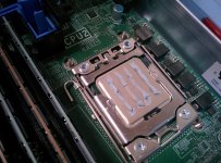
Just had a server board replaced under warranty on a Dell R420 who subcontract out to Getronics for "Engineering" work. Jesus wept at the job they did when they swapped the CPU's to the new board.
I was wondering why the fans were spinning up under almost no load, check CPU temps and they are off the charts.. **** me, if you want stuff doing right, better do it yourself.

lOjlheI.jpg
 
Shoddy, do Dell no longer come out on site to do the replacements?

Probably not - HP don't either in my experience (both Printer warranty and next day desktop warranty have been covered by 3rd parties).

In fairness to the "engineer" that did that - the Dell service manual (or at least the R410 one) says something vague like:
"apply thermal grease evenly to the center of the top of the new processor" - which he kind of did :D
 
Wow...

We did a HP Client refresh for all our users at the start of the year. We had 5 systems with bent mobo pins and one with no TIM. All replaced by HP but c’mon!
 
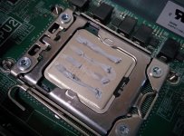
I honestly think it would have performed better with no thermal compound vs this :mad:. Not only is there not much where the die supposedly is near the center, but the thickness this was applied at was crazy. It's like they were doing a recreation of the Parthenon by putting the heatsink on pillars :o

But yeah all our Dell client, server, and Compellent work seems to be Getronics. This isn't the first time i've been unimpressed by the work :p
 
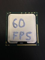
I always use the insulation tape method.

I put a 4 strips of tape all around the heatsink (one on each side) about a mm in, Then I spread the TIM out with a card using the insulation tape as a border. Remove the tape and then I have a nice square of TIM about as deep/thick as the tape.
 
I always use the insulation tape method.

I put a 4 strips of tape all around the heatsink (one on each side) about a mm in, Then I spread the TIM out with a card using the insulation tape as a border. Remove the tape and then I have a nice square of TIM about as deep/thick as the tape.

Thanks for the tip, sounds like a good idea. Do you think the tape leaves any residue on at all though?
 
Small blob approx. 6-8mm in diameter allows the pressure of the heatsink or pump head to spread it. when tightening the screws do up in a alternative corners pattern.
 
OP image doesn't even look real. Normal TIM spreads with pressure, yet all that shows is the original lines.

I use a small dob about 3-4mm in diameter. There is no reason to spread TIM over entire CPU IHS because all the heat is transferred from CPU dies that are only a faction of the size of IHS. The IHS is not really a heat spreader but a mounting surface to supply safe indexing and mounting of cooler. It's size is a direct result of size of PCB needed to support the 1000 or so connections between CPU and motherboard. The thickness of the IHS is too thin to spread heat more than a few mm from contact area of CPU die, so using more TIM only means the likelihood of it not spreading out enough to give us as much metal to metal contact as possible.

Be careful not to apply too much TIM. We want only enough TIM to fill the voids in the crystalline structure of the metal where it does not give direct metal to metal contact. We do not what TIM to form a layer between the IHS and cooler base
In case you do not know, TIM heat transfer is not even close to what good metal to metal contact is, but it is much better than what air transfers when there is no TIM in the voids created by the pores of the metal structure.

Heat tranfer ability of different things:
Copper is 400 W/(m·K) heat transfer
Aluminum 210 W/(m·K))
Lead is 35 W/(m·K)
Typical TIM is rated 3.5-10.5 W/(m-K) (GC Extreme 8.5W/(m·K), Chill Factor III 3.5W(m-K) in use this is only 1-2c difference in CPU temp)*
Air is 0.024 W/(m·K)​

To put that into perspective, any way you look at it metal to metal is 50 times better than TIM:
Copper is 47 times better than Gelid GC Extreme TIM & 114 times better than Chill Factor III
TIM is 333 times better than air at sea level.​


We need to keep in mind the area of IHS that transfers the heat from CPU chip is much smaller than the total top of IHS. It varies from CPU to CPU. While Intel chips it is generally a square or rectangular chip in the center part of IHS, AMD CPUs sometimes have the chips in the corners.

LL
 
Pea is what .. about 5-7mm diameter? That amount is about twice as much as I generally use and found to give best results. The exception being AMD CPUs with dies in corners. Only the area over die needs TIM. Applying more TIM means a layer of TIM between metal surfaces and not just TIM filling where there is not metal to metal .. both because of untrue surfaces of cooler base and CPU IHS and pores in metal surface leaving microscopic voids. Like I said above, metal to metal contact is 50 times better than having a layer of TIM between surfaces. ;)
 
Last edited:
Looks more like the heatsink wasn't fitted properly / faulty heatsink

Yes it does. For some reason the paste hasn't spread out at all.

It is more dangerous to put on WAY too little than WAY too much. Of course the aim is to get it right which is just enough to spread out over the top of the cpu. I tend to do the same as Doyll here which is a single blob about 4mm in dia. Warm the paste first and it should spread out really easily.
 
OP image doesn't even look real. Normal TIM spreads with pressure, yet all that shows is the original lines.

Heres a bigger/closer picture :p

f14QES2.jpg

As you can see from the picture above the TIM had a consistency of clay (Similar to IC Diamond). See the sharp/jagged break away and the way the TIM at the end supports itself from the removal of heatsink . If you ever have used paste like that you notice it immediately due to the great pressure required to get it out of the tube :p. Not all TIM is runny, especially at 18c. It's just disappointing that the "engineer" a) had this type of TIM on him, and b) pushed it out of the tube and thought it would work simply applied this way. Heat sink was fitted correctly, all 4 contacts are spring loaded and were securely screwed down.
 
If you look at a die shot of a Xeon 2400 or similar this isn't as crazy as it seems he just somehow didn't use thick enough lines or was using the wrong kind of paste for applying with this method.

It is best to read both the application guide lines of the paste and for CPUs of this size the recommendation for the processor.

In this case there is quite a lot of surface area to cover so you are best off using something that is designed for hand spreading or doing thick enough lines with a paste like AS5 which will spread enough under pressure of the heatsink.
 
Heres a bigger/closer picture :p


As you can see from the picture above the TIM had a consistency of clay (Similar to IC Diamond). See the sharp/jagged break away and the way the TIM at the end supports itself from the removal of heatsink . If you ever have used paste like that you notice it immediately due to the great pressure required to get it out of the tube :p. Not all TIM is runny, especially at 18c. It's just disappointing that the "engineer" a) had this type of TIM on him, and b) pushed it out of the tube and thought it would work simply applied this way. Heat sink was fitted correctly, all 4 contacts are spring loaded and were securely screwed down.
Yeah, TIM didn't spread at all. Not sure if it just the consistancy or a combination of not being mounted tight enough to force it to spread out. regardless it was a total FUBAR install. I have been building systems for 40+ years and that's the worst 'TIM print' (I use the word loosely) I've ever seen.

All this arguing about too little versus too much TIM is stupid. Anyone who has done any testing with amounts from as small as 2-3mm diameter dob up to 8-10mm dob or larger will tell you the same thing I said above. The 3mm dob seats and cooler as good as 6mm does and better then when larger amounts of TIM are used.
The key is to have TIM print pushing out TIM so cooler base and IHS are in direct contact with covering all of CPU die area under IHS. Any more TIM on increase the chance of a layer of TIM instead direct metal to metal contact with TIM filling voids.
LL


The below tutorial of TIM amount and application and resulting temps show what I'm saying. IIRC it was on a squarish CPU in center area of IHS

How to Apply Thermal-paste

Tiny dot is all that is needed. . A print like this on CPU is good. No surplus on heatsink. Temp is 50c

http://www.hardwaresecrets.com/article/What-is-the-Best-Way-to-Apply-Thermal-Grease-Part-1/1303/2


Small dot is biggest needed. Print is complete CPU & litte extra. Notice the surplus at top and bottom of heatsink . Temp is 50c too.

http://www.hardwaresecrets.com/article/What-is-the-Best-Way-to-Apply-Thermal-Grease-Part-1/1303/3


Bigger dot that is just too big. Surplus pushed out around CPU. Also on heatsink. And temp is 2c higher at 52c.

http://www.hardwaresecrets.com/article/What-is-the-Best-Way-to-Apply-Thermal-Grease-Part-1/1303/4


Keep in mind all of these are within 2c margin of error. In fact the temperature difference could be as little as 1c or as great as 5c.
 
Last edited:
Yeah, TIM didn't spread at all. Not sure if it just the consistancy or a combination of not being mounted tight enough to force it to spread out. regardless it was a total FUBAR install. I have been building systems for 40+ years and that's the worst 'TIM print' (I use the word loosely) I've ever seen.

All this arguing about too little versus too much TIM is stupid. Anyone who has done any testing with amounts from as small as 2-3mm diameter dob up to 8-10mm dob or larger will tell you the same thing I said above. The 3mm dob seats and cooler as good as 6mm does and better then when larger amounts of TIM are used.
The key is to have TIM print pushing out TIM so cooler base and IHS are in direct contact with covering all of CPU die area under IHS. Any more TIM on increase the chance of a layer of TIM instead direct metal to metal contact with TIM filling voids.
LL


The below tutorial of TIM amount and application and resulting temps show what I'm saying. IIRC it was on a squarish CPU in center area of IHS

How to Apply Thermal-paste

Tiny dot is all that is needed. . A print like this on CPU is good. No surplus on heatsink. Temp is 50c

http://www.hardwaresecrets.com/article/What-is-the-Best-Way-to-Apply-Thermal-Grease-Part-1/1303/2


Small dot is biggest needed. Print is complete CPU & litte extra. Notice the surplus at top and bottom of heatsink . Temp is 50c too.

http://www.hardwaresecrets.com/article/What-is-the-Best-Way-to-Apply-Thermal-Grease-Part-1/1303/3


Bigger dot that is just too big. Surplus pushed out around CPU. Also on heatsink. And temp is 2c higher at 52c.

http://www.hardwaresecrets.com/article/What-is-the-Best-Way-to-Apply-Thermal-Grease-Part-1/1303/4


Keep in mind all of these are within 2c margin of error. In fact the temperature difference could be as little as 1c or as great as 5c.

this is great info there are lots of ways shown on YouTube for example Linus tech tips 8s a great YouTube with info
 
Back
Top Bottom