DDR5 tuning - tRFC & turn around timings

Associate
Joined
24 Aug 2004
Posts
535
Location
Glasgow
Am still very much learning about DDR5 as this is my first AM5 board.

I came across this guide to tRFC caps on another board, but there was no reference to the source, does anyone recognise where it came from?

It was actually very helpful because on my dual rank(or is it quad rank with 2 banks per side on DDR5?) 2x 32G kit (Hynix M-die), I was seeing stress test errors with tRFC = 480 with TM5, but the same tRFC and even tighter timings (CL 28) passed an 8 hour Karhu run. tRFC = 496 passes both after a decent run

Went back to CL30, because despite an intake fan directly above the RAM CL28 needed 1.52v to pass some tests, and with max tREFI the sticks were getting a little bit toasty 58-61c. It's fine though with 64G+ expected to have to make compromises and very happy with 6200/2200.

I'm also wondering if it's worth trying to tune the turn around timings tRDRDSCL/tWRWRSCL. I've read up on what they do but I don't know if I should try and tweak them or what latency impact that might have, or what values they _should_ have outside of defaults when tuning DDR5.

Any suggestions here welcome.

mksoboZ.png
s46GUkG.png
 
this is because TM5 works

what ram kit do you have and what speed/timing did you actually get stable?
Ah sorry if that wasn't clear from the original post, the timings above are looking stable so far with shortish tests.

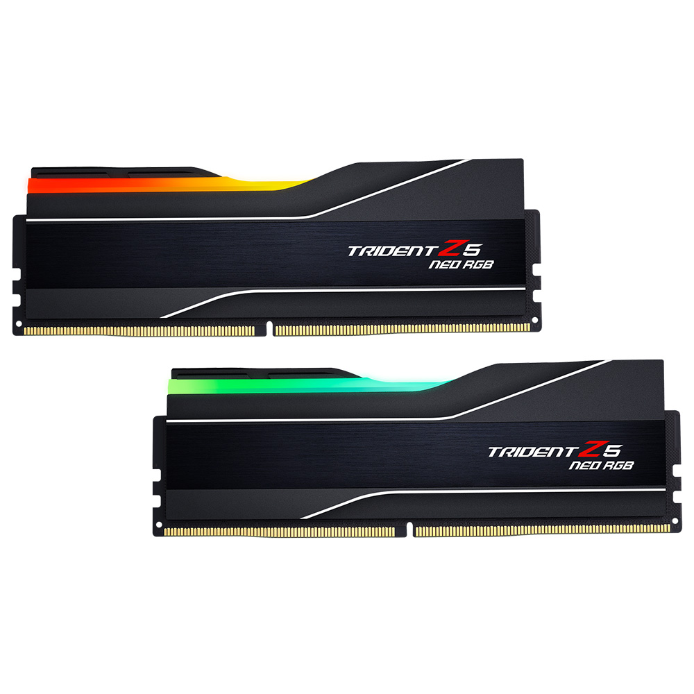
Kit is trident z5, F5-6000J3040G32GX2-TZ5NR


1hour TM5 (1usmus profile, previous instabilities would error after 10-25 mins or sooner), 4 hour y-cruncher all tests, 1 hour OCCT cpu+mem large dataset & AVX512

So what's interesting is CL28 (which needed 1.52v) passed an 8 hour karhu run (cache enabled), failed on TM5 within 15 mins.

Changes I've made since are vSOC from 1.48v to 1.46v, planning on a 1 hour TM5 tomorrow followed by a longer y-cruncher and I may well call it a day at that, have a CPU to OC still... ;)


4bUUmjn.png
 
Yep TM5 is very good at finding errors fast. If it fails it’s not stable.

Your dumping a lot of voltage in for not much real world gain. 32gb sticks are funny in some cases you would be better with 4 x 16gb, or 2 x 24gb sticks
 
The two sets of timings that are at 11, you need to tune them as you have dual rank sticks (they are ignored for single rank) 6-6 6-6 for both read and write should work but if not 6-6 8-8 should work.

RDRDSCL should go down to 5 or 6, WRWRSCL doesn't do anything afaik, it works at 1 and performance doesn't change.

There's nothing wrong with Karhu, one stress test is never going to give you the full picture of stability and you should continue to run multiple stress tests to verify stability (as you are doing).I just got done tuning my setup and I was failing Karhu within minutes on some configurations that were passing TM5 absolut for a few hours. Because you have 64GB though it takes a long time to get enough coverage to call it stable.

You're wasting a lot of time running the full suite of ycruncher tests, just hit it with VT3.

You should get your RAM temps under control (<55c) because it's going to be hard to determine if you're getting a heat related error (this can take hours) or if you have a timing set incorrectly.

Edit: BTW the source for trfc "calculator" is this hardwareluxx thead https://www.hardwareluxx.de/community/threads/ryzen-ddr5-ram-oc-thread.1324121/

It's quite an old guide though and most information there is somewhat outdated (it follows JEDEC spec strictly which isn't necessary) For example your TRFC or tREFI doesn't need to be multiples of anything, and you'll always get positive scaling (in terms of performance) with tighter values. trfc2 and tfrcsb isn't even used on the AM5 memory controller.
 
Last edited:
Reading various things I had come to this:-

tCl = Set as desire, can only be even.
tRCD = Set as desire, within AMD Overclocking menu separate tRCDWR and tRCDRD can be set, value is entered as hexadecimal.
tRP = Set as desire.
tRAS = tRC-tRP (JEDEC), tight tRCD+tRTP, only if tRC=tRCD+tRP+tRTP.
tRC = Higher tRCD+24+tRP+tRTP, middle >=tRCD+tRP+tRTP, lowest tRAS+tRP. See notes as tRCD+tRP+tRTP+2 maybe more optimal.
tWR = Lowest 48, multiple of 6.
tREFI = To be confirmed.
tRFC = Set as desire.
tRFC2 = To be confirmed.
tRFCsb = To be confirmed.
tRTP = Set as desire, lower than 12 unstable.
tRRDL = Lowest 8 (JEDEC).
tRRDS = Lowest 8 (JEDEC).
tFAW = Lowest 32, as rule is 4xtRRDS.
tWTRL = Lowest 16, as rule 4xtWTRS or 2xtRRDL.
tWTRS = Lowest 4, see notes as 4 maybe too tight.
tRDRDscl = Set as desire, match to tWRWRscl, lower than 4 unstable.
tRDRDsc = [Auto] is 1, lowering not possible.
tRDRDsd = Only relevant for dual rank, set as desire, match to tWRWRsd.
tRDRDdd = Only relevant for multi rank (4 DIMMs), set as desire, match to tWRWRdd.
tWRWRscl = Set as desire, match to tRDRDscl.
tWRWRsc = [Auto] is 1, lowering not possible.
tWRWRsd = Only relevant for dual rank, set as desire, match to tRDRDsd.
tWRWRdd = Only relevant for multi rank (4 DIMMs), set as desire, match to tRDRDdd.
tWRRD = Lowest 2, to be confirmed.
tRDWR = >=16, to be confirmed.

tCWL = No setting, "Auto" rule make it tCL-2.

Notes:-

DRAM VDD = DRAM VDDQ = VDDIO (ideal for data integrity)

tRFC lowering value best gains.

tREFI increasing value best gains.

tRC set to tRCD+tRP+tRTP seems too tight, as causes loss of mem speed in Kahru. Using tRCD+tRP+tRTP+2 seems optimal as gain mem speed in Kahru, which also means tRAS looser than tRCD+tRTP which is tight setting.

tWTRS set to 4 seems too tight, as causes loss of memspeed in Kahru. Using 6 or 8 seems optimal as gain mem speed in Kahru.

tRDWR on Auto is unsynced between memory channel 1 and 2 even at UEFI defaults.

If tPHYRDL unsynched between memory channel A and B, changing ARdPtrInitVal P0 Control can synchronise (9000 series CPU). Taking note of help string in UEFI, need to confirm is syncing tPHYRDL by adjusting ARdPtrInitVal correct way forward, as perhaps one channel is closer tracing to CPU thus 1 tick higher is not incorrect with higher MEMCLK.

FCLK VDCI Mode Pref to Predictive can improve stability with increased FCLK, VDCI = Voltage Dependent Clock Increment.

SOC is main voltage for memory controller (UMC), may help with FCLK increases.

VDDIO is a memory controller voltage (UMC).

VDDP is DDR PHY voltage.

VDD is memory chips voltage.

VDDQ is memory chips IO voltage.

VDDG CCD IOD, sync to one another, 900mV stock value, may help with FCLK increases.

For tRFC values reference this table, sourced from Reous's/HardwareLuxx members thread. On the left side of table are columns, representing RAM IC. In line to the top of a column is lowest value of tRFC a RAM IC will support. You might gain a bit more due to natural "silicon to silicon" variance, but won't beat it by wide margin.
 
Last edited:
Back
Top Bottom