Honda Mugen PC Case - Dell XPS 700 - BTX to ATX conversion
This is my first project log and case conversion ever, so probably won't be all perfect. The first mistake I know I've already made was not taking pictures from the start and before I actually started the conversion.
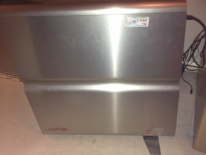
So the story is I got a XPS 700 case as a freebie, only to realise when I opened it up it's a BTX case. Having done some research and checked few other conversion threads, I decided to give it a go, since I really liked this case. And it was much better than one I had at that time.
Old case

Started off by getting a Lian-Li PC60 Motherboard Tray with back panel. Then took all the bits out of the XPS case in preparation. At this point the project got stuck for good few weeks, as it involved cutting out a large portion of the back of the case, to accommodate for the inverted expansion cards slots.
So when I finally got cutting it involved some drilling to get rid of the rivets holding the back panel, then cutting off the metal pieces that were in the way of the Lian-Li tray.
Before I fitted the Lian-Li tray, that had to be drilled and taken apart as well, as it just would not go in as one piece. Once in place, I used some screws and standoffs to join it back together.
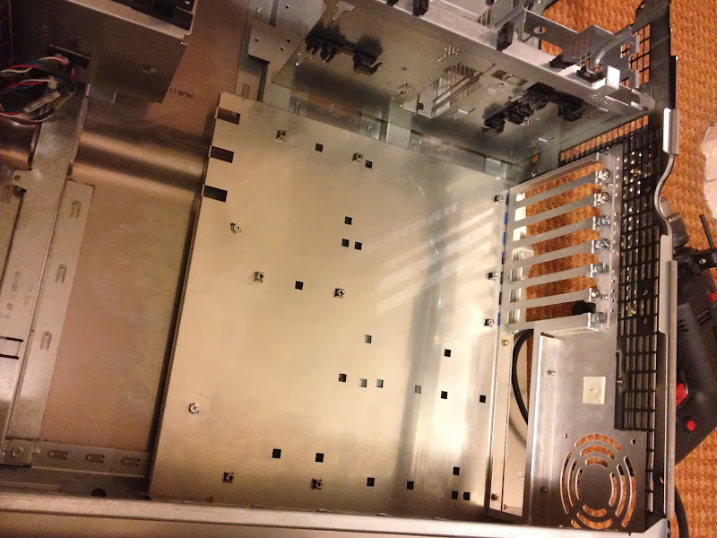
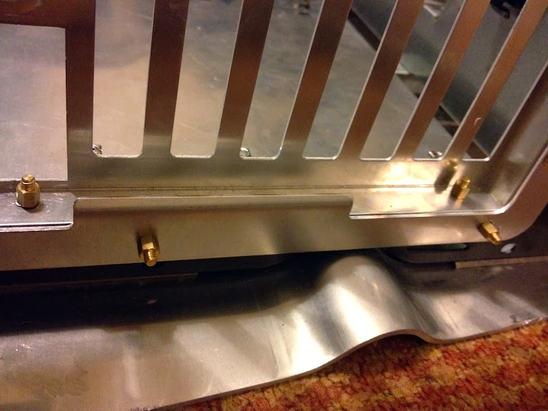
So... here are the pics from the moment the tray was in place, to completing the build to make sure everything fits right and works.


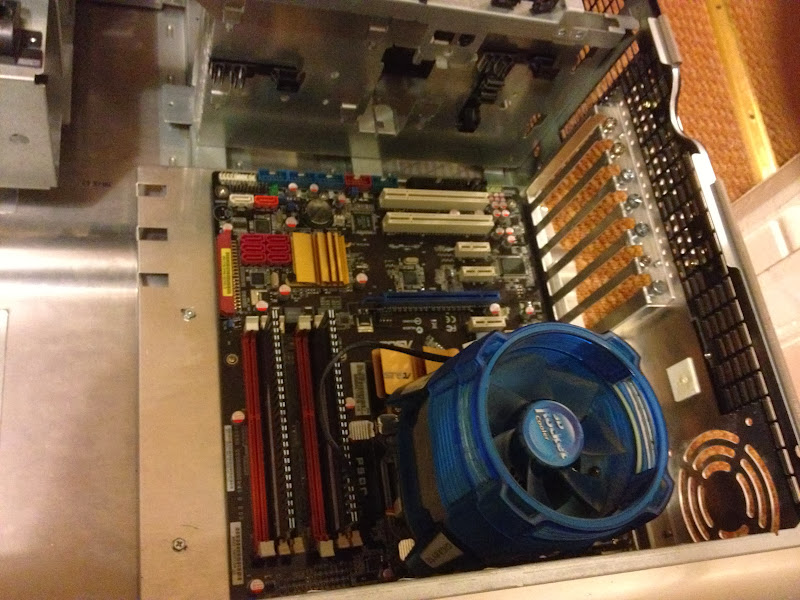

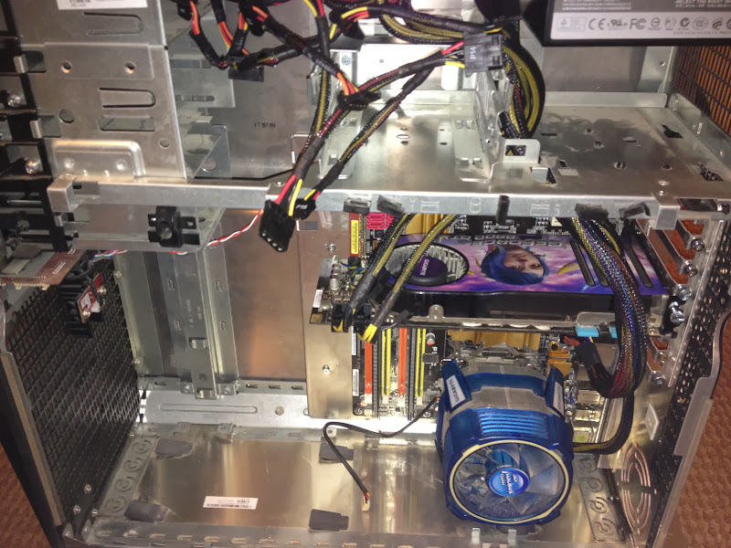
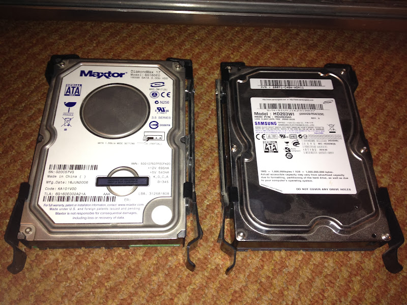
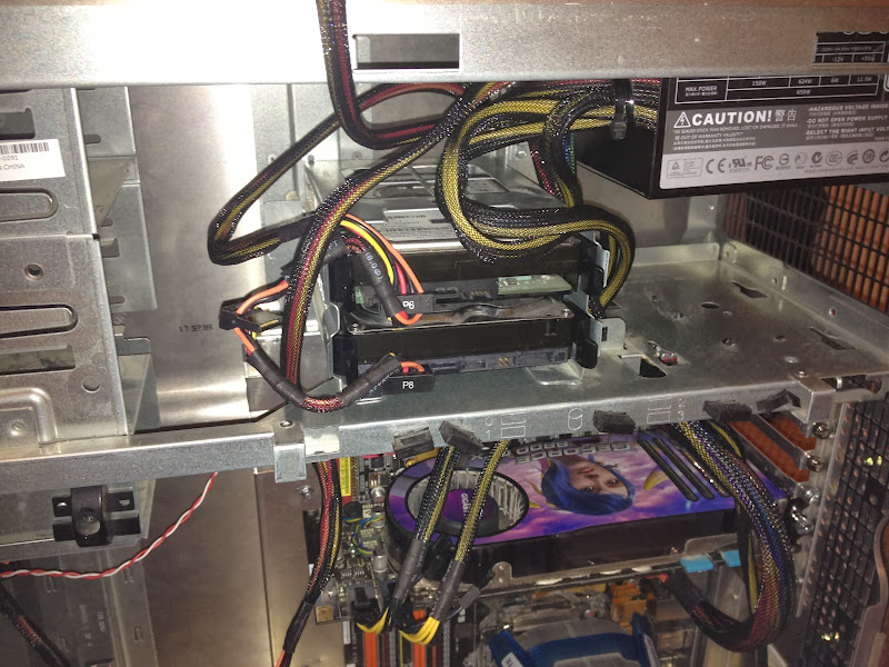
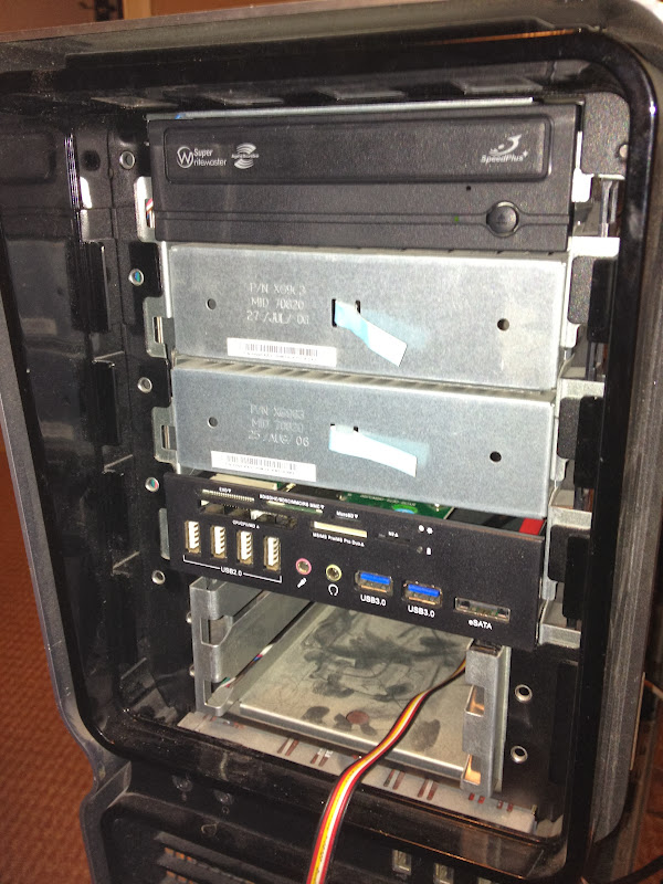

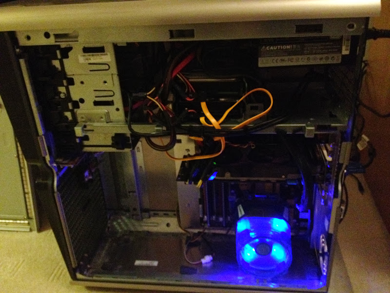
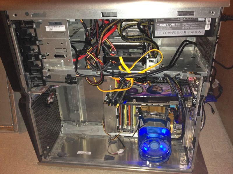

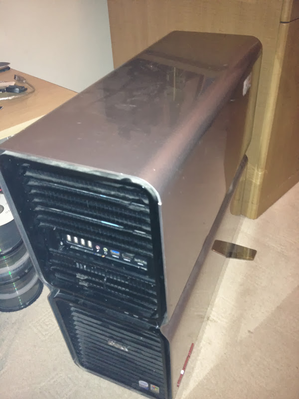

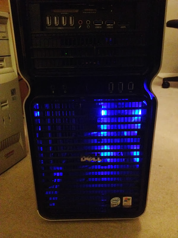
Now in the next coming week or two, I am planning to take it all apart again knowing it all fits in, and gave the case a proper clean, since it's been out of use for some time and doesn't look as good as it could be. And the cooling has to be updated. Can't bear the look (and sound) of the Gigabyte CPU cooler anymore.
This is my first project log and case conversion ever, so probably won't be all perfect. The first mistake I know I've already made was not taking pictures from the start and before I actually started the conversion.
So the story is I got a XPS 700 case as a freebie, only to realise when I opened it up it's a BTX case. Having done some research and checked few other conversion threads, I decided to give it a go, since I really liked this case. And it was much better than one I had at that time.
Old case
Started off by getting a Lian-Li PC60 Motherboard Tray with back panel. Then took all the bits out of the XPS case in preparation. At this point the project got stuck for good few weeks, as it involved cutting out a large portion of the back of the case, to accommodate for the inverted expansion cards slots.
So when I finally got cutting it involved some drilling to get rid of the rivets holding the back panel, then cutting off the metal pieces that were in the way of the Lian-Li tray.
Before I fitted the Lian-Li tray, that had to be drilled and taken apart as well, as it just would not go in as one piece. Once in place, I used some screws and standoffs to join it back together.
So... here are the pics from the moment the tray was in place, to completing the build to make sure everything fits right and works.
Now in the next coming week or two, I am planning to take it all apart again knowing it all fits in, and gave the case a proper clean, since it's been out of use for some time and doesn't look as good as it could be. And the cooling has to be updated. Can't bear the look (and sound) of the Gigabyte CPU cooler anymore.
Last edited:


 It's Gigabyte 3D Rocket II GH-PCU23-VE

