Diy chip amp project!

Soldato
Joined
13 May 2007
Posts
7,004
Location
On the wagon, sorta
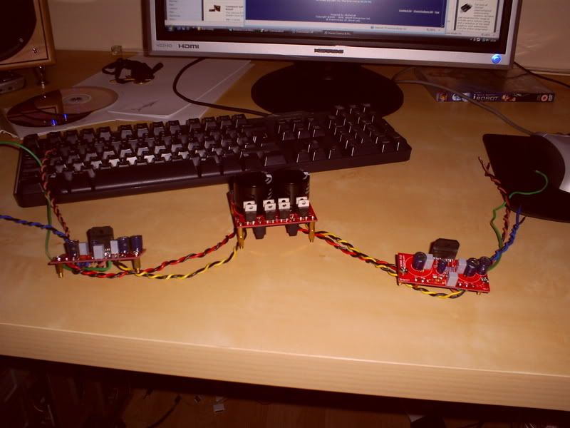
Some of you may remember me posting enquiring about D.I.Y chip amps, well i got around to starting a project and i thought i would share my progress with you all.

My kit came from WWW.CHIPAMP.COM and its based around the LM3886 chip, by all acounts its a pretty decent amp and great for a first project because of its low componant count and ease of build.
Sorry for the shots the old 5mp cam isnt getting old gracefully :(
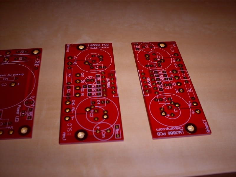
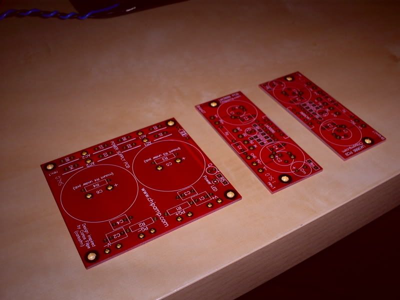
These are the pcb's as they arrive, I got a special deal and got a spare psu and amp boards for free with my order of the stereo kit.
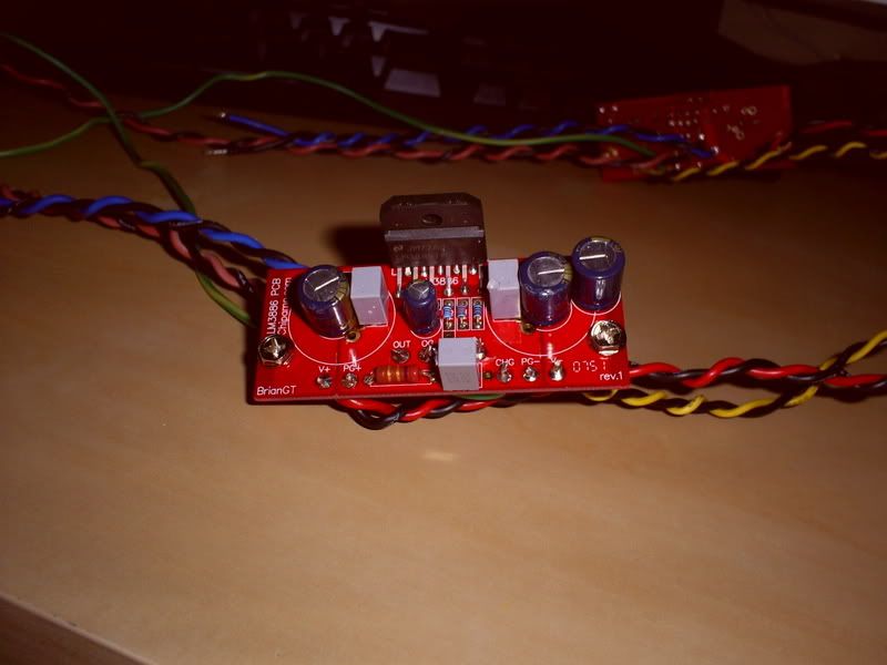
These are the amp bords.
S5030136.jpg

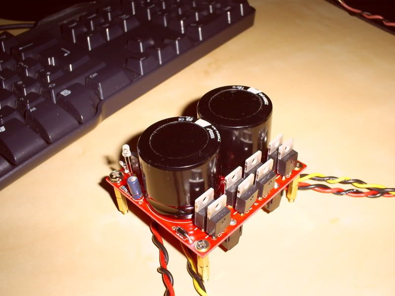
This is the pcb for the subberized power supply.
S5030135.jpg

Here are some shots of the power supply pcb's populated and solderd, looks nice and neat, i was suprised how well these turned out, all soldering is done with lead free silver/tin solder.
S5030134.jpg

S5030133.jpg

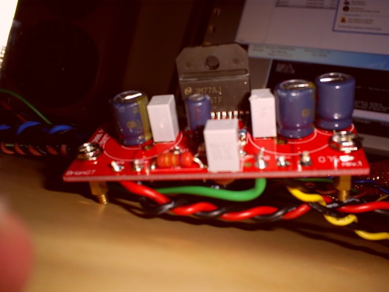
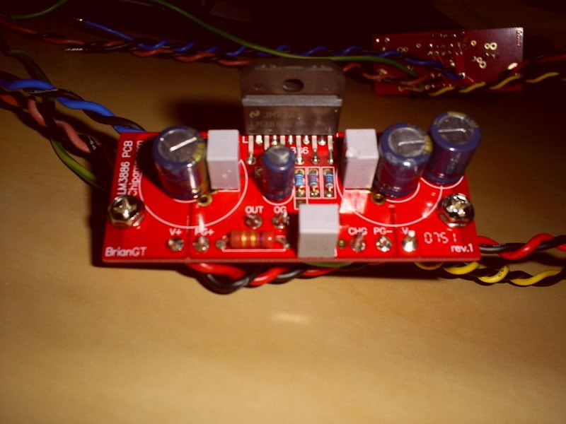
The amp boards were a lot of fun to do, the lm3886 chips i got came well packaged and were in top condition considering its journey form the US.
S5030372.jpg

S5030371.jpg

S5030373.jpg

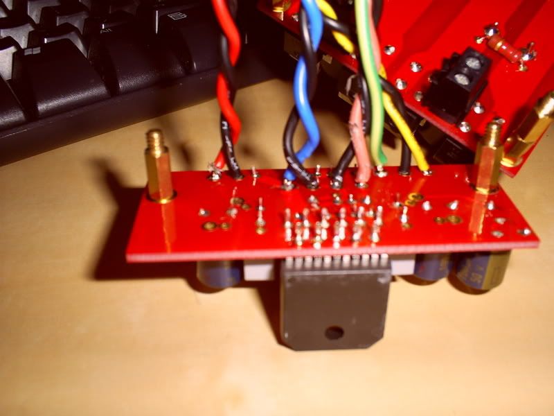
The underside to show the solder and input/output connections along with the V+ and V- points, and lastly the chasis earth.
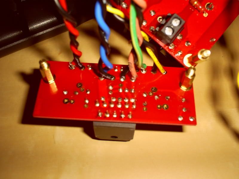
S5030374.jpg

S5030375.jpg
 
Im yet to buy a case for it as i wont be making one, im ordering one from germany i think, they are pretty decent all aluminium cases with an optional 10mm front face to give it that extra quality and look.
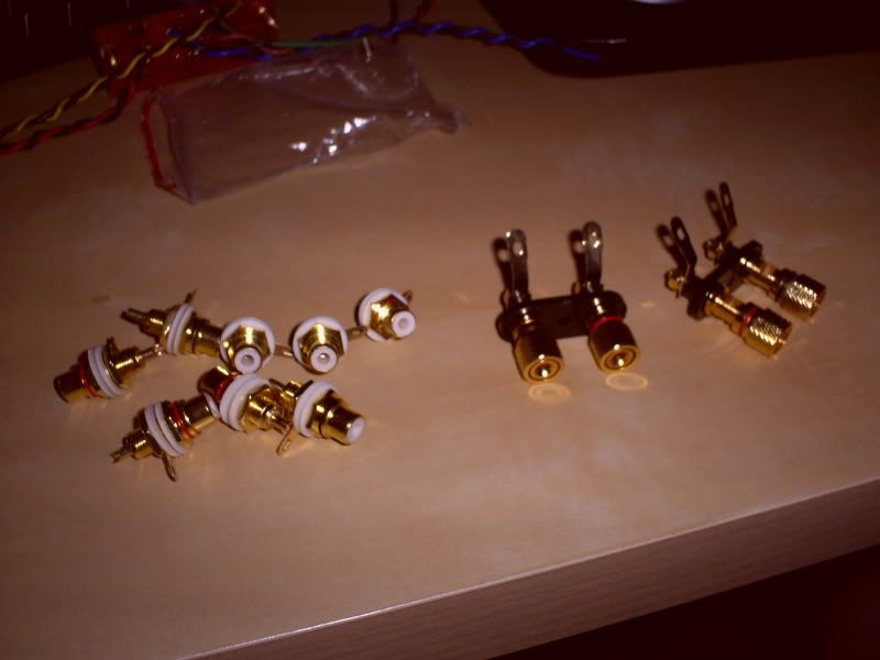
Ive got the connectors for the back
S5030137.jpg

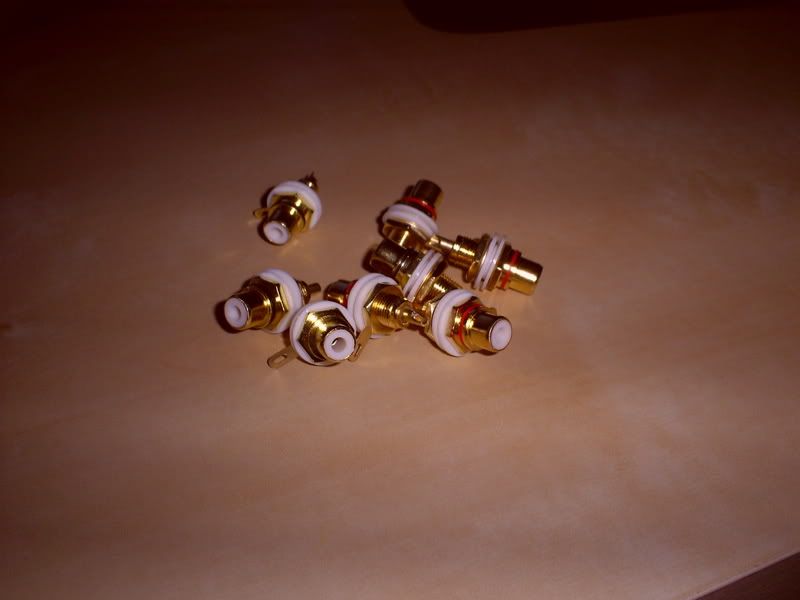
here are my RCA chasis mounts for my inputs, i plan to have 3 inputs.
S5030145.jpg

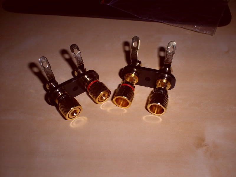
These are the banana plug binding posts for the speaker outputs, all the connectors are gold plated and look pretty sweet!
S5030146.jpg

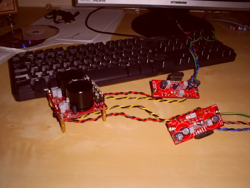
hear are some shots of the board together, all i need now is to source a toroidal transformer suitable for the project and i can get this thing fired up, im in 2 minds weather to have this as a power amplifier or weather to add a volume control and input selector in the same case, if i dont i will be making a pre amp to sit on top matching with the input selector and volume pot in.
S5030141.jpg

S5030129.jpg
 
cases and chassis try vt4c.com.

Also look at http://www.modushop.biz - very reasonable shipping to the uk.

for a pre amp i would use a stepped vishay attenuator or a well known auction site.

Alps pot would also suffice (again, maybe from vt4c).

Alternatively you could look for a valve preamp - they can really make chipamps sing.

Give me a shout if you want any other links, i have recently built a few amps :

Class D amp:

dscf0887nw5.jpg


dscf0886vy5.jpg


My DIY headphone amp and DIY usb DAC.

sohanx5.jpg


alienuo3.jpg
 
You will not be able to cut even basic holes with a dremel. The front panel is 10mm al, which with poor tools drags and clogs. If i were you i would get them to do all the prep and just pay the bill. I am lucky in that my fiance's dad has a good workshop with a bench drill, good quality drill bits etc.

For transformers - i use avel lindburg (US sourced). Alternatively just look at rapid or farnell, but you are normally cheaper form the us or asia. what sort of specs are you after?
 
doesnt sound far off for a chipamp. with that monster cap as long as you arent far under you will be fine. Question is what rails? +/- what volts.
 
I have no idea to be hounest, im gonna have to scour the diy forums to find other examples of the kit i think as im not having to much luck wiht the retailer at the mo.
Really excited about it though even to just get it on the test rig to run its burn in?/test run.
 
cases and chassis try vt4c.com.

Also look at http://www.modushop.biz - very reasonable shipping to the uk.

for a pre amp i would use a stepped vishay attenuator or a well known auction site.

Alps pot would also suffice (again, maybe from vt4c).

Alternatively you could look for a valve preamp - they can really make chipamps sing.

Give me a shout if you want any other links, i have recently built a few amps :

Class D amp:

http://img187.imageshack.us/img187/9488/dscf0887nw5.jpg[IMG]

[IMG]http://img388.imageshack.us/img388/5315/dscf0886vy5.jpg[IMG]


My DIY headphone amp and DIY usb DAC.

[IMG]http://img261.imageshack.us/img261/4858/sohanx5.jpg[IMG]

[IMG]http://img180.imageshack.us/img180/9113/alienuo3.jpg[IMG][/QUOTE]


That looks awesome. Could you possibly shre your circuit designs for those?

I've recently built headphone amp, and I've caught the DIY audio bug big-time!

[url]http://forums.overclockers.co.uk/showthread.php?t=17860076[/url]
 
Looking pretty cool, a little to advanced for me a from scratch kit but ill get there, id love to build the full tripath kit from 41hz but with the power supply boards amd boards and other kits you need to go in with it i think it totals out at around £180 just for the kits, then you need cases connector and other such gubbins.
By all accounts though a kick ass amp when done.
 
and very powerful with it, letting you drive even the most demanding speakers.

The 41hz kits are good, but similar to your issue with supplier - they tend not to pick up emails. I have to work my own problems out (cold joint on an inductor) when i am sure they have seen it a million times before. The fun and trauma of diy i suppose.

For the headphone amp:

currently its a basic SOHA amp but with an opa2107 in the output stage.

http://headwize.com/projects/cavalli2_prj.php

HOwever i have just ordered a E12 kit (delay and Dc offset circuit) to protect headphones from any turn on / turn off transients.

I will also add the all discrete buffers (jisbos) in place of the opamp and recase it in something nice.

If anyone wants a link to the kits : www.glassjaraudio.com
 
looking at the ps specs i reckon this would be fine for the tranformer

250 VA 18v,18v made by Avel Lindburgh Inc. (Y236651)

Just be careful with your ac wiring, follow the specs sheet carefully for 240v operation.

Also when mounting the kit, never try it without heatsinks, and make sure the chips are completely isolated from the heatsink.
 
Yeh forgot to mention i need to source some heatsinks, im thnking of using a couple of old pentium 4 sinks.
As for wiring the transformer, this will be my biggest hurdle, ive never heald a toroidal transformer never mind wire any type of transformer for any sort of opperation, i will be doing a little research into them before i do anything.

I sent the retailer an email the other day but have had no reply, these are pretty important questions i had for him so ill ask you lot just to clear it up.

Once the amp has been fitted to the test rig and powerd up, tested and confirmed working for a period of a few hours without a problem it will be needed to be moved into it's permanant chasis; what issues should i look for when moving it, ie: what componants will hold charge, and how do i discharge them to be 100% safe and, the transformer retain charge when disconnected from the mains and the psu board?
 
The P4 heatsinks should work ok, though they are designed strictly for fan cooling (close spacing of the fins, less effective for convection cooling). You appear to have isolated chips so mounting should just be a case of applying thermal paste and bolting it on.

The transformer won't hold any charge, only the caps will and it appears that they have resistors in parallel with them so they should discharge through these quickly. The amplifiers themselves will also take the charge within a few seconds; don't do what I did and disconnect them from the PS board first, leaving the power supply charged. It was the next morning I handled it without even considering it would have charge left and noticed my hands tensing when I touched it, 56V left in there :rolleyes::p.

Wiring the transformer isn't too difficult, but you must be absolutely sure it's done correctly! You'll need a double secondary type and that power supply board should make it really easy to connect. There are four wires and four connections. The transformers I have used are always coloured the same on the output wires and looking at it you'd have Red and Black to AC1 and AC1, and Orange and Yellow to AC2 and AC2. The primary (if it is a universal type and has 2 sets of windings) will need grey and violet connected together (and insulated!) and the brown is live and blue neutral.

Heres some reading regarding earthing for when you get to that:
http://sound.westhost.com/earthing.htm
 
Last edited:
Back
Top Bottom