DIY Headphone Amplifier

Man of Honour
Joined
13 Oct 2006
Posts
92,063
Some might remember I mentioned I was having a go at building one in another thread where I built a couple of basic ones - tonight finally got the result I was looking for :D

Quite a steep learning curve as I've not really touched electronics in any real way since dropping out of electrical engineering 15 odd years ago and I'd chosen the AD8066 op amp early on which being a high speed IC can't just be dropped into any old circuit with good results.

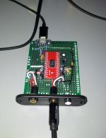
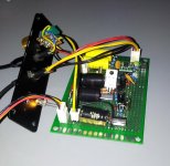
Not much to look at but image of the debug board - finally ready to commit the design to the final PCB (with some layout adjustment) and box it up (will upload pics of the enclosure when its all done):
0cAFgfc.jpg

(Some of the components at funny angles due to height restrictions on the enclosure I have in mind).

At its heart its basically a cmoy with some minor tweaking (mostly in regard to bypass capacitors) with goldpoint's experimental fully regulated virtual ground which seems to be the best power supply option with the 8066 - fully stable from 16 ohm through to 300 in my testing with plenty of power for the higher ohm headphones and no problems supplying the voltage for lower (no hint of clipping). AC/DC noise has been effectively eliminated when using wall power (its intended for desktop use) and there is virtually no background noise even with sensitive headphones - not even a hint of hiss until you really wind it up.

While ideally an op amp should be sonically transparent the 8066 does some magic with the bass that had to be heard - bass is really deep, extended and crisp and overall really happy with the sound - through the whole frequency range its pin sharp and punchy with good separation - playing something like Hotel California for testing the instruments have a satisfyingly lifelike quality. Only criticism is that the upper mid-range is a little bit what I believe is referred to as "veiled" and could be a little livelier.
 
Man of Honour
OP
Joined
13 Oct 2006
Posts
92,063
Very nice. Any chance of a circuit diagram or parts list?

I've just churned out my first CMOY, and whilst I've got parts for another 5 or so for mates, I'd quite like a different challenge. This looks ideal.

Largely its similar to cmoybb minus the bass boost: http://www.jdslabs.com/pdf/Assembly_cMoyBB.pdf though I'm using some different input capacitor values and 1-2 other resistors are different.

Couldn't seem to get desirable results from the bass boost with lower levels when combined with the 8066 and was a bit over the top when turned up so left it out.

The virtual ground is based off the 3rd image on this page:

http://www.head-fi.org/t/654485/virtual-ground-regulated-and-rail-splitter-circuits (the output diodes connect to the virtual ground).

I can't really recommend it as a virtual ground generally as it not a cheap option, takes up a lot of space, isn't efficient on battery power and has some questionable qualities from an engineering perspective (apparently) - your generally better off with the TLE splitter (from a lot of playing about unless you go with something really advanced the TLE seems the best option) but 1-2 high speed op amps like the 8066 seem to work best with it - sonically and stability wise in testing it I found it performs much better than the TLE or discrete based splitters with the 8066 - with the OPA2132, LM4562, etc. that I also have I couldn't really tell any difference.

Most of the changes from those designs are minor ones that I found worked best with the 8066 through experimenting.

(Not sure what version of the cmoy design your working off but with many op amps I found that the addition of rail bypass caps close to the IC - with some careful testing to avoid overly "hardening" of the sound made a huge difference to stability and using either an LD1085V or LM317LZ with an appropriate bypass capacitor as a filtering stage when using a DC power adapter cleaned up the background noise levels nicely).

EDIT: On the subject of challenges - the 8066 only comes as a SMD component (SOIC-8 1.27 mm pitch) so has to be soldered to a break out board (or used in a programmers adapter if you have space) if your using a regular DIP socket for the OP AMP which is quite fiddly though surprisingly I managed it fairly well... I picked up some PCM2902 USB DAC chips while I was at it which are SSOP-28 (0.635mm pitch) and is another story again :( if I can find a programmers adapter thats not like £90 for them I might just go with that as I don't seem to have much joy soldering them by hand hehe...
Nice work, you must be really chuffed that not only does it work as planned but it sounds so good.

I look forward to seeing it on the final PCB :)

It is quite satisfying to finally get the results I'd hoped for - while a cmoy is not exactly the most advanced design in the world to work with and well trodden ground its a fair step up from my experience level going in.
 
Last edited:
Man of Honour
OP
Joined
13 Oct 2006
Posts
92,063
Cool, no idea what any of that means but I guess I should take it in as I was looking at doing something similar before. How much did it/ will it cost overall? It's nice that that there's some cheap kits out there I recall looking at some t amps from China, the same ones used in the cheap class D amps?

You "can" build one really cheap <£20 but I don't recommend it - the first basic cmoy I built was with mostly cheap parts sourced from amazon, ebay, etc. mostly generic chinese capacitors, resistors, etc. even though the specs on paper were acceptable 1% tolerances, etc. (and they seemed to perform well enough for non-audio use) the noise floor of the resulting cmoy was atrocious - even at low volume levels there was significant background hiss and whistling type noise.

For reference incase anyone else is thinking of building one the original article by chu moy:

http://headwize.com/?page_id=707

Tangent does an excellent job of breaking it down for anyone with basic electronic skills:

http://tangentsoft.net/audio/cmoy/

However I recommend working off the JDS labs design once you have your head around it:

http://www.jdslabs.com/pdf/Assembly_cMoyBB.pdf

As 1-2 tiny changes they made make quite a difference to the end result with only a small level of extra complexity - though you might want to skip the bass boost part for a first build.

From my experience (and seems to be generally the advice) if you stick with an OPA2132 op amp you can build a decent high sound quality, stable op amp with only using a simple resistor divider for the virtual ground, if your wanting to use other op amps then either using a TLE virtual ground or as tealc mentioned another op amp as the ground seems to produce the best results - however its an extra level of complexity if your starting with minimal electronics knowledge.

I tried a few different versions of the virtual ground including various discrete component based ones like sijosae's rail splitter and while some of them performed really well from an engineering perspective I was never quite convinced they weren't detracting from the sound quality.

Also as I mentioned above if your going anywhere near a dc adaptor rather than battery power I'd strongly recommend a filtering stage based around an LD1085V or LM317LZ as it makes a big difference to background noise.

Price wise I didn't really approach it from a value for money perspective - after the first bit of playing around I did an order from Mouser for about £70 with enough bits (op amps aside) to build like 5 headphone amplifiers like randal heh.

Nice.

Looks similar to my design that I put together a few years ago, apart from the virtual ground circuit, for which I used a jelly bean op-amp to split the voltage. I also used a DIP package opamp rather than SOIC or MSOP.

The 8066 only comes in SOIC form and while its probably not intentionally the case I can kind of see why as you struggle to really do it justice on a bit of prototype board heh - 145MHz 180V/us slew rate compared to the more typical 10s of MHz/slew rate of more commonly used op amps.
 
Last edited:
Man of Honour
OP
Joined
13 Oct 2006
Posts
92,063
EDIT: On the subject of challenges - the 8066 only comes as a SMD component (SOIC-8 1.27 mm pitch) so has to be soldered to a break out board (or used in a programmers adapter if you have space) if your using a regular DIP socket for the OP AMP which is quite fiddly though surprisingly I managed it fairly well... I picked up some PCM2902 USB DAC chips while I was at it which are SSOP-28 (0.635mm pitch) and is another story again :( if I can find a programmers adapter thats not like £90 for them I might just go with that as I don't seem to have much joy soldering them by hand hehe...
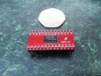
Going in a bit blase (soldering the PCM2902) with 60/40 and no flux didn't exactly end well... managed to clean it up and had another go with 63/37 and plenty of flux and think I've got it though not entirely sure if all the pins are soldered well enough, think I've managed to not get any bridges this time though.
 
Man of Honour
OP
Joined
13 Oct 2006
Posts
92,063
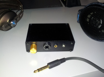
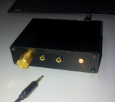
While still going to do a proper build and this is only representative of the final thing (better layout, more decoration/features, etc. - got some fancy surrounds for the LED and so on) ended up boxing up the prototype build as I was using it so much and I'd scratched the case up pretty badly anyhow in testing things out (fortunately had the foresight to order a few of the enclosure).

ik964TX.png

Really enjoying listening through it to be fair even with headphones that don't need amping - while it is a bit "veiled" the separation, detail and low range performance are perfectly to my taste.

(Quite hard to take a good picture of it with the lighting in here as well - it looks a bit better in the flesh than the phone camera can handle with the mixture of light and blacks)
 
Last edited:
Man of Honour
OP
Joined
13 Oct 2006
Posts
92,063
I'm going with inputs on the rear with the final version (I actually cut holes for it on this one but not used hence no picture of the rear as it looks a mess) - RCA would be a good idea though.

Most of my headphones (600s aside) use 3.5mm though I did really start the whole thing originally with the 600s in mind. I did experiment originally with 2x 3.5mm output (one setup for low Z) plus 1x 6.35mm but had problems with space constraints. (One of the nice things about the virtual ground on this - aslong as you don't mind adjusting the volume - it quite happily powers 16 ohm headphones without any stability problems - though a gain switch is also planned for the final version - so far not detected any issues with frequency response though its not something I'm an expert on).

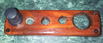
Was playing around with an alternative style for the front (inspired by the HD 90s/Orpheus) - this was just a bit to test the finish and different holes:

me8OPRi.png

But I don't really have the equipment/experience to quite pull the look off.

This has been while frustrating at times overall a very rewarding experience - I probably just had a massive grin on my face before posting this thread just listening to it all working with my test playlist.

EDIT: If anyone has pics, etc. of their own builds feel free to share - its been a great experience and I'm interested in what other people have come up with.
 
Last edited:
Man of Honour
OP
Joined
13 Oct 2006
Posts
92,063
Something slightly different - PCM2902 USB DAC soldered onto a breakout board

7smLCfv.jpg

SSOP-28 by hand is no fun even with flux and drag soldering (no idea yet if the chip survived the ordeal).

EDIT: It lives! (USB DAC)

XpT8Gx4.png

1O7ys8D.png

Audio quality isn't amazing (especially as I didn't have one of the voltage regulators required for "high performance" operation mode) - about on par with the quality from an "ok" realtek integrated or something but the main goal was to familiarise myself (and see if I could even solder a SSOP chip) before spending on anything more expensive.

EDIT: Having some problems with the microphone side of it - had a suspicion the capacitors were the wrong way around in the datasheet example though not sure if thats the problem.

EDIT2: Line in/Mic is messed up - not sure if something got damaged or it just doesn't have enough power due to the missing regulator, added one cap to help with power delivery on the DAC side and the audio quality improved immensely (I actually can't really hear any issues with it now) - with the high performance circuit it would probably sound pretty decent.

EDIT3: Jury rigged a LM317T in there on the USB DAC as a regulator (didn't have any joy with the 317LZ seemed to actually drop more voltage than the T) - not really very optimal (ugly hack job) but seems to have sorted out the issues - just about squeezing enough voltage out of it skipping the adjust circuitry. The input seems to only function as a line in without further changes. Sound quality is now respectable enough though the input side is a bit lacking.
 
Last edited:
Man of Honour
OP
Joined
13 Oct 2006
Posts
92,063
Don't think anyone does a single chip balanced DAC with USB controller :S not sure I want to get into building something like that :S (It looks quite advanced to get it all working properly).
 
Man of Honour
OP
Joined
13 Oct 2006
Posts
92,063
For a USB based balanced DAC looks like to do it proper i.e. better than 16bit/48KHz would need to pair something like TMS320C5533 and PCM1794A which involves a certain amount of software programming (the framework is provided so that side of it would be well within my capabilities) bit of a project to take on as a hobby though :S

EDIT: Looks like another option would be CM6631A into something like the PCM179x line.

EDIT2: Problem is by that point your into high end territory that really needs something more appropriate than a pseudo balanced op amp jobbie :S so might as well just chuck the money at a Gungnir, HDVD 800 or similar and/or matching amp.
 
Last edited:
Man of Honour
OP
Joined
13 Oct 2006
Posts
92,063
I was pondering speakers but I don't really have anywhere to properly use them at the moment and to do it proper means getting my head around all the enclosure acoustics issues, port tuning, etc.
 
Man of Honour
OP
Joined
13 Oct 2006
Posts
92,063
Yeah in some ways it's more time consuming and difficult I guess due to the extra materials and tools that are needed.

Some simple electrics with a soldering iron is a nice place to start like you have :)

I kind of regret dropping electronics now, most of my IT qualifications were obsolete 10 years ago whereas a lot of an electronics engineering degree (none the least covers a fair bit of computing also) are still meaningful today. Was struggling to be able to stay on top of studying for both courses though.

However my electronics lecturer at the time though absolutely brilliant at electronics was a total failure as a teacher - I think only 1 person passed (he already had degrees in maths and physics so had a head start) - so it wouldn't have likely produced much either :S
 
Man of Honour
OP
Joined
13 Oct 2006
Posts
92,063
This could be modified to work with the pseudo balanced amp idea to give a high performance pseudo balanced dac/amp combination:

http://users.abo.fi/jskata/JEDAC/

Talking a good £200 in parts for the whole lot and needing multi-layer pcb and a well engineering design to be really worth doing though - think I'll give it a miss for now.
 
Man of Honour
OP
Joined
13 Oct 2006
Posts
92,063
Yeah, £200 is a bit steep at this stage

Yeah, I'd happily spend the money if I thought I could get most of the performance out of those higher end parts but the reality is you need to be an experienced engineer (especially when it comes to ground design, etc.) to do them anything like justice on prototyping type PCBs and those kind of people wouldn't be building circuits like this on those type of PCBs anyhow :S

i.e. with the PCM1794 I'd probably struggle to top 100db SNR out of its possible ~137db whereas with the PCM2902 I can easily get the top end of its capabilities (around 96db).
 
Man of Honour
OP
Joined
13 Oct 2006
Posts
92,063
Oh **** was hurrying to get the enclosure for the final version of the amp drilled before having to leave for work earlier and managed to cut the panels the wrong way up (not that there is exactly a top and bottom but one looks better as the top than the other) and the LED hole is 1mm off level with the other holes :| only realised after I'd got all the connectors screwed in, etc. :S
 
Man of Honour
OP
Joined
13 Oct 2006
Posts
92,063
Got a couple of spares of the enclosure - they are quite useful - probably redo it when I've got some time - put it together just now and it works (better than the testing one as well) but seems the RCA inputs are reversed :S (not used this cable before so it might be the cable at fault).

Putting stuff together in a hurry + not enough sleep doesn't produce the best results lol.

EDIT: It is the cable that is made up wrong phew - bit bad as its not a cheapy one. (EDIT2: Easily "fixed" as the L/R markings are just a removable sleeve and the wiring doesn't make any odds which way around it is).

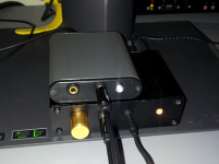
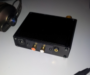
EDIT: As I ended up with the day off work couple of quick pics of how it looks - I'm not really happy though few things ended up out of alignment, etc. due to space constraints i.e. the RCA panel should be inside really so probably replace it with individual sockets as well as the case technically being the wrong way up also some of the spacing is off so as to leave the possibility of adding stuff in like source and gain switches, etc. if I feel like I need them:

qSn2fGv.png

yVY6HSt.png

The board itself is largely similar to the first pic though JST connectors, jumpers, etc. are gone and layout is better.
 
Last edited:
Man of Honour
OP
Joined
13 Oct 2006
Posts
92,063
While more luck than judgement (though I did spend awhile hand matching resistor values) got a dead even split to 1mv on the virtual ground this time :D (or atleast as precise as my fairly basic equipment can measure) - sits at exactly +/-6.333v unmoving under any load conditions I tested it with :D (which is enough to prevent clipping with the 8066 driving 300 ohm - would need a bit more with some other op amps).

Have to say while some question that virtual ground on its engineering merits sonically it seems to deliver and it easily (if you have heatsinks :S) handles upto about 60watts heh - think I'm using like less than 100th of that.
 
Last edited:
Man of Honour
OP
Joined
13 Oct 2006
Posts
92,063
I've left room to accommodate stuff like gain switching but still on the fence on that - I'm not sure on the technical side if there is any potential for damage, etc. but even IEMs run fine off it aslong as I turn the volume down without any frequency response issues I can hear (maybe a tiny amount to the bass). I'm using a gain of 6 which seems to work best over a range of headphones and I can't personally hear any quality loss between that and 11 using the 600s.

Tube amps have never really been my thing - I like a harsher "analytical" rather than warmer sound and prefer the bass from solid state.

Gonna put together a USB DAC (still based on the PCM2902) in the same enclosure to go with it though won't be my main audio source.

Quite tempted though to pickup an STX II seeing the chips they use in there and try putting some 8066s in :S
 
Last edited:
Man of Honour
OP
Joined
13 Oct 2006
Posts
92,063
^^ Not really given it much thought.

Had a bit of a play with the 2nd PCM2902 I'd bought over the weekend but looks like converting the design to be properly externally powered is beyond me right now :S its not really designed for it anyhow.

(Doing a little playing around with the original PCM2902 + the amp puts SNR at ~89dB which is why I'm a bit reluctant to go crazy on the pseudo balanced setup - some basic tests on the amp put THD @ 1KHz at 0.003% which is pretty good but the other results are a bit mixed, frequency response I'm having a hard time getting an accurate figure for with one channel seeming a bit off and crosstalk also having some issues getting an accurate figure for but generally seems to be around -70db).
 
Last edited:
Man of Honour
OP
Joined
13 Oct 2006
Posts
92,063
Ooops - course the amp + usb dac combo was ~89db as I was looping it for that test and the ADC is rated for 89db *facepalm*.

Forgot I'd done some bank holidays, etc. last month so got a bit of spare cash so decided as I'm not entirely happy with the results (aside from OCD about the case being "upside down") to redo it with a bunch of Nichicon FG series caps for the audio parts though sticking with the Panasonic FMs for the power supply - think I can improve the amp quite a bit as there are a few bits of wire between connectors I've since thought of ways to get rid of.
 
Back
Top Bottom