Hows my layout?

Associate
Joined
14 Jan 2011
Posts
91
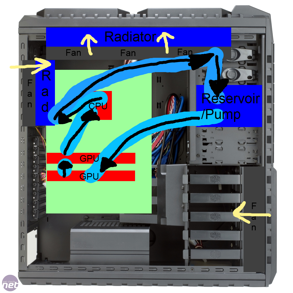
Got a load of stuff coming over the next few days to build my very first watercooling loop. :D

360 Rad in the top and a 120 in the rear should be enough, cooling both the CPU and both GPUs. I'm pretty confident about putting it all together but just wanted to see if you guys would take a look at the layout and tell me what you think.

Should I make the 120 in the back exhaust instead of intake, and would it be better having it go....

Pump/Res>GPU>GPU>RAD>CPU>RAD>Pump/Res?

I'm taking out the 2x200mm fans in the top that come with the HAF-X as I've seen that they just interfere with the rad fans, going to be switching one of the top ones to the front as they're quieter and move more air than the one that's there now, there's also the side fan that'll be an intake too. I'm also willing to stick a fan on the bottom drawing air in next to the PSU just for that bit of increased airflow but I'm not 100% on that yet.

So guys, whatcha think? (Excuse the rather crude drawing..)

LAYOUT_zps3eb64d73.png
 
i would go res/pump-cpu-240-120-gpu-gpu-back to res it would be a lot cleaner and neater
swap the 240,round and have the 120 on the back and the fan exhausting
 
So you're gonna have warm GPU liquid flowing into the CPU block?

Like Jokerster said, it makes almost no difference as the liquid is going to be flowing around the loop very quickly and doesn't just sit there collecting heat to take to the next component..

i would go res/pump-cpu-240-120-gpu-gpu-back to res it would be a lot cleaner and neater
swap the 240,round and have the 120 on the back and the fan exhausting

It's a 360 :P, I was going to have the inlet/outlet for the rad above the reservoir so I can hide a bit of slack in there so i'll be able to pull it out the front to fill it. Apart from the tubing that's going from the 120 to the 360 then to the res every other length of tubing is going to be quite short and tight anyway.

What if I mount the 120 sideways so theres an inlet at top and bottom instead of both at the bottom/top.. Would make tubing a lot easier I think.

Double Edit
Just drew it out to see what it'd look like and what you said actually does make it a lot neater. I can still hide a bit of slack behind the res coming from the GPUs. Thanks Josh.


Thanks for the input though.
 
Last edited:
So you're gonna have warm GPU liquid flowing into the CPU block?

this is actually irrelevant, the loop will reach equilibrium and with flow rates beign high enough it makes no difference if your cpu block comes after GPu blocks before them or after a rad as the circulating water will reach a steady state.

the science is explained here

In 99% of watercooling systems there is no "optimal" component ordering, EXCEPT that which minimizes tight bends and overall tubing length. This is not always true as there can be a significant difference (read: measurable) when dealing with extremely high heat loads, like those found in systems in which one or more components are actively cooled by a TEC. Because of water's high heat capacity, there is very little change in water temperature due to the heat dump from components that may be considered "parasitic" to the loop's most efficient operating conditions. What do I mean by this? In your case, this only really applies to the pump.

Example:

Specific heat of water (c) = 4.186 J/gram-°C

By definition 1 Joule (unit of energy) = 1 Watt-second (unit of power)

therefore, c = 4.186 W-sec/gram-°C

Meaning, if you pump "dumped" a modest 15W of heat into your loop:

Q = cm(ΔT) where Q is the heat added (15W), c is the specific energy of the material "receiving" the heat energy (water), m is the mass of the material, and delta T is the rise in temperature of the material.

Since this would ultimately depend on flow rate (to be given as g/sec, L/hr, gal/min or whatever other units you desire) we are going to simplify our example by assuming your flow rate is 2L/min:

(2L/min)(1 min/60 sec)(1000 g/1L) = ~42 g/sec (1L water = 1000 g by definition)

Q = cm(ΔT) => 15W = (42 g/sec)(4.186 W-sec/g-°C)(ΔT) -> ΔT = 0.08 °C

As you can see, certainly not a lot of temperature rise due to the pump alone. So assuming the water temperature entering the pump was 25°C exactly, this would mean that the outlet temperature from the pump would be 25.08°C. If the CPU (or any other block) was located such that the outlet of the pump directly feed it then the supply temperatures would be 25.08°C! (assuming that your tubing was a perfect insulator)

Try repeating this calculation with higher flow rates (3L/min, 4L/min, etc.) and you will see that in any case there is not much to be gained by sending the water from the pump through the radiator before any cooling block/device. In fact, due to the extremely small water temperature increase from to the pump I'm no so sure you would see ANY difference in radiator outlet temperature (a passive heatsink's ability to reject heat is directly proportional to the difference in temperature between the medium being cooled and the medium providing the cooling, in this case air at ambient).

Finally, since the GPU and CPU block locations are the only other real question, I can only provide you with the same advice. Using the equation above you can calculate the approximate rise in water temperature across the block (I say approximate because Q in the given equation can only be approximated from true processor power consumption since calculations, as provided, would have to assume that 100% of the heat from the processor is transmitted to the block and then to the water, which is untrue...). Then it's just a matter of determining which component you think needs that extra degree or two of cooling to perform best. At this point it's really a matter of preference and/or individual testing (which would require that you test the loop with each block individually installed, to remove the other as a competing variable, and then plotting the overclock results as a function of supply water temperature).

I hope I've at least partially answer your question. If not, here's the bottom line: I believe you will find that there is little to no performance difference to be achieve by ordering components in your loop. Instead, work to minimize flow resistance (smooth tubing bends and as little tubing used as possible).
 
Back
Top Bottom