Don
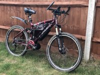
I have Multiple Sclerosis but I also love cycling. This causes me a bit of a problem as when exhaustion hits, it hits hard. I decided to convert my Saracen Ariel 3 to electric.
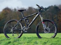
After considering various hub motors and the BBS01/02 range, I eventually settled on the BBSHD as having sufficient power for climbing hills when towing my son on his tag-along.
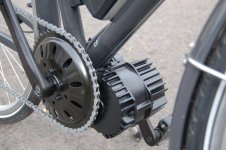
After doing lots of reading, I discovered that the BBSHD has a very large secondary recution gear casing that can cause some issues with fitment on bikes with wide chainstays. My bike is by no means a fat-bike but after taking advice I figured it was best to measure it. The secondary reduction gear is 68mm in radius. This picture is from another poster illustrating the issue.
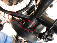
Hmm, it's not going to fit. It would be fouling the chainstay.
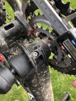
That's about how far I would need to offset the BBSHD to clear the chainstay.
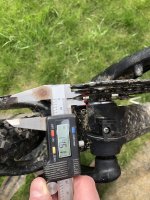
My BB is 68mm so I would need a BBSHD capable of fitting a 72mm BB as a bare minimum. Probably more like 75mm to give some clearance. This means getting the next size of BBSHD up.
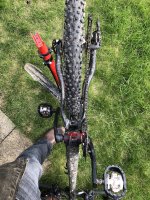
After taking some advice from the guys on the ever useful Pedelecs forum, I decided that a change of frame would be a better idea. So, armed with a shortlist of frames that I knew people had had success with I scoured eBay. Enter a 2009 Felt Compulsion 2 with knackered Equilink bearings.
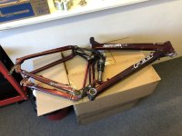
Loads of clearance here.

The first job was to sort out the bike's knackered bearings. I ordered a full set as well as a service kit for the shock and for my Rockshox Revelation forks. I didn't order the stupidly expensive Felt installation kit for the bearings, figuring I could MacGyver something up.
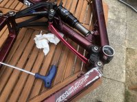
Some threaded rod and various sockets and nuts work well as bearing pullers and presses. This is the Equilink bar.

Chainstays removed.
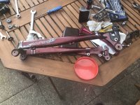
More sockets, spanners, bolts, and nuts to remove the old bearings.
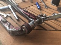
In reverse to install the new ones. I used the old bearings as the washers for the makeshift press.
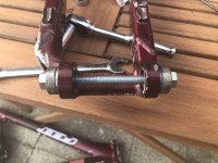
Another franken-puller. I knew there was a use for all of those imperial sockets I never use!
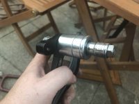
More bearings being installed.
I didn't photograph the fork and shock rebuilds as my hands were covered in suspension oil and float fluid. It was pretty easy TBH. The only issue I had was the initial seal kit I'd ordered for the Revelations was the wrong one.
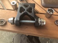
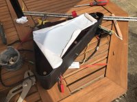
The first Issue I had with the new frame was that the triangle was too small to fit any of the off-the-shelf dolphin or shark packs easily. I decided to build my own pack because I'd never done it before and I like making things hard for myself.
First I laid the frame on some cardboard and drew the triangle. Sorry for the crappy picture.

I cut out the cardboard and laid it on some MDF board.

And made a jig for my battery box.
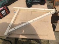
I used acrylic sheet to make the edges of the triangle box. I wanted to do it this was so I could make some nice curves for the corners. Sharp edges are going to be dangerous. I used some 2.5" waste pipe for the radius jig and my toaster to heat the acrylic.

There we go. Corners all made. Just need to cut the excess off and glue it.
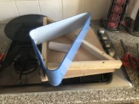
I love this stuff. I used 3mm ply-wood for the sides of the box. Mainly for strength and also because it's what I had lying around. I sealed it with marine primer and plastidip coating.
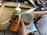
On to the battery. I wanted to go for a 52V system for the extra power it offers. I wasn't too fussed about range so initially decided on a 14S4P system (56 x 18650 cells). After drawing up the battery box in LibreCAD I saw that I could easily fit 70 cells in for the 14S5P system and so went for this instead. Mainly due to it putting less stress on individual cells.

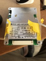
This is the BMS I'm using. I know very little about these things but this one was recommended on the Pedelecs forum. I defer to their superior knowledge.
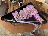
I ordered 74 (I figured correctly that I would destroy a few) Samsung 30Q (3000mAh 20A) cells from nkon.nl and laid them out with the BMS in the partially finished battery case. This is the arrange ment I settled on. However in the final build I rotated the 2 groups at the bottom of the triangle by 90 degrees.
I need to weld 70 x 18650 batteries together in a 14S4P configuration. I could just buy a battery welder but where's the fun in that? And, like I said before, I like making things hard for myself.
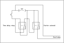
This is my circuit design. I'm going to use a motorcycle battery, a starter solenoid, and a time-delay relay.
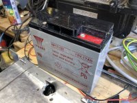
Bike battery. A cheapo NP17-12 but should be good for 200 amps.
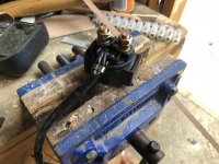
Solenoid. I'm hoping it can cope with the 200 amps or so I will be drawing for 0.1s but if it can't I'll bag a bigger one.
Post script: It couldn't and lasted about 10 welds. I bagged a much bigger one that continued working.
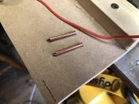
Heads cut off some copper nails. These will act as the electrodes.
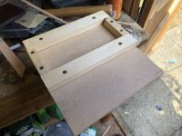
I figured I couldn't just have the battery floating around on the bench. I threw together a base.
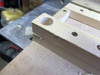
Hole for the momentary button.
Here's the timer circuit. Pretty inexpensive little thing. I can stay closed from between 0.15s and 1 hour. We're going to use the 0.15s setting.
This is the relay: https://www.ebay.co.uk/itm/12V-DC-Delay-Relay-250v-AC-Turn-on-Delay-Turn-off-Switch-Module-with-Timer-UK/332588356826?ssPageName=STRK:MEBIDX:IT&_trksid=p2057872.m2749.l2649
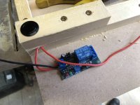
I wanted to test the two relays so wired them together and yes, they work.
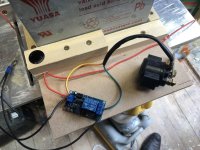
I used a small piece of steel bar to hand the solenoid from the battery. The other wire is the +ve connection for the coil side of the solenoid.
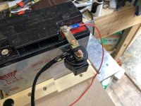
It works!
Here's a vid of it working:
Parts list:Momentary push button:
https://www.amazon.co.uk/gp/product/B01AW4FS00/ref=oh_aui_detailpage_o05_s00?ie=UTF8&psc=1
Starter solenoid:
https://www.amazon.co.uk/gp/product/B015H1URDQ/ref=oh_aui_detailpage_o07_s00?ie=UTF8&psc=1
Copper nails:
https://www.amazon.co.uk/gp/product/B00MK9AUR2/ref=oh_aui_detailpage_o08_s00?ie=UTF8&psc=1
Heavy-duty cable:
https://www.amazon.co.uk/gp/product/B007KM5MNG/ref=oh_aui_detailpage_o09_s00?ie=UTF8&psc=1
NP17-12 12V battery:
https://www.ebay.co.uk/itm/Yuasa-NP17-12-Rechargeable-lead-acid-battery-12-volt-17Ah/162894646918?ssPageName=STRK:MEBIDX:IT&_trksid=p2057872.m2749.l2649
60A choc-block
https://www.ebay.co.uk/itm/12-Way-Connectror-Strip-3A-60A-Electrical-Chock-Block-Wire-Terminal-Connection/123000115084?ssPageName=STRK:MEBIDX:IT&var=423441514332&_trksid=p2057872.m2749.l2649
Timer relay:
https://www.ebay.co.uk/itm/12V-DC-Delay-Relay-250v-AC-Turn-on-Delay-Turn-off-Switch-Module-with-Timer-UK/332588356826?ssPageName=STRK:MEBIDX:IT&_trksid=p2057872.m2749.l2649
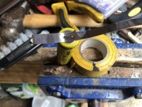
I set about welding my cells together.
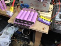
Gradually adding them in groups of 5 and using hot-glue to hold the pack together.
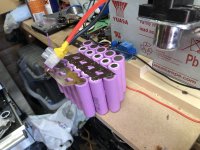
Unfortunately, I blew a hole through the -ve terminal of a couple of cells but didn't notice until I'd added several more to the pack. This meant that I had to cut the bad cells out and re-do the welding. Good practice I guess for when I have to do it when a cell fails naturally.

More added.
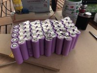
Pack finished and checking the voltage. 51.1V. Spot on as when I measured each cell individually they were coming out at 3.65V each which is the normal storage voltage for 18650s. Fully charged they will be 4.2V giving 58.8V.
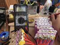
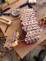
Soldered the balance wires from the BMS to each cell group on the top.
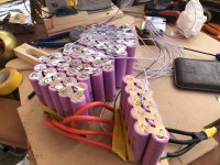
And then the rest on the bottom.
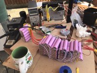
I cracked out the 60V PSU to give the pack its first charge. Only up to 4.1V per cell to start with. This was pretty scary to be honest.
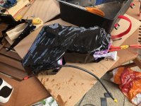
Heat-shrink on.
YES! IT FITS!.
I routed some grooves at the top of the battery box to attach Velcro straps for additional security. The other thing you can just see at the bottom of the box is a LunaCycle power switch. I didn't like the idea of having a massive battery without a power switch and this one is fully solid state.
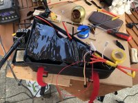
To finish off the box I cut some acryclic sheet to mount to the sides. This is transparent and the same colour as the bike. It looks quite nice I think. The Seakon connector you see on the right is the charging port. I like Speakon connectors because you can't wire them backwards and they are very hard wearing.
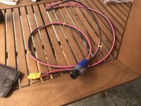
This is the charging cable. A Speakon connector on one end and an XT90AS on the other.
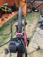
Battery built, I turned my attention to the bike and had a go at a test fit of the BBSHD. It fitted really well.
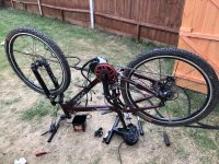
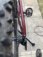
Chainline looks OK but it was throwing the chain when on the largest rear cog. This means that I need to get the chain a bit closer in to the BB. I cracked out the angle grinder and took 2mm off the BB on the chain side. This brought the chain back in line and now all gears can be used. I also mounted a gutted front deraileur that was set to a fixed position to help if there was any chance of the chain coming off. Pics later on of the final chainline.
Doh! Bringing the BBSHD closer in had the effect of making the sprocket foul the chainstay. Oh well, a little time with the angle grinder soon sorted that issue out.
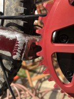
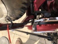
There we go. That part of the chainstay was additional external strengthening. I've not cut in to the tube.
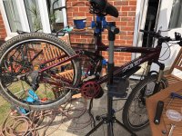
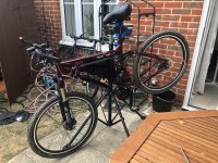
Bike on the stand. You can see here that I've flipped the shock upside down. This gives a little more room for the battery box.
Battery out of the box and box mounted to the bike. It fits nice and snug. This was a test to see where I can route all my wires.
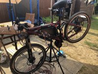
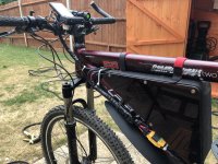
Other side of the bike showing the battery box, power switch, and charging port. I have a waterproof cover to go over the charging port.
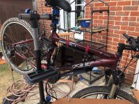
I wanted a more accurate measurement of how much current I was pulling from the battery as well as a more accurate voltmeter (the BBSHD doesn't read above 56V). I had one of these knocking around from testing current draw of multicopters. It seemed to fit the bill.

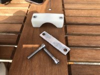
I knocked up a quick bracket to mount the watt meter to the stem. A bit of nylon block, some bolts, and some ally.
Mounted on the stem. There is Velcro under the meter but I added a couple of cable ties for extra security.
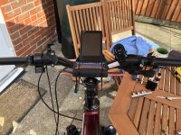
I flipped the display 180 degrees on its mount. This makes it stick out a bit more but gave me more space to mount the watt meter.
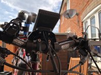
Battery fitted inside the box and starting to connect cables.
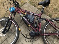
Next up was to fit the brake cutouts. I have hydraulic brakes and so had to use a different kit rather than the levers that come with the BBSHD. The kit comprises of a small magnet and a hall sensor. I drilled a hole in the lever to bolt the magnet.
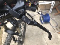
Fitted.
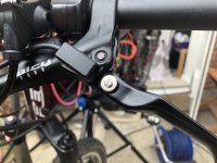
There we go. pretty much all finished. I just need to use some cable sheathing on the power wires to tidy it up and we're good to go.
I weighed the bike as it is and it came in at 25.1kg which is lighter than I was expecting. Weight is very well centralised and so it does actually feel like a bicycle to wheel about, rather than a top-heavy monster.
First power on. Yes, I know the chain and pedals are missing. I figured it was best to test it without the possibility of it spinning the back wheel at 50mph and destroying the bike and bike stand.
You can see here the arrangement of the various controls on the bars. I opted to mount the throttle on the left bar, mainly due to space issues on the right with the gear selector pod. The controls for the BBSHD are also mounted on the left bar. The lever above them is the lockout for my forks which I flipped upside down to give me more space. The rubber thing on the right is the mount for my front light.
https://i.imgur.com/Pg3bQCQ.mp4
Chainline is OK. Not the best but good enough that it’s not going to throw the chain in 1st.
Video of the shifting. I can use all 9 gears. My wheel isn't bent by the way. It's the tyre. New ones on the way.
Cables wrapped up.
Mudguard on
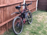
Ready to go.
It rides beautifully. Loads of power. I'd say it's got significantly more power than your average 50cc scooter. It's very smooth too with its power delivery. I've yet to ride it in anger or for any distance but will be doing so in the coming weeks. I'll post up some video of my thoughts another time.

After considering various hub motors and the BBS01/02 range, I eventually settled on the BBSHD as having sufficient power for climbing hills when towing my son on his tag-along.

After doing lots of reading, I discovered that the BBSHD has a very large secondary recution gear casing that can cause some issues with fitment on bikes with wide chainstays. My bike is by no means a fat-bike but after taking advice I figured it was best to measure it. The secondary reduction gear is 68mm in radius. This picture is from another poster illustrating the issue.

Hmm, it's not going to fit. It would be fouling the chainstay.

That's about how far I would need to offset the BBSHD to clear the chainstay.

My BB is 68mm so I would need a BBSHD capable of fitting a 72mm BB as a bare minimum. Probably more like 75mm to give some clearance. This means getting the next size of BBSHD up.

After taking some advice from the guys on the ever useful Pedelecs forum, I decided that a change of frame would be a better idea. So, armed with a shortlist of frames that I knew people had had success with I scoured eBay. Enter a 2009 Felt Compulsion 2 with knackered Equilink bearings.

Loads of clearance here.

The first job was to sort out the bike's knackered bearings. I ordered a full set as well as a service kit for the shock and for my Rockshox Revelation forks. I didn't order the stupidly expensive Felt installation kit for the bearings, figuring I could MacGyver something up.

Some threaded rod and various sockets and nuts work well as bearing pullers and presses. This is the Equilink bar.

Chainstays removed.

More sockets, spanners, bolts, and nuts to remove the old bearings.

In reverse to install the new ones. I used the old bearings as the washers for the makeshift press.

Another franken-puller. I knew there was a use for all of those imperial sockets I never use!

More bearings being installed.
I didn't photograph the fork and shock rebuilds as my hands were covered in suspension oil and float fluid. It was pretty easy TBH. The only issue I had was the initial seal kit I'd ordered for the Revelations was the wrong one.

The first Issue I had with the new frame was that the triangle was too small to fit any of the off-the-shelf dolphin or shark packs easily. I decided to build my own pack because I'd never done it before and I like making things hard for myself.
First I laid the frame on some cardboard and drew the triangle. Sorry for the crappy picture.

I cut out the cardboard and laid it on some MDF board.

And made a jig for my battery box.

I used acrylic sheet to make the edges of the triangle box. I wanted to do it this was so I could make some nice curves for the corners. Sharp edges are going to be dangerous. I used some 2.5" waste pipe for the radius jig and my toaster to heat the acrylic.

There we go. Corners all made. Just need to cut the excess off and glue it.

I love this stuff. I used 3mm ply-wood for the sides of the box. Mainly for strength and also because it's what I had lying around. I sealed it with marine primer and plastidip coating.

On to the battery. I wanted to go for a 52V system for the extra power it offers. I wasn't too fussed about range so initially decided on a 14S4P system (56 x 18650 cells). After drawing up the battery box in LibreCAD I saw that I could easily fit 70 cells in for the 14S5P system and so went for this instead. Mainly due to it putting less stress on individual cells.

This is the BMS I'm using. I know very little about these things but this one was recommended on the Pedelecs forum. I defer to their superior knowledge.

I ordered 74 (I figured correctly that I would destroy a few) Samsung 30Q (3000mAh 20A) cells from nkon.nl and laid them out with the BMS in the partially finished battery case. This is the arrange ment I settled on. However in the final build I rotated the 2 groups at the bottom of the triangle by 90 degrees.

I need to weld 70 x 18650 batteries together in a 14S4P configuration. I could just buy a battery welder but where's the fun in that? And, like I said before, I like making things hard for myself.
This is my circuit design. I'm going to use a motorcycle battery, a starter solenoid, and a time-delay relay.

Bike battery. A cheapo NP17-12 but should be good for 200 amps.

Solenoid. I'm hoping it can cope with the 200 amps or so I will be drawing for 0.1s but if it can't I'll bag a bigger one.
Post script: It couldn't and lasted about 10 welds. I bagged a much bigger one that continued working.

Heads cut off some copper nails. These will act as the electrodes.

I figured I couldn't just have the battery floating around on the bench. I threw together a base.

Hole for the momentary button.

Here's the timer circuit. Pretty inexpensive little thing. I can stay closed from between 0.15s and 1 hour. We're going to use the 0.15s setting.
This is the relay: https://www.ebay.co.uk/itm/12V-DC-Delay-Relay-250v-AC-Turn-on-Delay-Turn-off-Switch-Module-with-Timer-UK/332588356826?ssPageName=STRK:MEBIDX:IT&_trksid=p2057872.m2749.l2649

I wanted to test the two relays so wired them together and yes, they work.

I used a small piece of steel bar to hand the solenoid from the battery. The other wire is the +ve connection for the coil side of the solenoid.

It works!
Here's a vid of it working:
Parts list:Momentary push button:
https://www.amazon.co.uk/gp/product/B01AW4FS00/ref=oh_aui_detailpage_o05_s00?ie=UTF8&psc=1
Starter solenoid:
https://www.amazon.co.uk/gp/product/B015H1URDQ/ref=oh_aui_detailpage_o07_s00?ie=UTF8&psc=1
Copper nails:
https://www.amazon.co.uk/gp/product/B00MK9AUR2/ref=oh_aui_detailpage_o08_s00?ie=UTF8&psc=1
Heavy-duty cable:
https://www.amazon.co.uk/gp/product/B007KM5MNG/ref=oh_aui_detailpage_o09_s00?ie=UTF8&psc=1
NP17-12 12V battery:
https://www.ebay.co.uk/itm/Yuasa-NP17-12-Rechargeable-lead-acid-battery-12-volt-17Ah/162894646918?ssPageName=STRK:MEBIDX:IT&_trksid=p2057872.m2749.l2649
60A choc-block
https://www.ebay.co.uk/itm/12-Way-Connectror-Strip-3A-60A-Electrical-Chock-Block-Wire-Terminal-Connection/123000115084?ssPageName=STRK:MEBIDX:IT&var=423441514332&_trksid=p2057872.m2749.l2649
Timer relay:
https://www.ebay.co.uk/itm/12V-DC-Delay-Relay-250v-AC-Turn-on-Delay-Turn-off-Switch-Module-with-Timer-UK/332588356826?ssPageName=STRK:MEBIDX:IT&_trksid=p2057872.m2749.l2649

I set about welding my cells together.

Gradually adding them in groups of 5 and using hot-glue to hold the pack together.

Unfortunately, I blew a hole through the -ve terminal of a couple of cells but didn't notice until I'd added several more to the pack. This meant that I had to cut the bad cells out and re-do the welding. Good practice I guess for when I have to do it when a cell fails naturally.

More added.

Pack finished and checking the voltage. 51.1V. Spot on as when I measured each cell individually they were coming out at 3.65V each which is the normal storage voltage for 18650s. Fully charged they will be 4.2V giving 58.8V.

Soldered the balance wires from the BMS to each cell group on the top.

And then the rest on the bottom.

I cracked out the 60V PSU to give the pack its first charge. Only up to 4.1V per cell to start with. This was pretty scary to be honest.

Heat-shrink on.

YES! IT FITS!.
I routed some grooves at the top of the battery box to attach Velcro straps for additional security. The other thing you can just see at the bottom of the box is a LunaCycle power switch. I didn't like the idea of having a massive battery without a power switch and this one is fully solid state.

To finish off the box I cut some acryclic sheet to mount to the sides. This is transparent and the same colour as the bike. It looks quite nice I think. The Seakon connector you see on the right is the charging port. I like Speakon connectors because you can't wire them backwards and they are very hard wearing.

This is the charging cable. A Speakon connector on one end and an XT90AS on the other.

Battery built, I turned my attention to the bike and had a go at a test fit of the BBSHD. It fitted really well.

Chainline looks OK but it was throwing the chain when on the largest rear cog. This means that I need to get the chain a bit closer in to the BB. I cracked out the angle grinder and took 2mm off the BB on the chain side. This brought the chain back in line and now all gears can be used. I also mounted a gutted front deraileur that was set to a fixed position to help if there was any chance of the chain coming off. Pics later on of the final chainline.

Doh! Bringing the BBSHD closer in had the effect of making the sprocket foul the chainstay. Oh well, a little time with the angle grinder soon sorted that issue out.

There we go. That part of the chainstay was additional external strengthening. I've not cut in to the tube.

Bike on the stand. You can see here that I've flipped the shock upside down. This gives a little more room for the battery box.

Battery out of the box and box mounted to the bike. It fits nice and snug. This was a test to see where I can route all my wires.

Other side of the bike showing the battery box, power switch, and charging port. I have a waterproof cover to go over the charging port.

I wanted a more accurate measurement of how much current I was pulling from the battery as well as a more accurate voltmeter (the BBSHD doesn't read above 56V). I had one of these knocking around from testing current draw of multicopters. It seemed to fit the bill.

I knocked up a quick bracket to mount the watt meter to the stem. A bit of nylon block, some bolts, and some ally.

Mounted on the stem. There is Velcro under the meter but I added a couple of cable ties for extra security.

I flipped the display 180 degrees on its mount. This makes it stick out a bit more but gave me more space to mount the watt meter.

Battery fitted inside the box and starting to connect cables.

Next up was to fit the brake cutouts. I have hydraulic brakes and so had to use a different kit rather than the levers that come with the BBSHD. The kit comprises of a small magnet and a hall sensor. I drilled a hole in the lever to bolt the magnet.

Fitted.

There we go. pretty much all finished. I just need to use some cable sheathing on the power wires to tidy it up and we're good to go.
I weighed the bike as it is and it came in at 25.1kg which is lighter than I was expecting. Weight is very well centralised and so it does actually feel like a bicycle to wheel about, rather than a top-heavy monster.

First power on. Yes, I know the chain and pedals are missing. I figured it was best to test it without the possibility of it spinning the back wheel at 50mph and destroying the bike and bike stand.
You can see here the arrangement of the various controls on the bars. I opted to mount the throttle on the left bar, mainly due to space issues on the right with the gear selector pod. The controls for the BBSHD are also mounted on the left bar. The lever above them is the lockout for my forks which I flipped upside down to give me more space. The rubber thing on the right is the mount for my front light.
https://i.imgur.com/Pg3bQCQ.mp4
Chainline is OK. Not the best but good enough that it’s not going to throw the chain in 1st.

Video of the shifting. I can use all 9 gears. My wheel isn't bent by the way. It's the tyre. New ones on the way.
Cables wrapped up.

Mudguard on

Ready to go.
It rides beautifully. Loads of power. I'd say it's got significantly more power than your average 50cc scooter. It's very smooth too with its power delivery. I've yet to ride it in anger or for any distance but will be doing so in the coming weeks. I'll post up some video of my thoughts another time.

Last edited:


 Downhill specific wheels will probably be more suitable.