Phanteks Luxe Tempered Glass

Pump Bracket Modding

So out came the pump bracket so I could put two slots in it. This has allowed me to run the power and data cable behind the bracket to clean it up. So out came Mr Dremel after a liberal application of masking tape. I need to anchor the cables in the lower drive bay area (the one I removed for the pump), but I will do this after I have converted to ridged tube, just in case I need to re-do it.


31462788021_b7e64fe439_c.jpg


31206473190_c1462d7574_c.jpg


31463790301_f0aca8e656_c.jpg


It is a touch on the tight side, so I might have to make the slots a little deeper.
 
Lets plan the Fans!

So I have decided to add an additional 240 Rad in the basement of the case. I have an improvement to the top Rad planned (more on that in a post coming up) however with the plan to add a GTX 1070 down the road, I felt it would be prudent to upgrade my radiator surface area. There is loads of room to add this without getting in the way and it’s not like I’m going to use the basement area for anything else!

So after giving it some thought i have settled on the following fan configuration:

30769445783_4042e1e1cf_z.jpg


The two front 140mm fans will pull cool air into the case
The rear 140 will exhsaust air out of the case
The 3 120mm fans on the top Rad are configured in PUSH, pushing cool air into the case, not ideal but due to Rad thickness this was the only possible configuration.
the 2 120mm fas on the bottom rad will be configgered in PULL to exhaust air out of the cast

this gives me a reasonably balanced setting, favouring slightly on the positive side. the rad fans normal spin slower than the case fans the way I have them configured.

I have a 6 way PWM splitter coming so I can run them all off the same header and run them off the same speed curve. I have also switched over to controlling the pump and Rad fan’s via water temperature after some testing which is much easier on the ears.
 
aquasuite

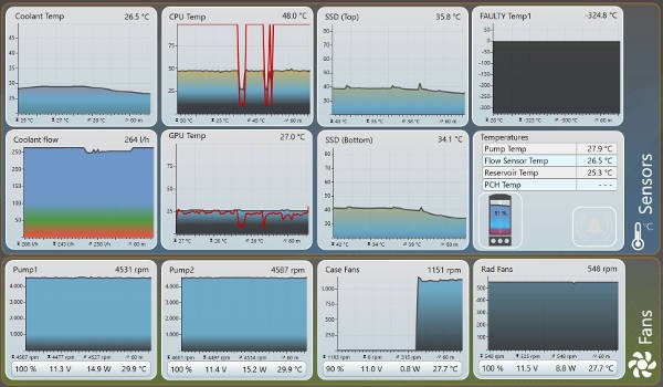
I have setup a new aquasuite dashboard to give me quick access to all fan related goodness, at the moment I have two 1080P monitors, when i get an 1440P ultrawide i will retain one of them to display the dashboard (i plan to mount this above the main display.

30740370314_7d7e2cc536_b.jpg


need to correct the CPU Core names....

I am now controlling the Rad fans and pump via water temperature, this is useful as it is completely independent of the OS and Hardware monitor, so if i get a system lockup it all runs at the speed it should.

31581765795_b593a48571_b.jpg


when the system is idle, the only thing i can hear is the PSU fan (i will fix that soon), during gaming only a little louder but very comfortable considering its now on my desk and not the floor.
 
Looking good. Controlling by water temp is the best idea as it doesn't change so rapidly as CPU temp. As you say, it's good that it will also work even if Windows goes belly-up.

Couple of things that might help you.

If you right click on a chart and click 'Settings'. At the bottom of the 'Display' tab you can change the time interval for a chart. That way you can have it show you up to 60 minutes of data rather than the default of 3.

You can layer charts - as I'm assuming you've discovered already by the look of that CPU temp chart. That way, if you get the axis right (0-100) you can put the load as well as the temperature on the same chart as I've done for CPU and GPU here:


You have to turn off the title and axis display and make the 'Background opacity' zero to stack them.

The other thing you may want to do is see what effect the pump speed has on your temps as it may be very little. If so, you may be able to find the fastest speed that is silent and fix it at that - or have it on a "panic" curve. That is, one that is the same speed until it gets to a temperature you're uncomfortable with (eg 40°C) and then jumps to 100%.
 
So let’s void whatever warranty the PSU had left

Disclaimer – opening up a PSU can be extremely dangerous, don’t do this unless you know the risk.

So I am sick with my PSU fan only running at one speed form what I can tell. It’s annoying with the system is at ideal and it’s still the loudest part of this rig when I game. If I’m really pushing the system then I don’t mind fan noise.

so my plan is to swap the fan out with a spare 3pin 140mm I have, but with a twist. I want to control the fan speed with the aquaero, but I need to get a baseline first.

31608082435_9da8f0e137_c.jpg


below you can see where I have attached two temperature sensors with blue masking tape (this is a temporary solution). I plan to run the system at full load to see how hot it gets.

31608082455_30cc4fea1b_c.jpg


And the test setup, I plan to run Prime Small FFT and FurMark to load the PSU as much as possible, I don’t have a clamp meter so i can’t check how much power I’m actually pulling

30798197113_63d328c05a_c.jpg


So after two hours of this loading test, the internals of the PSU are sitting at 47 and 45C. considering these units are rated to work at 50C ambient temperatures, i think i have loads of head room. Using a strobe it looks like the fan is stuck at 800RPM
 
Last edited:
Fixing the leak – well almost.

As mentioned previously the Rad doesn’t have standard spacing’s, so there are big gaps between the fans and an even bigger gap on each end. one of the reasons I feel I have lost a lot of cooling performance is that the air is just escaping around the edges of the Rad and not Travailing thought it.My previous setup had shrouds on both sides to prevent air escaping

31570726776_67519f4034_c.jpg


that is going to leak bad.....

so I got a gasket of sorts laser cut to help seal these gaps off, it’s not perfect and I plan to add a thin neoprene seal around the edges but I feel it’s a big improvement

30798197473_27b50bbfa7_c.jpg


so running a quick load test produces similar core temperatures to previous tests (74/75C), however it’s a lot hotter in the room today (probably a good 5C hotter). But what was interesting the water temperatures took almost a full 2 hours to get up to 30C, where they stabilised, this was happening reasonably quickly before the installation of the acrylic gasket was added.

This was however with FurMark running as well, with my GPU maxing out at 70C, so that can’t have helped the situation.

31492651661_9a0d1d9725_c.jpg
 
Last edited:
Dynamic PSU Cooling

So after I worked out that the internals (heatsinks surface) temperatures hit 47C under maximum load (100% CPU and GPU) I have permanently attached a temperature sensor on the internal of the PSU to one of the heatsinks. I used arctic silver thermal adhesive (which is a two part epoxy) to secure the sensor, i made a bit of a mess and needed to have two goes at it, but it won’t go anywhere now.


30788523194_3ff709d534_c.jpg


30819812813_c9035707fd_c.jpg


31630100165_322eb775f0_c.jpg
[/url]

So out with the old and in with the new. The only reason I’m changing this is to get a standard 3pin header, however the case fan I’m using is much quieter than the PSU one at the same speeds

31257763640_8387050b4b_c.jpg


And a quick check shows it’s all working. I have a valid temperature reading, the fan works and can be completely silent. I plan to set up a fan curve so that fan spins at around 800 RPM @ 50C, with the speed as low as I can until it gets to around 35C.

31592915616_36a5c60759_c.jpg
 
Sometimes to more forwarded, you need to tear it all down

So all my PETG Tube and fittings have arrived and I plan to pipe this all up over the Christmas brake so it was time to rip it all apart and rebuild it.

Draining the system is so much easier now I have installed a drain

31692450026_8373676918_c.jpg


31357168940_574e3e8d87_c.jpg


I have also upgraded the Pump with the EK Heatsink, this was mostly driven by how I would need to mount it and to see if I could reduce the noise levels due to the anti vibration mounts, as now my PSU fan is silent I can hear the pump again.

31357169390_ab71f2a176_c.jpg


31614500351_f9fe4a2f0d_c.jpg


So I did a test fit of the 240 Rad to get an idea of clearance to ensure that it will all be ok. and it looks great and all fits ok, ther is plenty of room above the pump for the fittings and the upper drive bay will be able to removed and installed with no problem. I will need to re-home the aquaero but I have a good idea where I can put that, I have plenty of room at the side of and above the 240 Rad for cables so this hopefully should work out good..

31692448956_f384115c8e_c.jpg


30920135653_3e5d2c0942_c.jpg


So below is close to the final config of the rad / pump area. I will add another 90 fitting to the pump output to make fitting the tube easer, I plan to bend and install the Tube before I mount this in the case, this will be my first bend as its out of the way so if I mess it up a bit it won’t matter to much.

I have also moved the water temperature sensor off the pump, I plan to fit a second one just after the CPU so I will have two readings for water temperature.

30888454904_50bfb7e358_c.jpg
 
"Draining the system is so much easier now I have installed a drain": I can manage to spill mine despite the drain I fitted. Talented, me! :p :D

Arctic Silver adhesive looks like a good permanent solution. For reference, the removable solution is Kapton tape - or a cheap Chinese imitation of it. It's the yellow tape (roll looks bronze) with adhesive that doesn't turn to goo when the heat warms up.

"I have also moved the water temperature sensor off the pump, I plan to fit a second one just after the CPU so I will have two readings for water temperature.": You should find that both readings are about the same (give or take a few degrees for the inaccuracy of the sensors) as the temperature of the loop will equalise. No harm for redundancy reasons, just don't expect them to be very different - like I did.

"I will add another 90 fitting to the pump output to make fitting the tube easer": Could you not just rotate the pump 90°? Or do you mean to direct the output upwards.
If you spun the pump 90° clockwise (looking from above) you could put the 90° bend in the tubing at a point that it's most convenient for getting to the next connection.
 
de-gunking time + more pump bracket mods

I have striped out all the water-cooling parts and given them a good clean. I cleaned out the radiator with a 50:50 vinegar solution but also had to resort to descaling solution to shift the worst of it. the CPU block was quite gunked up with crud which I cleaned out and gave it a good cleaning with Isopropyl Alcohol. I have also cleaned up the CPU IHS and re-applied the thermal compound.

the radiator has also been sanded down and re-painted to remove a lot of imperfections, it looks supper clean now and colour matches well with the case.

31822741665_7365639105_c.jpg


31675536812_62a00c0935_c.jpg


The reservoir bracket has also come out again. I have made the slot for the top SSD cables slightly deeper and also removed the bottom inch of the plate to allow clearance for the tube form the reservoir to pump.

31675536642_1f0bd4e3ce_c.jpg


Now that the radiator has been cleaned up, I have added a thin layer of neoprene around the gasket I got made to ensure all the air goes though the radiator and doesn’t leak around it.

31450039400_0649e1bcc4_c.jpg
 
Last edited:
Finish and colour match on that rad looks good. Some 9f the fins ate a bit bent but you'll never see them and I'd challenge anyone to measure a meaningful difference in temperature as a result.
 
Some of the fins ate a bit bent but you'll never see them and I'd challenge anyone to measure a meaningful difference in temperature as a result.

I am the second owner of this Rad, and it has been thought at least 3 builds whilst it was in my hands, a couple of bent finds shouldn’t have any effect.
 
So let’s start bending

I was quite happy with my first bending attempts, For the pump to Rad tube i had to do a full 90 with a small kink as the outlet of the pump and inlet of the Rad where not quite in line. However it is rock solid and there is no way this will pop out accidently,

I did overhead the tube slightly during this bend so the tube bubbled a little, but as this is out of the way there is no issue with this.

30982009844_9e4b6a08e9_c.jpg


I got this mounted in the basement of the case and all nice and secure

And then it went wrong a bit, i attempted a complex composite bend from the rear most Rad fitting to the outlet of the CPU block which required two 90 bends on-top of each other.

I wound up going though two tubes attempting this, melting some tube to the bending tool, and getting the bending rubber stuck twice to the point it is no longer usable, and chopped in Half. However I’m ticking this up to a learning experience, i have a good feel of when I should bend and how quickly as my first two bends attempting this where normally find. I plan to revert back to my original layout of tubing which should space out the bends significantly making it a bit easier.

30986217984_2d8abdf7f1_z.jpg
 
Didn't I post in your loop plan thread about using olive oil on the insert... ;)

Yep, and this is what I did. My issue was that I was being to ambitious with it. With 2 tight 90 bends on top of each other, so I wound up under heating as I didn't want the soften the previous one, or over heating and it going to mush.
 
More Bending

So after the Christmas fun it was time to get back to the project. after some thought and advice (thanks Smffy) i drenched the bending tube in olive oil and took my time with each bend, like sooooo slow. The more I did the better it got. I ditched the XSPC bending tool as I just couldn’t get on with it.

31128267783_84e686b1b7_b.jpg


Then it was time for the big bend, this was a 700mm run and I only had one 1m tube to attempt this with, it was also blind due to the location of the pump. In the end it was easier than expected and probably the best bending job of the lot.

31789917672_1068b2bb17_b.jpg


I have two tubes left so I might have another go at the front most tube form Rad to CPU block, however I am planning to add a water cooled GPU in the loop, so might just wait until then. not perfect but mostly happy with it.

now its on leak test, I will need to strip out the CPU block as its gunked up quite a bit during the leak test, I plan to cycle the loop with distilled water two more times and then add the coolant I will use.

31128267653_426345fcea_b.jpg


31564330880_32caa68ac6_b.jpg
 
Last edited:
Back
Top Bottom