Project:U2-UFO

Associate
Joined
10 May 2010
Posts
272
Location
Hampshire
I have finally decided to put a build log together after many months of reading all of the ones in project logs.

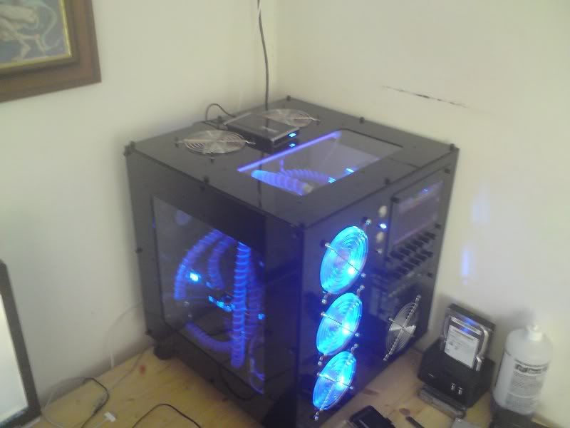
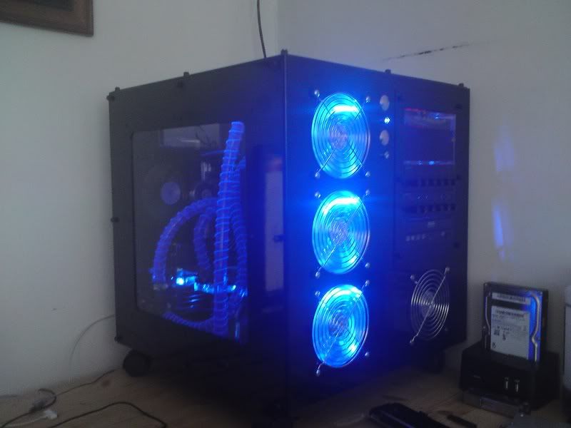
I initially had my U2 case built with water cooling in place. It had an i7 920 with ASUS P6 deluxe board and a watercooled 295 card. The motherboard was not water cooled and it ticked along quite nicely at about 4 GHz on the CPU.
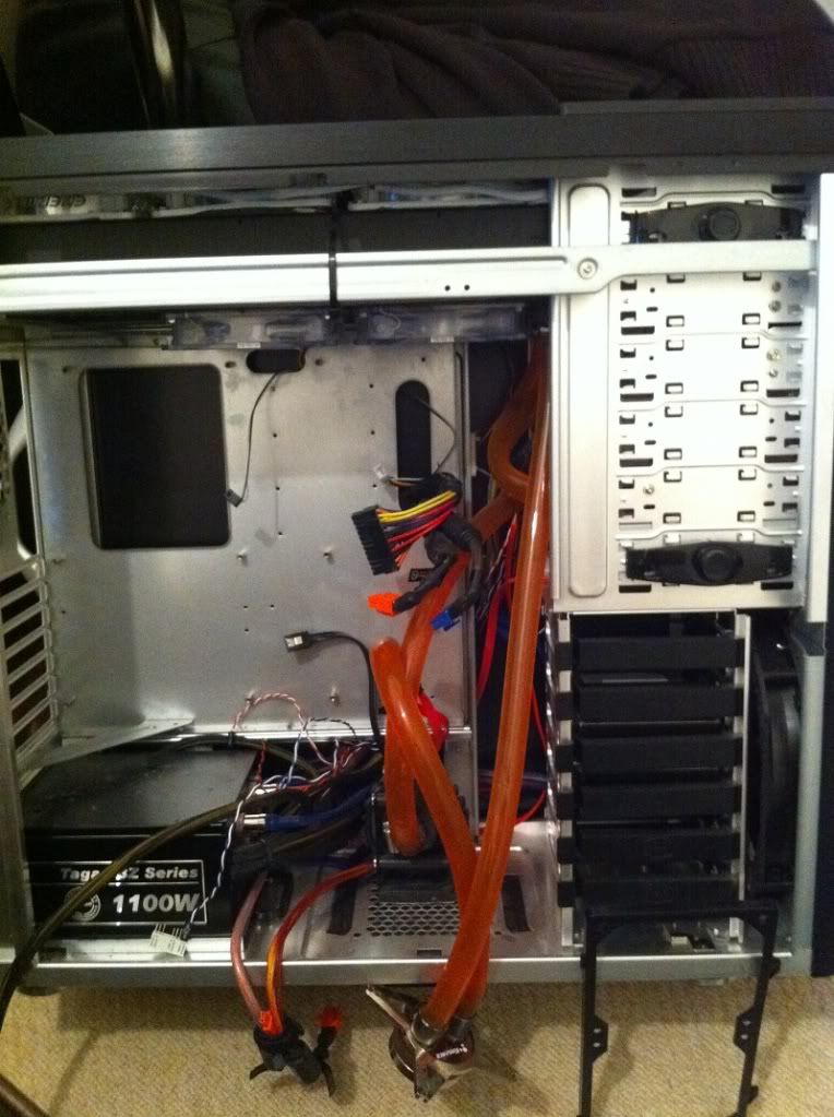
It was fun to do but quite frankly it looked untidy
Picture185.jpg


Picture183.jpg


Picture182.jpg


I then moved all of this to a ATCS 840... i know you may be asking why but i think i probably felt the need to just build something (it is all practice):cool:

115.jpg


113.jpg


Anyhow i moved house and as a result i was faced with my old U2-UFO. It stared at me with willing eyes and a soft voice saying "fill me with shiny gear!" evil evil thing!:D

123.jpg


122.jpg


121.jpg


120.jpg
 
With this project i have the following components

Asus Rampage III Extreme Intel X58
Corsair Dominator GT 6GB (3x2GB) DDR3 PC3-16000C8 2000MHz
Intel Core i7 980X
XFX ATI Radeon HD 5870 1024MB GDDR5 in X-fire
Samsung SpinPoint F1 750GB SATA-II 32MB Cache - OEM (HD753LJ) Samsung SpinPoint F1 750GB x 2
ASUS optical drive
120mm Enermax UCCL12 Cluster TWISTER Fan (white) x 15
plenty of bitspower compression fittings 7/16 fittings in black
7/16 white tubing (sorry rjkoneil this is one more build setting sail to crash on the rocks)
Tagan 1100w piperock power supply
EK-Supreme HF - Full Nickel CPU Water Block
Swiftech Laing D5 Vario
EK Multioption Reservoir X2 250 Advanced
EK D5 X-Top - Black Acetal
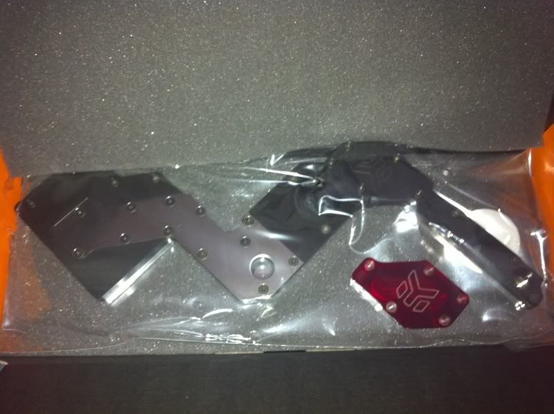
EK-FB RE3 Acetal+Nickel Block for ASUS Rampage III Extreme
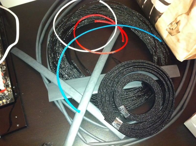
MDPC-X sleeving kit and other cable tidying goodies
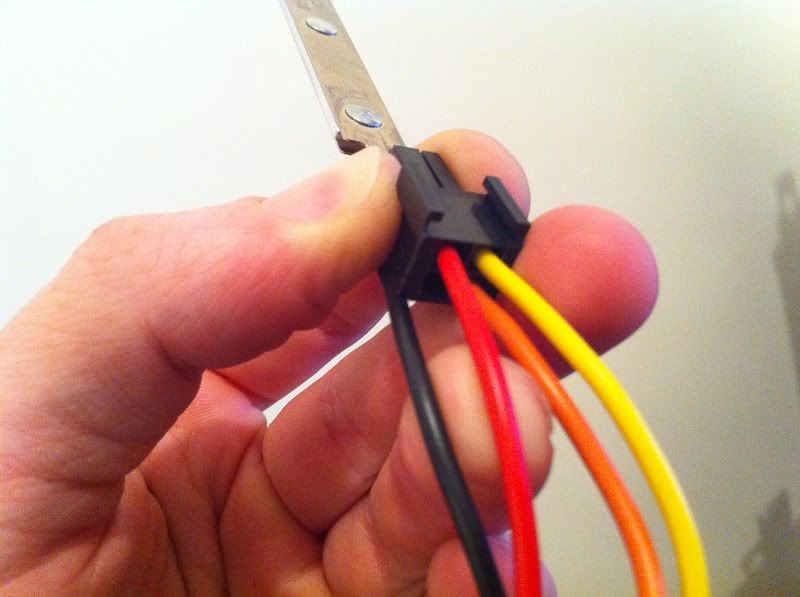
LED light strip from phenoptix (thank you for the inspiration here mrdbristol)
PA120.3
PA120.2 (thanks to Thermochill here as the sent me their very last one that was not 15mm fan spacing)
TA120.1

IMG_0323.jpg

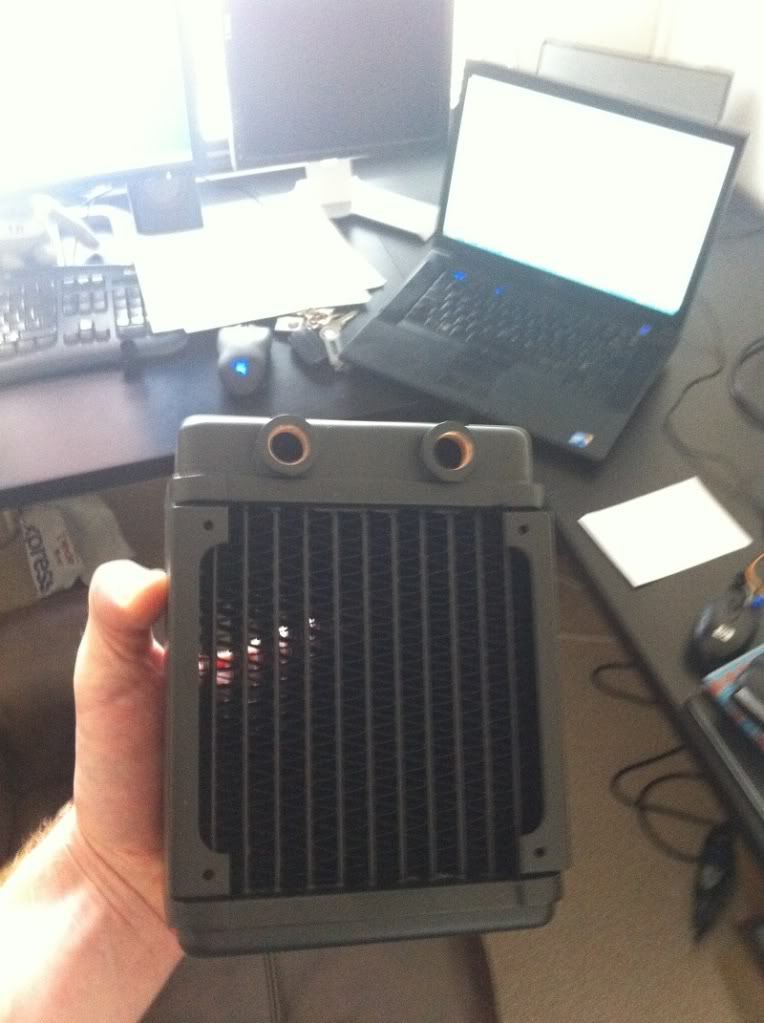
TA120.1

IMG_0314.jpg

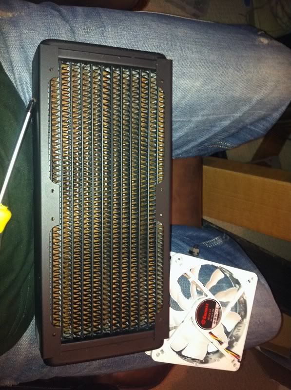
PA120.2

IMG_0306.jpg

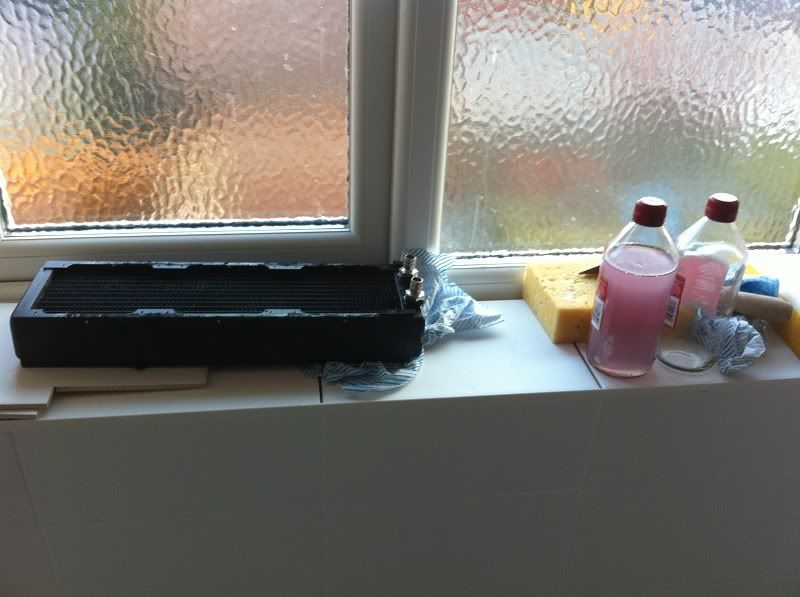
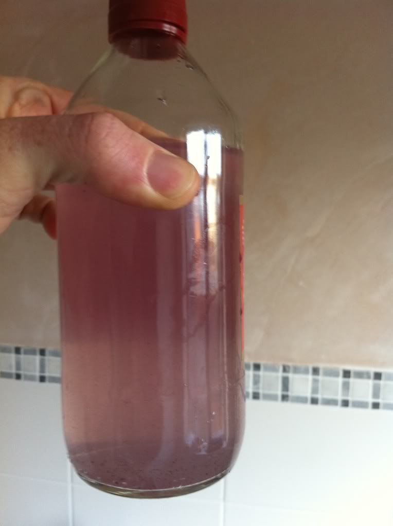
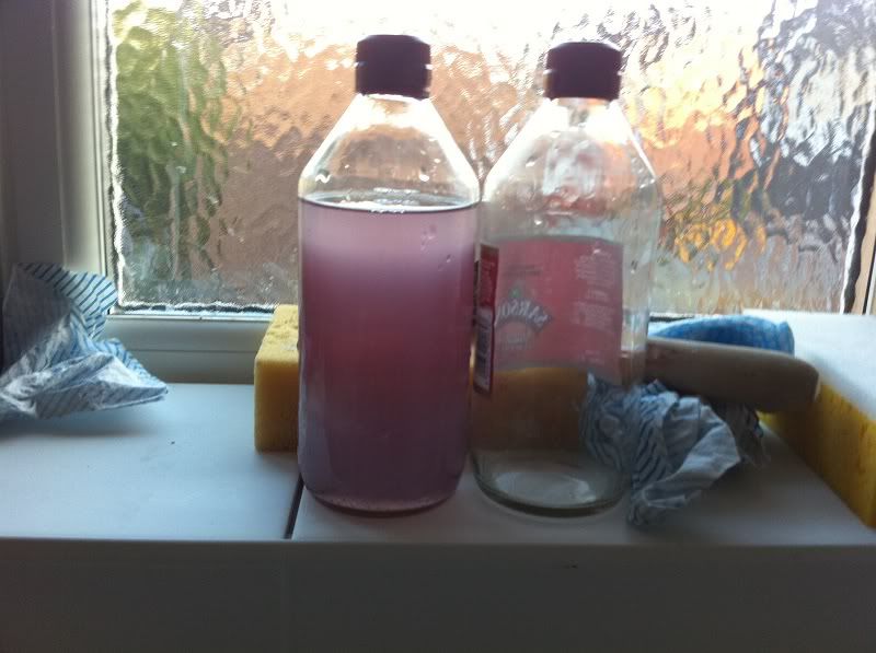
PA120.3 which was housed in all of the old builds and as you can see i am undertaking some necessary cleaning maintenance (the lovely colour is from a red dye coolant).

IMG_0305.jpg

Yuk!

IMG_0304.jpg

I followed up two white vinegar soaks with five boiling water flushes
 
Last edited:
IMG_0316.jpg

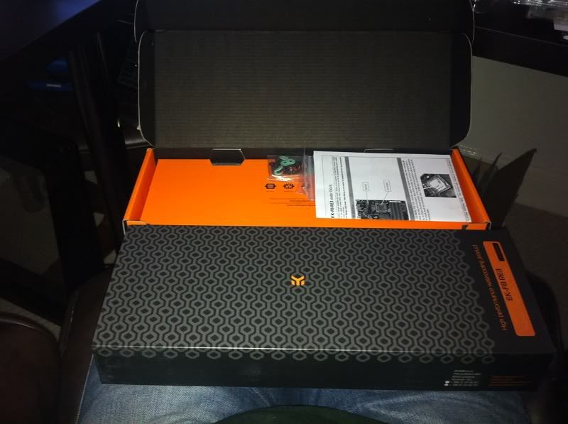
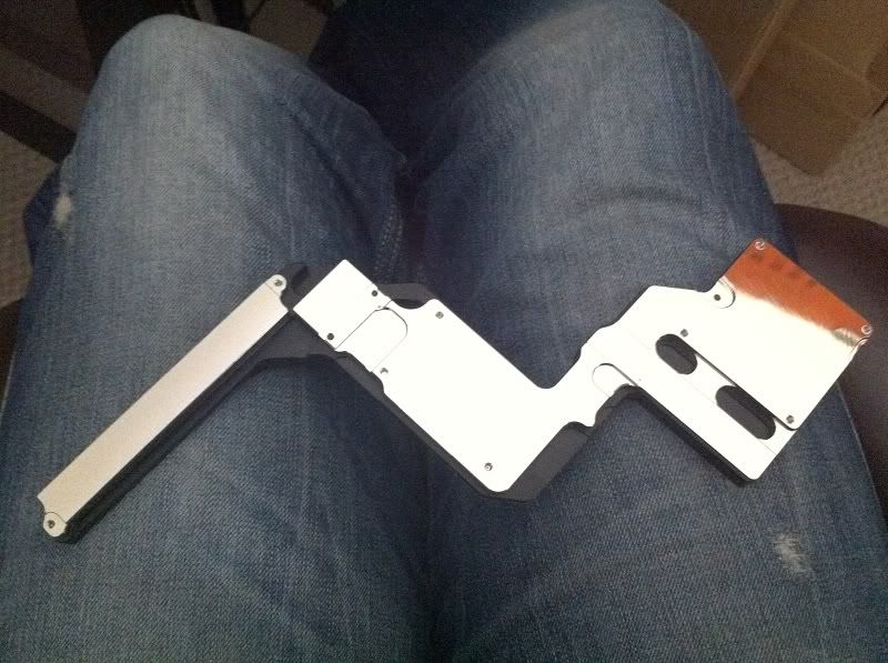
my beautiful new and shiny motherboard block

IMG_0315.jpg

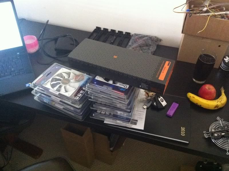
Motherboard block and fans ready to rock!

128.jpg

and the lady thought that she was getting milk tray! ha! (actually the GF did not find this amusing)

131.jpg

CPU block oooh shiny!

133.jpg

Arrrgh my eyes! ze goggles do nothing!

129.jpg

pump upgrade goodness!

127.jpg

love the res hate the mounts... a bit too flimsy for my liking compared to overall quality but i will address that at a later point
 
Last edited:
IMG_0317.jpg

I know you have all seen these before but this is my project log and i will post what i like! (please dont delete me mods :()

IMG_0318.jpg

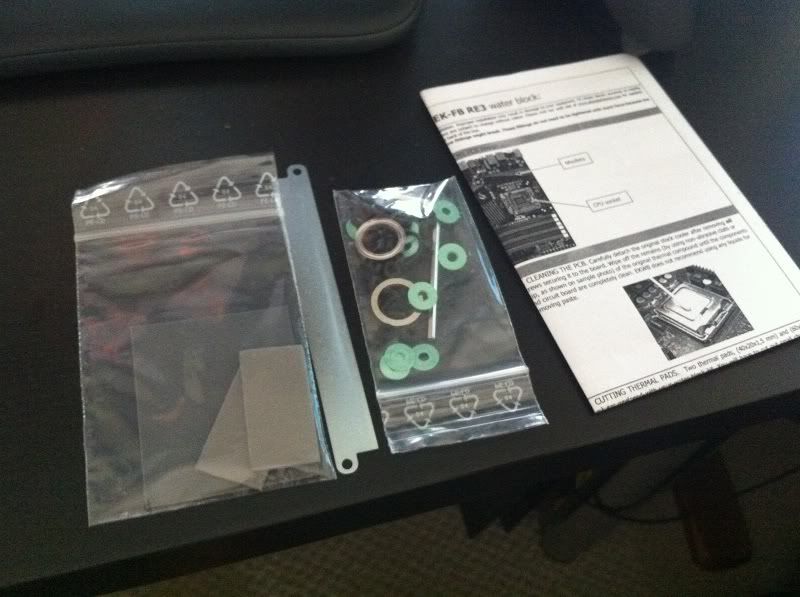
Fairly easy to use instructions and plenty of thermal compound to do the job (i used my own MX-3, TIM does what it says on the TIN)

IMG_0319.jpg

I Have ADH-Hey Look! Something Shiny!
 
Last edited:
IMG_0280-1.jpg

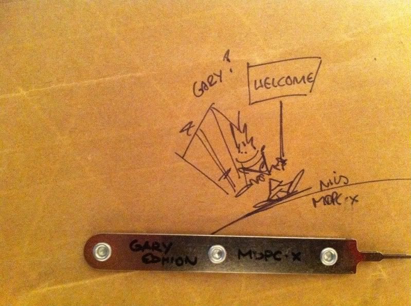
time for some sleeving... i just have to say that Nils is the nicest guy i have ever dealt with :) big thumbs up for customer service.

IMG_0282.jpg

OMG! where do i start...

IMG_0303.jpg

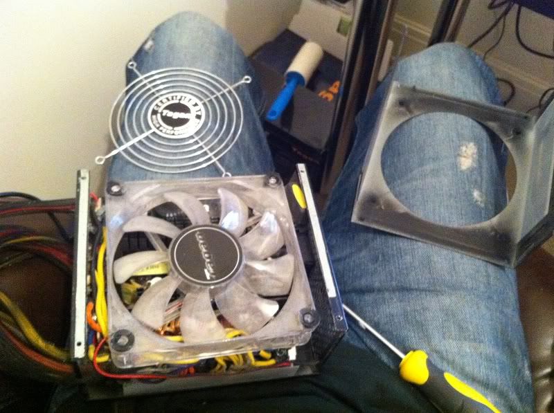
I know lets start here and dismantle the PSU...
Q. Why do PSU's hum?
A. Because they can’t remember the words
or in this case it is because i have taken it apart :D

IMG_0302.jpg

I must remember thanks to rjk who reminded me to get the removal tool!

147.jpg


148.jpg


IMG_0311.jpg


IMG_0309.jpg


IMG_0308.jpg


IMG_0310.jpg
 
Last edited:
IMG_0297.jpg

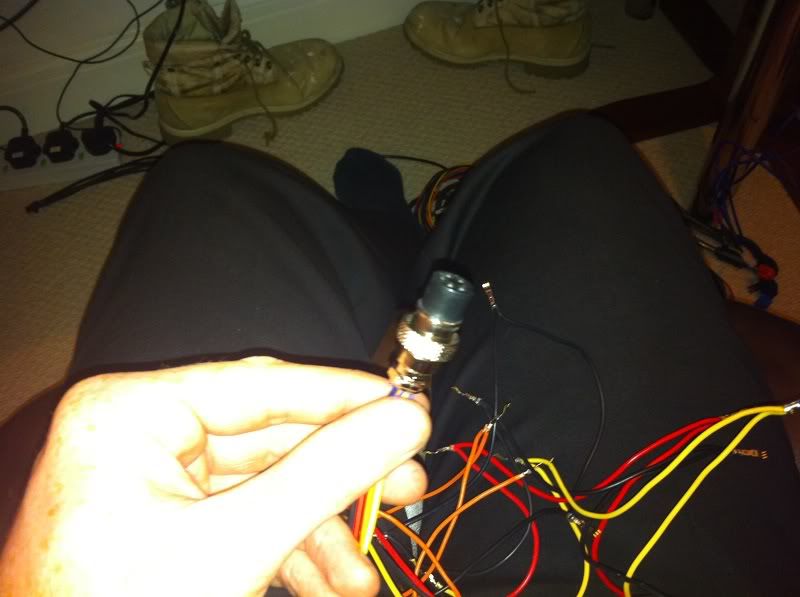
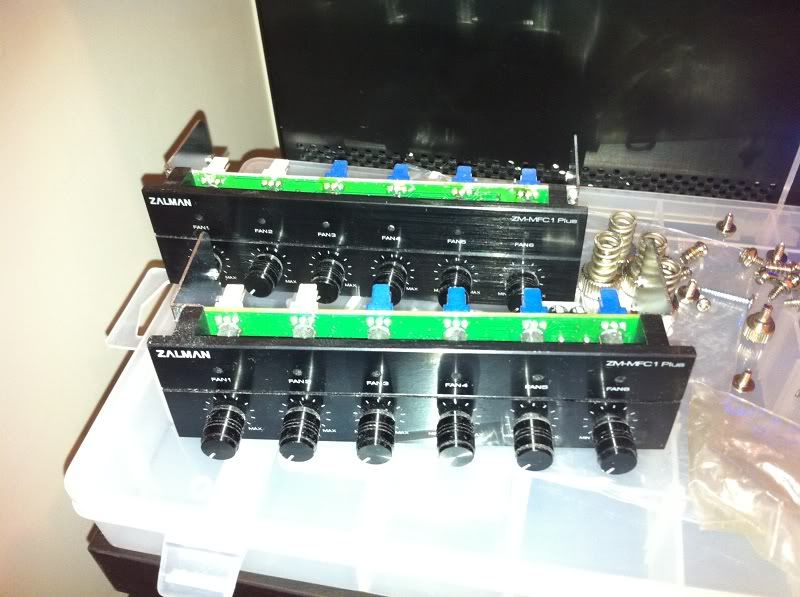
Zalman fan controllers

140.jpg

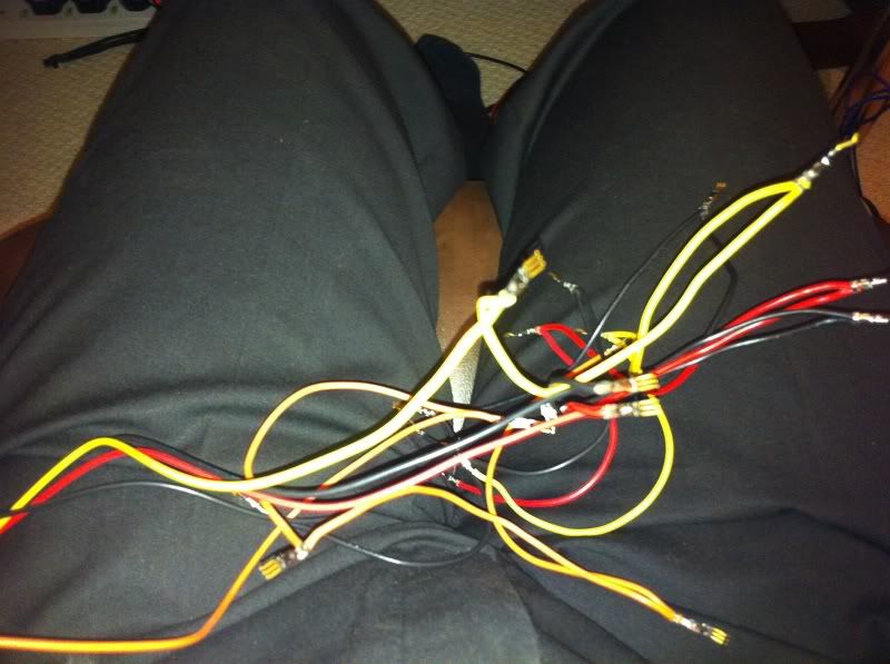
fan controllers tidied up and sleeved by moi
the camera flash is allowing the wire colours to be seen... trust me :) the cheque is in the post!
 
IMG_0301.jpg

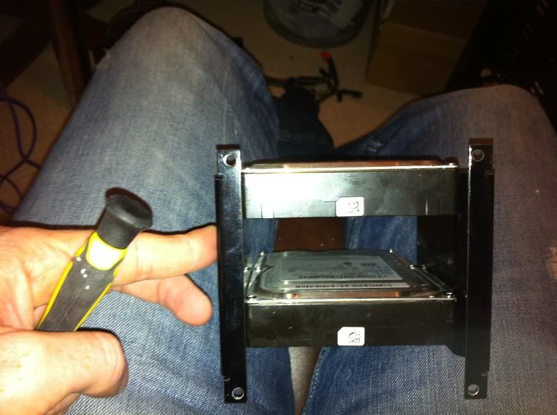
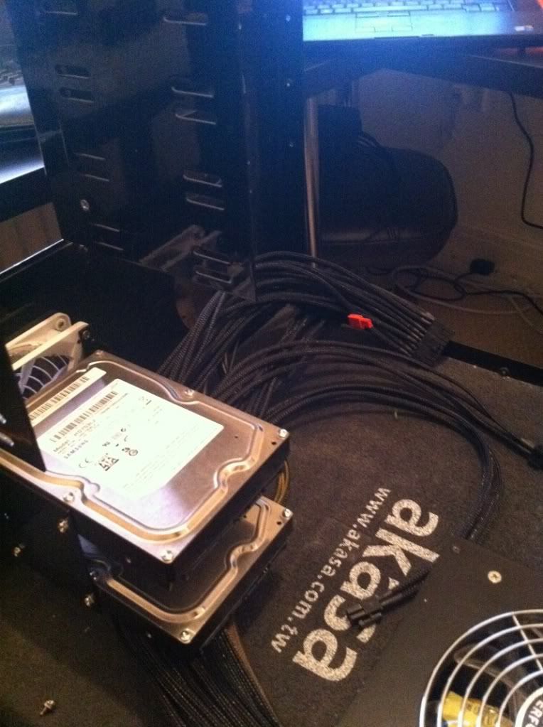
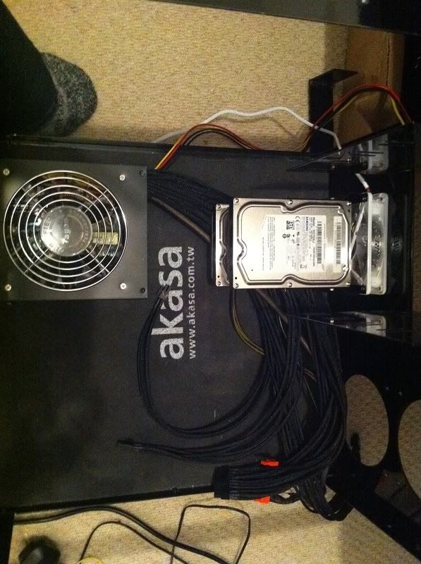
Hard drives mounted and the fan will go on the front which leads to...

IMG_0312.jpg

... one i made earlier in a blue peter style

IMG_0313.jpg

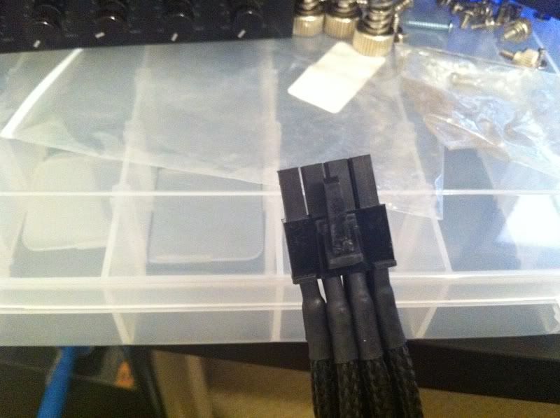
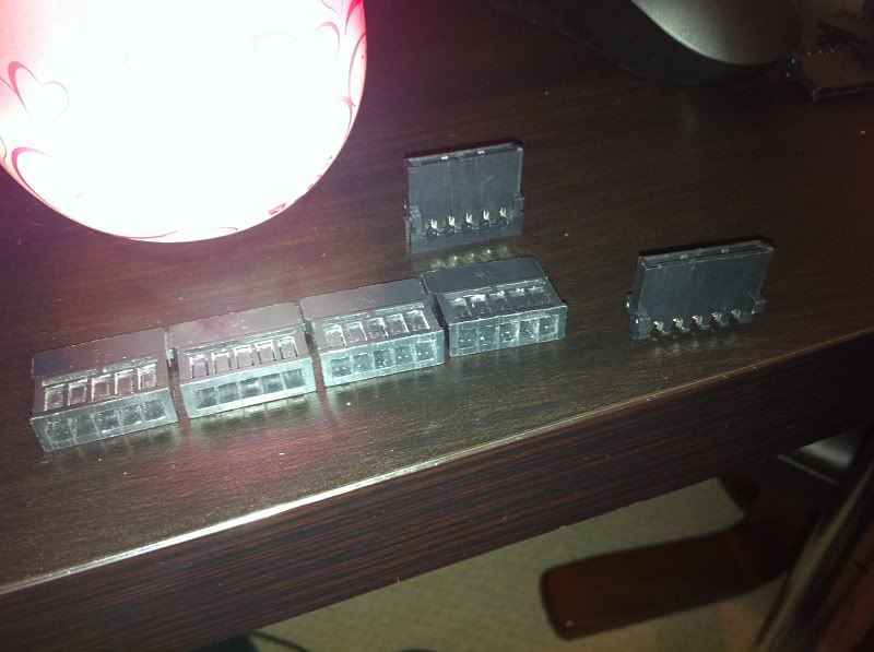
The PSU is back together (it works too!) but a tip to all who sleeve their own PSU. The sleeving drastically reduces the room you have to fit the wires back in, be prepared to fight with this when trying to put the PSU case back on unless you cable tie them together as you go.

142.jpg

this is the pump molex sleeved and tidied
 
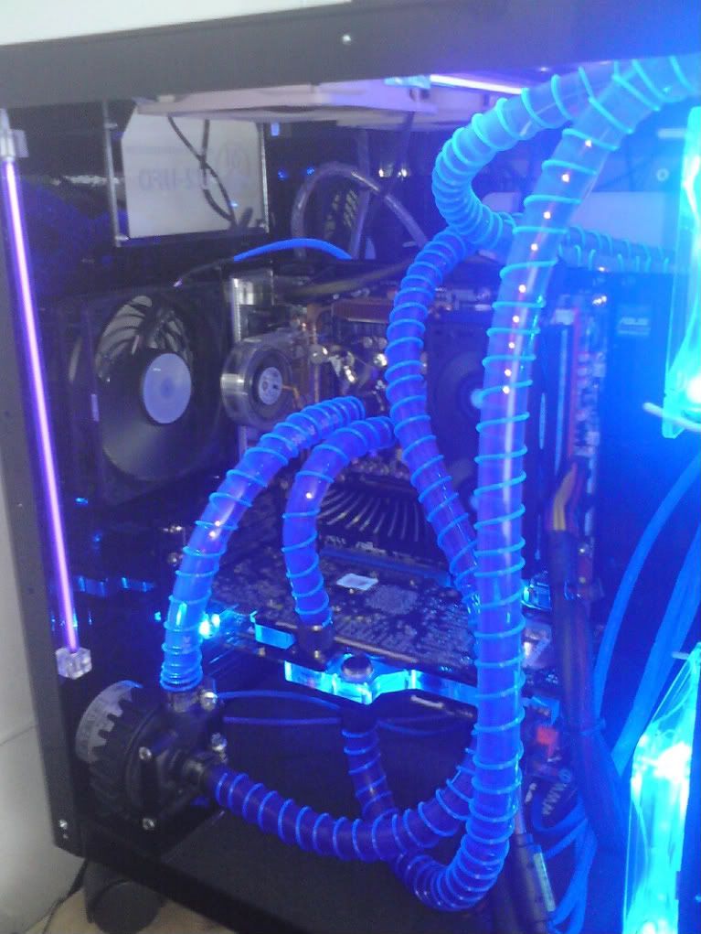
Anti-kink coils were a mistake on my behalf on the last build... i want something that looks far neater and not cheap.

The PSU took me about 2 evenings after work to do, i would put a movie on and just sit there sleeving. The hardest part is getting the pins out of the connector and rerouting the wiring because it is always so tangled.
 
Last edited:
IMG_0298.jpg

i started to add some fans to the case and give a general dust down

IMG_0276.jpg


IMG_0299-1.jpg


IMG_0277.jpg

The old case with the old motherboard ripped out

IMG_0275.jpg

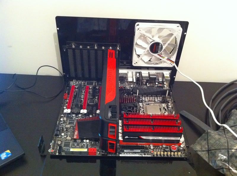
New MB goodness attached to the lovely powder coated MB tray, test fit run with the old heatsink on

IMG_0320.jpg

View number 2 :)

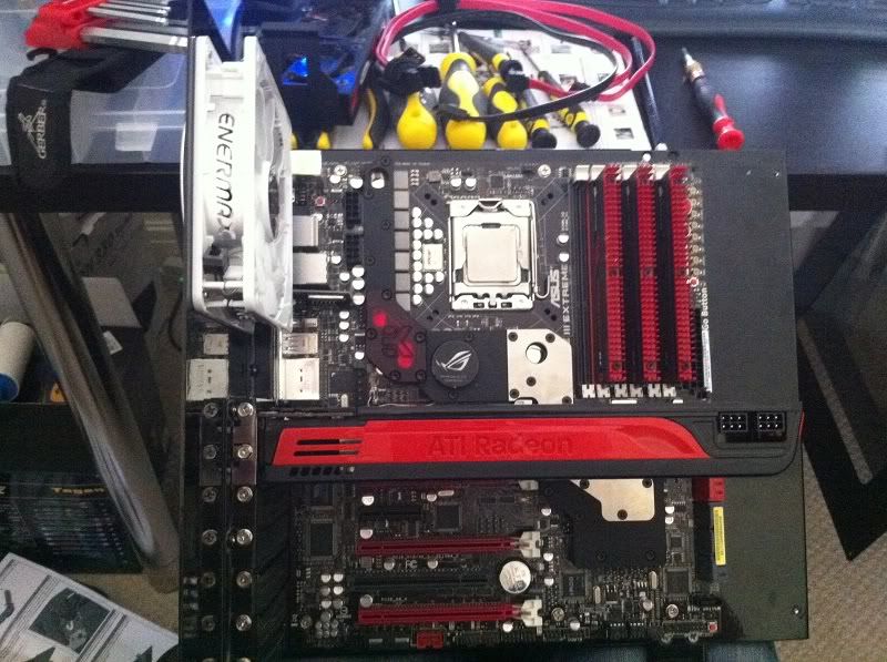
136.jpg

New motherboard with the blocks and fittings attached

137.jpg

as you can see i put the red plexi section on the board chipset with a view to putting LED lights on it.
 
Last edited:
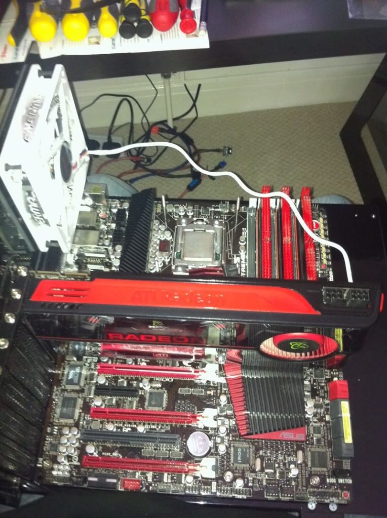
IMG_0321.jpg

I did a test fit with the card to make sure clearance over the block was good. Sounds silly but you can see how close it sits to the release catch on the PCIe. I just had to check for my own sanity
 
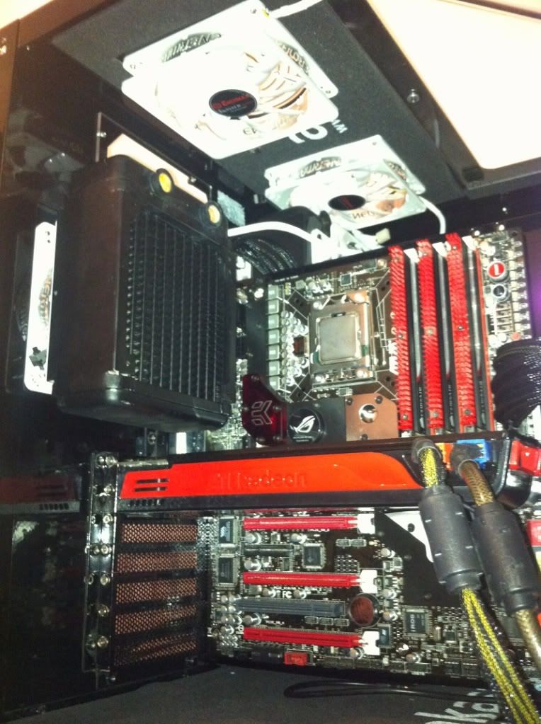
IMG_0330.jpg

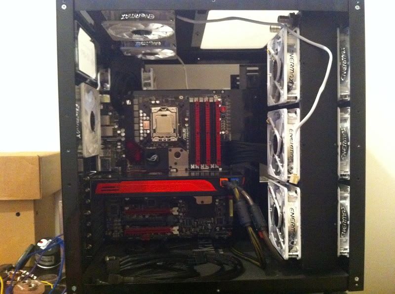
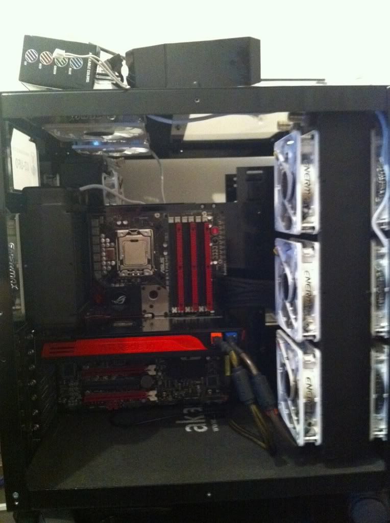
I also did a dry run with the rad mounted and the MB in place to see how my fittings would sit. I decided on a right angle bitspower fitting on the top MB connection point as it sat quite close to the TA120.1 rad.

IMG_0314.jpg

Fiddled with the PA120.2 (as you can see in the photo above it is fitted) it was important for me to source an old version because this case was designed for the old fan spacings pre 15mm rad spacings.

IMG_0322.jpg

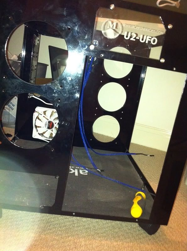
All of my braided cables on the floor of the case and pre TA120.1 fitting

IMG_0328.jpg

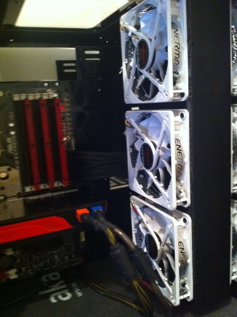
PA120.3 rad fitted with push pull fans, i will be sourcing some shrouds at some point and will add it to my lovely work journal:)
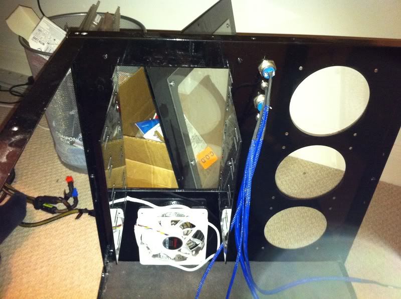
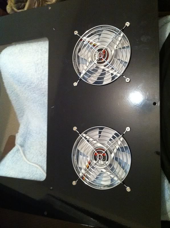
I changed the position of the top case fans so that the window sat over the MB section and the 2 fans sat at the back.
 
Last edited:
IMG_0329.jpg

I will be fitting the reservoir behind the 24 pin ATX cables and i have measured it so that i have allowed for 28cm cards with a small gap of about 10cm. I have also made sure that the bottom mount sits above the SATA connection points.

139.jpg

The otherside of the case starting to look quite messy... some serious cable tidying coming up later!
I also started to measure out the pipe run
 
Last edited:
151.jpg

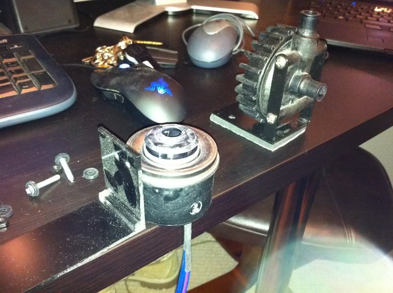
i fitted the pump by tapping some holes in the bottom of my case and using thumb screws which are the same as the case panels to attach my pump to the base. The sounds proofing also help to completely deaden the pump vibration.
 
IMG_0297.jpg

Fan controllers went in and at this point i decided to do some cable tidying on the infamous second half of my U2 case (poor options for cable tidying).

152.jpg

For the time being i have decided to cable tie all my incomng fan lines until i can come up with a creative cable tidying mod. I also ran out of connection points on my fan controllers because of the sheer amount of fans, i will be addressing this at a leater date with either another fan controller or something else (Currently looking for inspiration).

153.jpg

Side panel on and cables tidy, this section will be addressed in another month or so but first on with the main build.
 
Last edited:
IMG_0283.jpg

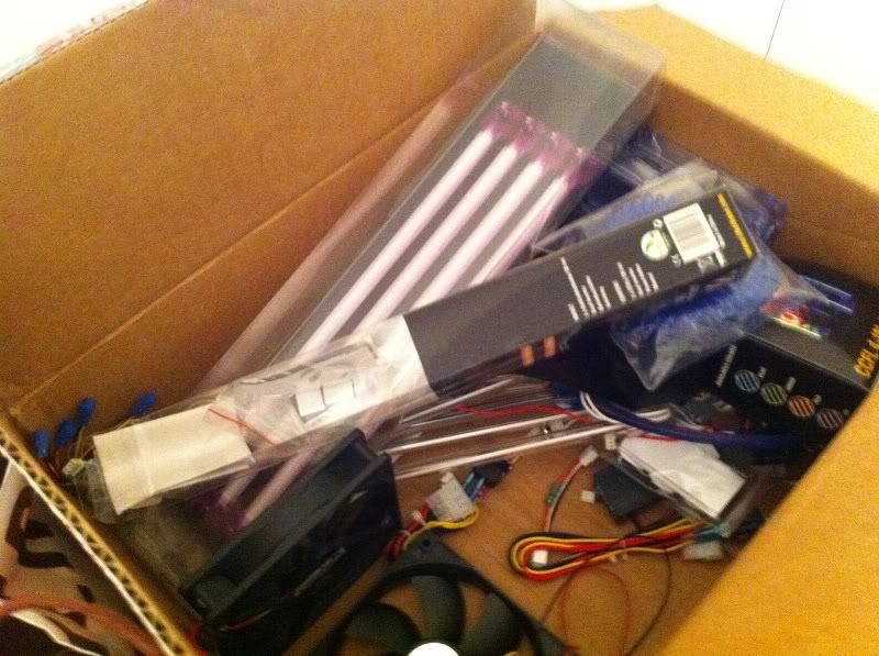
Here is my original collection of lighting and inverters etc etc. Instead of going down this route i took inspiration from mrdbristol and did my own UV LED lighting to go with the white leds (much less space and cabling taken up).

141.jpg

One easy soldering and heat wrap job later

143-Copy.jpg


143.jpg


144.jpg


146.jpg

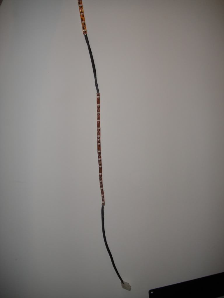
One finished 12v UV light strip :)

149.jpg

Very easily hidden and mounted... ignore the jubliee clip for the piping i ran out of 3/8 to 1/4 reducers and i am currently waiting for my back order to be filled.
 
Back
Top Bottom