PWM to Analog converter circuit

Thanks mate.

Fingers crossed.

Actually this might be a blessing in disguise. It will giv me a chance to build a dual circuit for control of higher power configurations, using 1 PWM signal and 2 B772 but possibly just the one mosfet. Interesting.
 
Nice. :)

Give me a day or so and I will knock up a super super double trouble converter for you mate. Will keep the board I made for a future build. :)

I will build it so that the two 3 pin fan headers from your cables plugs into my converter and it gets the PWM from the little 4 pin female, power will need to come by separate Molex of course. So nothing's really wasted. I will still use one switch that will hopefully set the same fan speed for both. You will get feedback from just one fan but they'll all be similar anyway.

I will show you exactly how it'll work for you when it's built. It's in my head but not so easy to explain.

Thanks.
 
So put together this piece of art this morning.

P1050281.jpg


P1050276.jpg


The black connector goes in your top GPU fan connector (as it's usually hotter), then you stick the converter out of sight somewhere, then you route the two fan connectors to your Gelid fan adaptor cables. One of the connectors is mounted on stripboard, I will do the other the same as it's much much stronger like that.

P1050283.jpg


As you may notice from the graphs below one fan does run slightly faster than the other in most instances, so I'd choose that one for your top GPU. I will mark the connectors Top and Bottom so you'll know.

Leeroy-dual-board.png


I've gone aggressive with the fan curve again because those GPUs will need their speed at the top end but if you want it slower then switch the switch down to a lower setting.

I'm quite happy with how it turned out.
 
I just thought this was mildly interesting.

How good is my circuit at keeping fan speeds constant?

Well it's pretty good actually. Measurement using Speedfan over half an hour. Variance only 5 RPM, that around 1% of the fan speed.

speed-variation.png


Compare this with my Recon fan controller which adjusted my PWM Apache's speed by 200 RPM on a setting of 600 RPM. Quite a staggering difference.
 
Last edited:
A little update anyway.

I might have already mentioned that I was looking at incorporating a trimmer/potentiometer into the circuit so I don't have to spend hours fiddling with resistors trying to get the right balance of power going into the circuit.

Well I think I've found a solution. I managed to find a potentiometer that can handle 0.5W or roughly 40mA of current at 12v.

Here it is next to another one with less than a third of the power handling. The blue potentiomter is a 5k 0.5W 25 turn potentiometer.

P1050301.jpg


Why is this important?

It is through this adjustment that I can give such good speed regulation throughout duty cycle. Without it I am stuck with whatever setting I hard wire in. A change in fans or power cannot be easily adjusted for and compromises have to be made.

There are three spots in the circuit where I can use a potentiometer to affect the power the fan uses.

1) Next to the fan itself. A potentiometer/rheostat would have to be at least 6W or more and they get very expensive, really expensive.

2) On the incoming PWM signal. I tried this and it worked up to 1 Amp but gives far too much opportunity to destroy the mosfet if someone fancies dialling it up. The mosfet got super hot. I could step it up to a large power mosfet of course but they are £1 to £2 each.

3) In the middle between the N channel mosfet and the PNP transistors. I already use resistors here so this is a logical place to start.

So this is designed to go in the middle.

So I wired a new circuit up with the transistors moved around a little and the potentiometer on the leading edge, so it could stick out the end of the heatshrink.

P1050314.jpg


P1050316.jpg


I was able to go back easily to the 5 hole wide design and now the circuit uses less resistors, has no switch and cannot be damaged by sitting in a non switched dead area of the switch location.

Here's a video. I haven't done a video for ages.


This video goes through the setup process for a few different configurations from 4 fans at 0.55A down to 1 single fan.

The circuit revision is good for fans from 0.1A to 0.55A and can be adjusted to suit individual needs. It's just a matter of dialling down the duty cycle to 20 or 30%, adjusting until the speed you want is on the fan and it's good to go. Simple. Ok maybe not as simple as a switch but it's so much easier to build.
 
Wow. I'm blown away with V2.

I know you said in the video that running one fan the potentiometer may not go low enough to run it down to 5v.

What if there were an optional adaptor similar to the 12>~7v ones that come with some fans? Obviously it'd mean the top end would be trimmed aswell but I wouldn't think that would be too significant would it ?

I might be talking nonsense tbh but it was just something that popped into my head.

Thanks to you both.

In answer to your question Resident. I don't need an adaptor at all. :D

Cast your mind back a while where I posted the following image derived from a little test I did with a bunch of different current ratings and a lower rated potentiometer and plain resistors.

ohmsvscurrent.jpg


The resistance (given by the potentiometer) to current to the fan forms a non-linear scale. At high power a slight turn of the knob results in a big change of power, yet at the low power end of the scale a slight change has a very small change in power. You may have noticed me turning the screw loads on the last couple of fan segments, whereas at the beginning it was just a couple of turns.

Instead of 5k potentiometers I just use 10k potentiometers, or 15k or whatever. I would have thought 5k would be enough but as we are dealing with non linear components nothing ever works the same between different components. So this first batch of 4 pots was just a test. I think I will probably send off for some 10k ones from Hong Kong. They'll still be fine for the 0.55A or higher uses, but the adjustments will be slighter again and possibly be 1 turn instead of 2 turns.

These potentiometers are amazing though. They give such awesome fine control. Fiddling with my older trimmers to set a voltage was tricky indeed as you try and turn the dial half a degree.
 
Well Doyll you could use a PWM converter dialled a little high so that they don't slow down all that much.

Would react something like the blue High trace in this graph.

Resident-final.jpg


With a Version 2 you could set it at say 1000 RPM at your idle duty cycle and it would speed up to 1500 by about 50 or 60 duty cycle.

I think this is the beauty of this solution. It's just so adjustable.

Other options would be to use a microcontroller to double PWM duty cycle or perhaps use an Op-amp with a low pass filter to add some gain to the PWM voltage, but unless you use an expensive precision Op-amp you lose the top end voltage.

Forgetting about PWM you could use a temperature based fan to react directly to the heat of the hard drives. I'm not sure how configureable they are and whether they just react to a predefined range of temperatures, which may not be suitable for hard drives. Again with things like thermistors and LM35 type devices it's relatively easy to get an output of temperature but not so simple to get a configureable reaction to temperature unless you use microcontrollers or a lot of discrete components.

The simpler temperature fans will use a transistor, a resistor or two, maybe a capacitor and a thermistor. All of these will be selected to suit the attached fan's specifications but wouldn't necessarily work across other fans.
 
Last edited:
Maybe one of your Phanteks adaptors would be overpowered enough to drive the fan at higher RPM at a low duty cycle. The 140mm Phanteks are actually 0.26A at 12v and the FN053 are rated 0.18A according to Akasa so should run pretty fast. For an idea of where the fan will actually power my Apache PWM which is a similar speed fan, which is rated at 0.35A actually uses just 0.11A at 12v, and 0.12v if I add some load to the blades. It might use a bit more at startup though.

It generally doesn't matter to a PWM fan if it's driven at less than 12v, although I have heard that some don't like it.


Or maybe a circuit that takes the PWM signal, checks it against a reference voltage and does the following:-

1) If lower than reference, then use it's own PWM generator to send to the fan with 50% minimum cycle.

2) If higher than reference, use CPU PWM and feed it right through to the fan.

I'm thinking something with a 555 timer and a comparator. Would be a bit of a fiddle but might be a fun project.
 
So got a new breadboard the other day and decided to have a fiddle with the circuit a bit to experiment with the gain. The original circuit has the PNP wired up in a certain way that isn't maximising the gain of the transistor so I wired up the breadboard so that I can see the difference between the two ways of wiring it up.

P1050328.jpg


Solderless breadboards are really useful for experimenting with circuits as you can easily add in components, change values and swap stuff around.

P1050340.jpg


The heatsink I've shoved on the B772 is super effective.

P1050343.jpg


With the B772 at the back it's the old circuit and with it at the front it's the experiment.

P1050345.jpg


In the video I just have a look at the differences, add and remove fans and stuff. The differences are quite suprising.

I can drive over an 1 Amp with the new configuration, albeit with a larger voltage drop of around 1.2v from 12v across all fans. The losses are just the way things are with transistor circuits. The heat generated by the PNP is undoubtedly where the voltage loss in going. At 0.1-0.4A loads the losses are less than 0.5v but when they get up to 1 Amp they go over the 1v level. This is typical of fan controllers of course, unless you have a super duper Buck converter type thing going on.


In the next video I swap out the 235 Ohm and blue 5k pot for a 1k Ohm and a 22k trimmer to experiment with the range of fans the circuit can handle with the new configuration.


With this trimmer in place the circuit can now handle 70mA to over 0.5A of fans and is more adjustable than I thought it might be using just a 270 degree trimmer.
 
Thought I'd already posted a schematic beyond that MS word one, which to be fair is very close to the end result anyway and should be close enough for anyone to work out what's going on. V2 simply has a variable resistor in series with a 300 Ohm ish resistor instead of the 10k (I think it was 10k) between drain of the BS170 and base of the B772. V1 had a switch doing the variable resistance.
 
So the other day Jay Psi asked me to make a PWm converter for his Gelid Icy Vision. I had a Version 2 set up with a 5k potentiometer so utilised that. Laying out the boards takes only minutes.

P1050423.jpg


I only had one 4 pin graphics card connector and already I'd built that onto another converter, but it hadn't been paid for so off it came and onto Jay Psi's.

P1050426.jpg


Thought I'd try out an alternate heatsink to see of it has much of an effect. The one on the left was donated by Resident and is lovely but just a tad too high, and would push the item over the magical 25mm. I decided to fit the blue one instead and see how I got on.

I wasn't too keen on the thermal pads holding the sink on the transistor when other forces are at play, such as the outer heatshrink so decided to shove a bolt through it. The trouble is then it just makes it larger so I could just have gone with the other one.

The aluminium coloured ones will be useful but will need trimming down first.

P1050432.jpg


Because I couldnt get the sink flat inside I added a blob or two of solder to aid in thermal transfer from the hotter bolt to the cooler aluminium.

P1050434.jpg


And here it is all shrunk up.

P1050436.jpg


And a shot of the potentiomter trimmer that adjusts the speed range of the fan.

P1050438.jpg


I've set this converter up on 0.45A of fans and it ranges from around 4.5v up to 11.7v, that's 550 RPM up to 1600 RPM on my 1600 fan. I don't know what the Gelid Icy Vision fans actually use though so it might be quite different in the real world.

To set the converter up to your desired speed you will need to monitor your fan speeds and this can be done with GPU-z or perhaps Speedfan.

It's easier to make adjustments when your system is idle as the lower speed is the more critical one. Clockwise will make the fans run slower and Anti-clockwise will make them speed up.

Once set up the converter can just be left to do it's thing. It should only take a minute or so to set up and then your Graphics card will control the fans for you.

Here's a shot of testing on my graphics PWM with my 3 Yate Loons. Had it there for a good hour and the sink was warm but easily comfortable to hold.

P1050445.jpg
 
Last edited:
The transistors can probably run passive at less than 0.5A load and the those little heatsinks I made out of a picture hook was perfectly adequate even when heatshrunk. I was just looking at other options. I could even make a compound heatsink out of two or three of them, and I can get dozens of them for £1.

I wonder though if I could splay out the aluminium to reduce the height a bit. I think I will need to use a bolt and nut to hold these things on as those little thermal tapes aren't really strong and would probably come off under the heatshrink.

Thanks for the link Resident. Those do look nice and are low profile. At 36p each though it's pushing the cost up a considerable amount for something that's never seen.
 
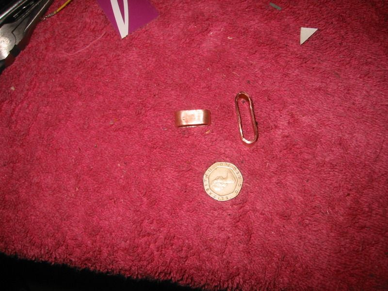
Hey that's a great idea Doyll. Copper is a better conductor than brass and is easily solderable. It would need a flatish bottom where it makes contact but apart from that it can be curved.

Want to try that. I'm wondering if I have a section of copper plumbing tubing down the shed.
 
Will have to use a ruler to determine which would be best fit, although I'm leaning towards the bigger one. There's plenty of board space, it's just the height which is the issue. Any package over 25mm thickness costs a lot more to send.
 
Just grabbed an old circuit and checked 30mm length is absolutely fine, 9mm height is ok I think and as for width 13mm will be great. Should really help with heat dissipation.

The thickness may not be much but it's probably more than the thin picture hooks.

It's always the ghetto ideas that are the best isn't it. :)

Thanks mate.
 
Thanks mate..

Guess what?

They arrived while I was at work today.

P1050446.jpg


Will slap one on over the coming days (training tonight so no time) and see what sort of effect they have, although I may have to flatten them a little more.

I should be building another one for forum member Casterina soon (for 2x SP120s) so that one will be the first to use official 'Doyll heatsinks' :)
 
Last edited:
Sounds like you went to a fair bit of effort there mate. Thanks for taking the time to do it.

Will update the thread with some piccies when I have something to show off.
 
Not a bad idea. A coin is a good mass of metal but may not solder very well so will have to check that out. I don't think coins are actually made of pure copper these days but are probably made of steel plated with copper or something. One other potential issue is the lack of a nice flat surface, although the bumps and lumps of the queens head might actually help with thermal transfer. ;)

2p might be too big for the width of the circuit but I could always use 2x1p.

Will look into it but will still use the Doyll sinks as they are really nice. :)
 
Back
Top Bottom