

Soldato
- Joined
- 6 Nov 2002
- Posts
- 9,962
- Location
- London UK
My latest little project is now complete, the Retro Wonder:-
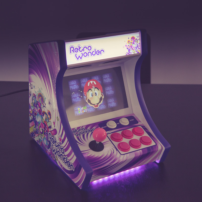
Retro Wonder 02 by Andy Baker, on Flickr
The concept
After finishing my cocktail cab (https://forums.overclockers.co.uk/showthread.php?t=18700879&highlight=startername_GSXRMovistar) I fancied building something else and as my daughter was so keen on the cocktail I thought it would be a perfect excuse to build her something. Then knowing the wife wouldn’t want another big machine in the house I decided on a bartop and taking inspiration from a couple of small builds I was impressed with I decided it would be a mini bartop.
Finished it this weekend just in time for her birthday next week.
Criteria
* Small but useable
* Artwork suitable for a 12 yr girl and not game/character specific
* Utilise a Raspberry Pi (as RetroPie had caught my interest)
* Fun!
Some pics of the finished article:-

Retro Wonder 01 by Andy Baker, on Flickr

Retro Wonder 03 by Andy Baker, on Flickr

Retro Wonder 04 by Andy Baker, on Flickr

Retro Wonder 05 by Andy Baker, on Flickr

Retro Wonder 06 by Andy Baker, on Flickr
The Build
No 3D mock up this time, due to it’s small size it would be easier to create the cab around the components.
First job was to break out an old tupperware box to test that all the components work.
* Raspberry Pi3
* 9” HDMI screen (via eBay)
* USB Zero Delay encoder
* Cheap stick and buttons
* Pair of USB powered speakers (wanted a set with a physical volume control)


Once tested it was on to the fabrication side of things, new speakers immediately stripped down.

Control panel drilled (button layout drafted in illustrator first), then glued on the front panel. I Didn’t have an appropriate sized drill bit for the smaller buttons so some careful sanding with my Dremel to enlarge the holes worked. I used 12mm MDF for this with a router to round the edges.


With the control panel and other components to use as a size reference I made some side pieces out of cardboard, once happy with shape cut one from 18mm MDF. Router used to clone the second side.

With shape decided I could then finish off the artwork, I found some public domain vector art as a starting point, modified and coloured to match my daughters room (and favourite colour purple). Added a logo and was happy with the result.

Next I cut the speaker panel, rounded the edges, and made recesses on the rear to drop the speakers into.

Top piece cut, joined, with ventilation holes drilled. As you can see from the below I’ve been using Isopod P38 for all filling, fantastic stuff.


Last piece to cut was the base plate, decided I wanted under cab lighting, yes it’s blingy but I’m sure my 12 year old daughter will like it so I routed out a recess for purple LED strips.

Slot cutter used on the sides in readiness for t-molding then test assembly to see if all the panels fit.


Connector blocks used to hold it all together and also allows me to easily disassemble/re-assemble throughout the build.

Test placement of components

For speaker grills/covering I was able to carefully remove the speaker cloth from the original USB casings and then with a little trimming and hot glue I attached them directly to the actual speakers.

Bracket for screen fitted


Then disassemble ready for paint. Nothing too fancy here just rattle cans of high build primers and then gloss white (with lots and lots of filling and sanding in-between).


Next up time to break out the wire cutters and soldering iron for the electronics. To power all the components I didn’t have space inside the cab for multiple AC adaptors and I didn’t fancy having multiple cables running to the cab from the wall sockets so decided to use one of these (https://www.amazon.co.uk/DROK-Output-Universal-Adaptor-Display/dp/B00HY3AA3S/), a small dual output PSU board that provides 5v for the Pi and speakers and 12v for the screen and lighting.

As you can see from the above the under light strips were also fitted and soldered up

A little pause/delay at this point while I waited for my artwork to be printed and delivered before I could progress. I used http://rockstarprint.co.uk who printed to laminated glossy vinyl; really impressed with the quality and finish of their work.

With the control panel covered and buttons fitted I could then continue assembly and the electronics.


Screen next to go in, fitted a small panel to the back of the screen brackets which I mounted the controller board and controls to.


Speaker panel and speakers dropped in


As you can see in the above a bezel was also fitted, this is just a sheet of 3mm clear acrylic which I masked and sprayed on the rear side to cover up the physical screen surround. Indents were made to the screen bracket earlier that allow the bezel to hold the screen down and then the control panel and speaker panels both secure the bezel down.
Quick shot from the rear showing the messy wiring. plus the revised placement of the speaker controls (upper left).

The marquee was just a piece of clear acrylic with the vinyl artwork fitted and held in place with some small plastic L shaped edging I picked up. For lighting the marquee I’m using two short runs of cool white LEDs mounted to a scrap bit of white plastic cut to size.
I was actually very pleased with how this bit turned out, when lit you can’t see the individual LEDs and the marquee has a nice uniform glow.


Onto the finishing straight, fit top panel, apply side-art, and fit t-molding.


Done!!
Well almost…one exception I have a key lock access panel for the back however I ran out of paint so that will need to be done later in the week after my daughter receives it.
Fingers crossed she likes it!
Retro Wonder 02 by Andy Baker, on Flickr
The concept
After finishing my cocktail cab (https://forums.overclockers.co.uk/showthread.php?t=18700879&highlight=startername_GSXRMovistar) I fancied building something else and as my daughter was so keen on the cocktail I thought it would be a perfect excuse to build her something. Then knowing the wife wouldn’t want another big machine in the house I decided on a bartop and taking inspiration from a couple of small builds I was impressed with I decided it would be a mini bartop.
Finished it this weekend just in time for her birthday next week.
Criteria
* Small but useable
* Artwork suitable for a 12 yr girl and not game/character specific
* Utilise a Raspberry Pi (as RetroPie had caught my interest)
* Fun!
Some pics of the finished article:-
Retro Wonder 01 by Andy Baker, on Flickr
Retro Wonder 03 by Andy Baker, on Flickr
Retro Wonder 04 by Andy Baker, on Flickr
Retro Wonder 05 by Andy Baker, on Flickr
Retro Wonder 06 by Andy Baker, on Flickr
The Build
No 3D mock up this time, due to it’s small size it would be easier to create the cab around the components.
First job was to break out an old tupperware box to test that all the components work.
* Raspberry Pi3
* 9” HDMI screen (via eBay)
* USB Zero Delay encoder
* Cheap stick and buttons
* Pair of USB powered speakers (wanted a set with a physical volume control)
Once tested it was on to the fabrication side of things, new speakers immediately stripped down.
Control panel drilled (button layout drafted in illustrator first), then glued on the front panel. I Didn’t have an appropriate sized drill bit for the smaller buttons so some careful sanding with my Dremel to enlarge the holes worked. I used 12mm MDF for this with a router to round the edges.
With the control panel and other components to use as a size reference I made some side pieces out of cardboard, once happy with shape cut one from 18mm MDF. Router used to clone the second side.
With shape decided I could then finish off the artwork, I found some public domain vector art as a starting point, modified and coloured to match my daughters room (and favourite colour purple). Added a logo and was happy with the result.
Next I cut the speaker panel, rounded the edges, and made recesses on the rear to drop the speakers into.
Top piece cut, joined, with ventilation holes drilled. As you can see from the below I’ve been using Isopod P38 for all filling, fantastic stuff.
Last piece to cut was the base plate, decided I wanted under cab lighting, yes it’s blingy but I’m sure my 12 year old daughter will like it so I routed out a recess for purple LED strips.
Slot cutter used on the sides in readiness for t-molding then test assembly to see if all the panels fit.
Connector blocks used to hold it all together and also allows me to easily disassemble/re-assemble throughout the build.
Test placement of components
For speaker grills/covering I was able to carefully remove the speaker cloth from the original USB casings and then with a little trimming and hot glue I attached them directly to the actual speakers.
Bracket for screen fitted
Then disassemble ready for paint. Nothing too fancy here just rattle cans of high build primers and then gloss white (with lots and lots of filling and sanding in-between).
Next up time to break out the wire cutters and soldering iron for the electronics. To power all the components I didn’t have space inside the cab for multiple AC adaptors and I didn’t fancy having multiple cables running to the cab from the wall sockets so decided to use one of these (https://www.amazon.co.uk/DROK-Output-Universal-Adaptor-Display/dp/B00HY3AA3S/), a small dual output PSU board that provides 5v for the Pi and speakers and 12v for the screen and lighting.
As you can see from the above the under light strips were also fitted and soldered up
A little pause/delay at this point while I waited for my artwork to be printed and delivered before I could progress. I used http://rockstarprint.co.uk who printed to laminated glossy vinyl; really impressed with the quality and finish of their work.
With the control panel covered and buttons fitted I could then continue assembly and the electronics.
Screen next to go in, fitted a small panel to the back of the screen brackets which I mounted the controller board and controls to.
Speaker panel and speakers dropped in
As you can see in the above a bezel was also fitted, this is just a sheet of 3mm clear acrylic which I masked and sprayed on the rear side to cover up the physical screen surround. Indents were made to the screen bracket earlier that allow the bezel to hold the screen down and then the control panel and speaker panels both secure the bezel down.
Quick shot from the rear showing the messy wiring. plus the revised placement of the speaker controls (upper left).
The marquee was just a piece of clear acrylic with the vinyl artwork fitted and held in place with some small plastic L shaped edging I picked up. For lighting the marquee I’m using two short runs of cool white LEDs mounted to a scrap bit of white plastic cut to size.
I was actually very pleased with how this bit turned out, when lit you can’t see the individual LEDs and the marquee has a nice uniform glow.
Onto the finishing straight, fit top panel, apply side-art, and fit t-molding.
Done!!
Well almost…one exception I have a key lock access panel for the back however I ran out of paint so that will need to be done later in the week after my daughter receives it.
Fingers crossed she likes it!
")
