

You are using an out of date browser. It may not display this or other websites correctly.
You should upgrade or use an alternative browser.
You should upgrade or use an alternative browser.
Tutorial: How to wire up a LED strip.
- Thread starter Tealc
- Start date
More options
Thread starter's postsSoldato
- Joined
- 10 Aug 2010
- Posts
- 5,508
- Location
- Somerset
Nice. I hope you don't accidentally plug a 5v USB device into that 12v powered USB connector at any stage as it won't go well.
I might be inclined to fill that light gap in the middle as you mention.
Don't worry its obviously different and labelled too.
Yeah, I may just buy a 5m strip of SMDs and find other cool places for them!
Hey Tealc, great tutorial.
Currently modding a couple of strips to go in my case, I've been testing them hooked up to my fan controller and it's worked perfectly. I've wired them up to 3pins and they plug directly in and are adjustable, only thing is since there is no yellow wire the fan controller LED doesn't light. Is there a way I can 'fake' the connection for the yellow wire so it see's the 'fan' speed as maximum (Therefor showing a red light).
Currently modding a couple of strips to go in my case, I've been testing them hooked up to my fan controller and it's worked perfectly. I've wired them up to 3pins and they plug directly in and are adjustable, only thing is since there is no yellow wire the fan controller LED doesn't light. Is there a way I can 'fake' the connection for the yellow wire so it see's the 'fan' speed as maximum (Therefor showing a red light).
Hey Tealc, great tutorial.
Currently modding a couple of strips to go in my case, I've been testing them hooked up to my fan controller and it's worked perfectly. I've wired them up to 3pins and they plug directly in and are adjustable, only thing is since there is no yellow wire the fan controller LED doesn't light. Is there a way I can 'fake' the connection for the yellow wire so it see's the 'fan' speed as maximum (Therefor showing a red light).
Thanks.
I've never really looked at what exactly the tach feedback signal looks like in any depth, beyond that it occurs twice per revolution and will either be pulled up by the fan controller to 12v or work at whatever the fan is working at.
I suspect the easiest way would be to throw 12v into the tach signal or alternately if it does need a square wave (on/off) signal then a simple 555 timer IC circuit would make it work.
Cheers for the reply chap, would putting a jumper wire between the +12v on the connector to the Tach pin work? Assuming it's not the square wave signal you speak of? If it doesn't work I won't be damaging anything?
Last edited:
You could always use a resistor as a jumper. Something like a 10k should drop any current down to just a milliamp, which won't damage anything. I doubt if it's break anything but without knowing exactly how the tach is received by circuit it's just guesswork.
You could also try feeding in the PWM signal from your motherboard. That seems to work ok.
You could also try feeding in the PWM signal from your motherboard. That seems to work ok.
Last edited:
You could always use a resistor as a jumper. Something like a 10k should drop any current down to just a milliamp, which won't damage anything. I doubt if it's break anything but without knowing exactly how the tach is received by circuit it's just guesswork.
You could also try feeding in the PWM signal from your motherboard. That seems to work ok.
Finally got around to doing this, ended up just 'jumping' the yellow taco wire from another fan connection and daisy chained it along. Working fine
")
I've just hooked up a couple of 12v strips to the bottom of the PC too, I've got another question...
As here -
Document for PCB:
http://www.frozencpu.com/images/products/pdf/lit-134.pdf
Modified 12v version from another forum (Ignore the switch wires):
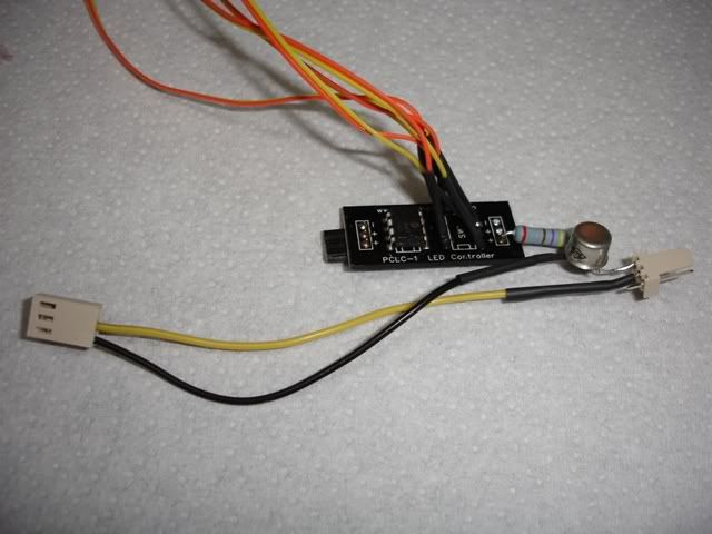
I have one of these from an older build (Without the modification) which allows you to pulsate an LED from the motherboard header. (Which is only 5v variable right?)
Can you tell just by looking exactly how he's managed to mod it to take 12v? (I.E. which resister and transistor he's using) This hopefully would allow me to make the LED's pulsate.
That looks like a 1W 470 ohm 2% resistor there, although it could be a 2W. I'm not really able to tell the wattage just by looking at them as I don't have enough experience with resistors other than 1/4W.
The transistor could be anything. Loads of transistors come in that metal package.
The motherboard header is only 5v on the 4th pin PWM output, the others are 0v, 12v and tach. I would expect that board to be 12v powered, given that it has a 470 ohm resistor, which is a good resistor value for pretty much any single LED you'd want to attach to it.
It's likely that the circuit is a 8 pin microcontroller.
That looks like a 1W 470 ohm 2% resistor there, although it could be a 2W. I'm not really able to tell the wattage just by looking at them as I don't have enough experience with resistors other than 1/4W.
The transistor could be anything. Loads of transistors come in that metal package.
The motherboard header is only 5v on the 4th pin PWM output, the others are 0v, 12v and tach. I would expect that board to be 12v powered, given that it has a 470 ohm resistor, which is a good resistor value for pretty much any single LED you'd want to attach to it.
It's likely that the circuit is a 8 pin microcontroller.
From what I can guess is it's a 555 Timer, I've given it the 12v current (555 Timer is supposed to take from 3v-15v) and it popped.
Basically what I want is this:
Don't suppose you take requests?
 I don't really have the equipment (Other than soldering iron) nor the confidence I'd get it right to do it myself.
:EDIT: Quick explanation of what I'm after - I have a 12v LED strip currently hooked up to my fan controller, which gives out 12v on a 3pin fan header. I'm looking to get those LED's to pulsate like in that video, so I need whatever circuit to take the 12v in from the fan controller and pulsate the current out to the 12v LED strip.
Last edited:
There aren't enough components visible on the board for it to be a 555 timer circuit. I suppose there could be stuff on the other side though.
Sorry I'm not really in a position to be making circuits at the moment as I'm moving house in a few days.
Sorry I'm not really in a position to be making circuits at the moment as I'm moving house in a few days.
There aren't enough components visible on the board for it to be a 555 timer circuit. I suppose there could be stuff on the other side though.
Sorry I'm not really in a position to be making circuits at the moment as I'm moving house in a few days.
Oh right, either way the controller is blown. I guess I'll give up on the idea for now, thanks for your input
Ah yes nice little controller. £4 is silly money. You couldn't even buy a microcontroller yourself and make it that cheap.
could have got it for £1.29 if I could be bothered to wait for it to come from China! I'm inpatient