[Worklog] Baby Blue - Breaking Bad themed ITX Build

Associate
Joined
1 May 2017
Posts
16
uw68fFo.jpg

Hello Overclockers UK Community and welcome to my project "Baby Blue".

Those who know and follow me already might think, "hey, i know this project" and you're right. This is my second attempt on this project since i lost my motivation and needed to start it new. The main reason for this is that i messed up a few things because i lacked experience with the tools i used. I then tried to fix all these problems but never was really happy with the results which was a bit depressing. So after a long time i decided to draw the line and begin new. I'm already pretty good with this tools right now but i will choose another way this time.


Idea:

I will keep the idea for this project. For everyone who sees this project for the first time: I want to build a "Breaking Bad" themed ITX system. The name of this build origins from the song played in the last scene of this amazing show (Badfinger - Baby Blue (Breaking Bad Soundtrack) (HQ) 1080p - YouTube). This means i'm going to use different elements from this show in my build. I want the inside of the case look like a lab using metal, a stainless steel Reservoir like the big reaction vessels in the superlab, soft tubing with crystal blue coolant and more. All in all, it will look pretty industrial. On the outside there will be symbols and stuff, things you know when you watched the show, but not made of simple decals or stickers. I want to make it look really cool.


Case:

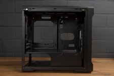
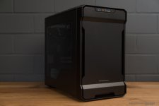
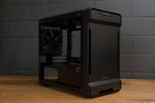
What really annoyed me on my first attempt was the case. It was the Jonsbo U2, it's a cool case but not for this mod. All the time i thought i had to fit everything inside this little case and eventually forget that this wasn't the goal for this project. Of course i don't want to use external cooling on an ITX build but the U2 was just too tiny. So i decided to get a new one and chose the Phanteks Enthoo Evolv ITX since i really enjoyed working with the ATX version. I just love the design and the features it offers.
Ury40IC.jpg

hxz5Gls.jpg

GPJetlO.jpg

For an ITX Case it's really spacious without being to big.
CJxNzAK.jpg

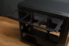
One of the features i really love, the removable radiator mount. I'm going to put the fans for the top radiator inside the top. Saw this a few times now and it seems to work.
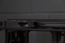
ShG9LrQ.jpg

Will be really tight but it fits. On the back i used an 140mm case fan from the ATX version. I love the simple look and it does its job.
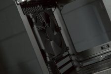
sSYdHPQ.jpg

Hardware:

The hardware i'm using isn't the newest but it is more than enough for 1080p gaming.

CPU: Intel Core i5-6600k
MB: ASUS Z170i Pro Gaming
GPU: ASUS RX480 8GB
RAM: 2x8GB G.Skill Ripjaws V
SSD: Crucial MX300 525GB M.2
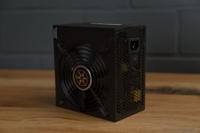
PSU: Silverstone Strider Gold 550W
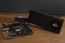
8FSQe8A.jpg

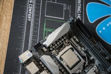
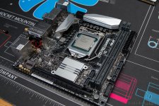
I got the board last year from ASUS and going to mod this one to fit the rest, no red allowed in here.
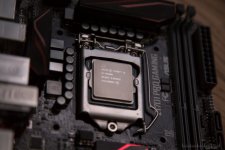
3T3acQU.jpg

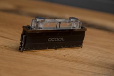
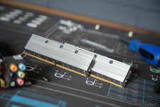
I already installed the RAM modules but i'll take these off again. The black doesn't really fit.
Gf5l1dZ.jpg

X3BM00L.jpg

Cooling:

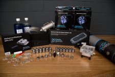
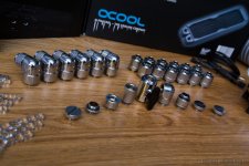
Since the whole build will be watercooled Aquatuning Germany / Alphacool sent me a big package full of stuff.
rubPdis.jpg

Unbelievable what's going inside this little build.
hdemTWx.jpg

5etjvQr.jpg

ZqMOnLj.jpg

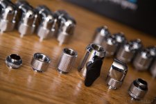
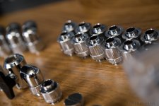
Really love the look of the Eiszapfen series, simple and shiny.

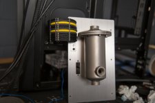
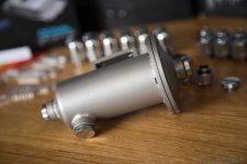
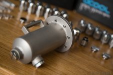
Let's head over to the reservoir. This one is from my first attempt and it was custom made. I did the drawing and went to a metalworker. It is made of stainless steel like the big reaction vessels in the superlab. To keep it waterproof i used sealing compund (i hope this is the correct word) and a flange to keep it together.
BR3HY1A.jpg

oc692a4.jpg

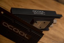
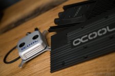
For the CPU i'll be using the Eisblock XPX and for GPU the GPX from Alphacool.
gKtjrCC.jpg

euw6fGr.jpg

gIUsvPS.jpg

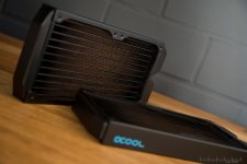
I chose 2 240mm ST30 full copper radiators, enough to keep it quiet and cool without having a fat radiator blocking the view on the rest of the inside. The fans are NB-eLoops from Alphacool, the color doesn't matter cause you won't see them later.
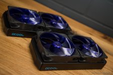
0Pl4fjR.jpg

XH9MCdD.jpg

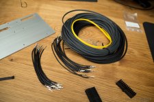
I will make the cables myself and use the new Eiskamm cable combs.
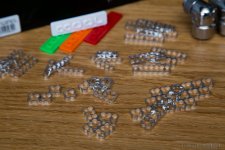
daTDHYg.jpg

CAD:

This time i don't want to mess up again so i'm using other methods, methods with which I am more familiar. Since i use CAD for my studies and know some people with a CNC milling machine, why not use this to my advantage. Some people say this has nothing to do with modding, but as long as these ideas and drawings are made by me i think it's still modding, just another kind of it. Of course i'm going to do more than just this but i had to start somewhere. I can guarantee you i have to use my dremel for this project more than once. The pieces will be milled and edged by Gosumodz.

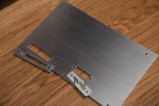
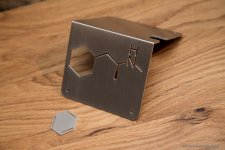
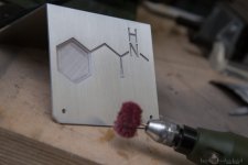
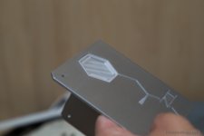
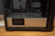
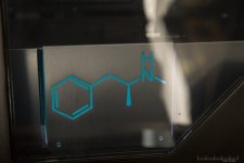
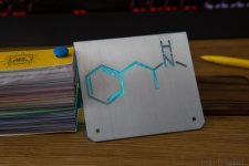
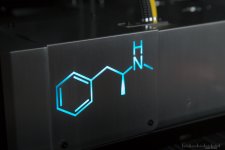
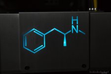
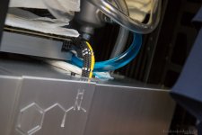
Let's stop talking and take a look at the first pieces i planned. The inside will get a new PSU Cover made of aluminium, this will not replace but only cover the original PSU Cover and will make the inside look way cleaner. The small darker piece is a standalone piece of aluminium, i made it darker for the rendering to make it more visible but i really like it this way, maybe powdercoat it black? We'll see. The chemical formula of Methamphetamine will be backlit later.
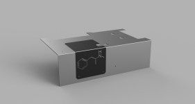
gPJGxXO.png

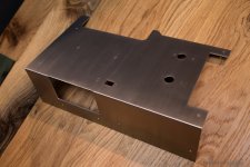
The next part is a tray for the reservoir and functions as passthrough for the 24Pin ATX und the front panel connectors. There are also a few combs for tubing and cables which will be mounted to the tray and PSU Cover.
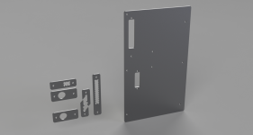
2jgAAc1.png

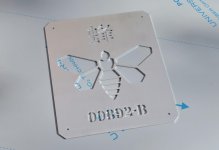
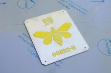
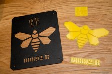
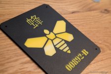
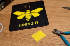
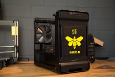
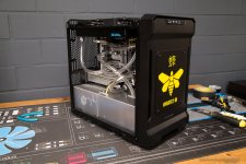
On the front of the case i want to have the "Golden Moth Chemical" Logo, the "yellow bee" that is printed on the Methylamine barrels. As i told you i won't use decals for this, so i designed an inlay consisting of a powder coated aluminium cover and yellow acrylic. This will also be backlit.
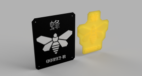
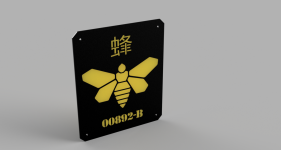
d8W7IrH.png

VzoHrdT.png

I really hope you like my idea and please let me know if you have tips or suggestions for improvement.

A big thanks to my sponsors for trusting in me and supporting this project!
 
Looking good, their ST radiators are amazing and performs just as well as their XT45mm version - worth getting a gasket for the fans, should help a little .

Surprised you didn't pick up their flow meter unit, looks like a lovely piece of kit :)

Believe the new CPU block l uses the same mounting gear as the eisbaer AIO, I think taping the backplate in place whilst fitting helps, used masking tape then removed when it was 100% running .

Thanks for the info, will keep that it mind. :)

I'm not a big fan of flow metres, they always look a bit clumsy in my opinion. Although it would add a bit to the industrial look.. I'll think about it.
 
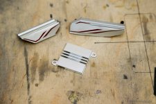
Ok guys, finally got a first update for you. My friend John from Gosumodz sent me first pictures of the CNC milled parts.
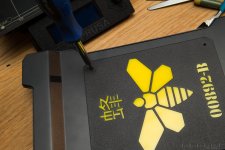
This is the front cover, i'm going to powdercoat it black once it's here.

lp4vw55.jpg

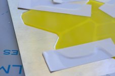
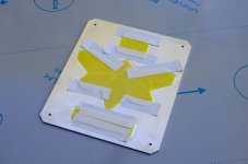
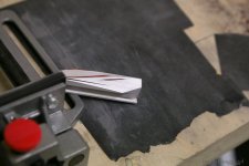
Unfortunately the acrylic plate was too thin so John came up with an idea. He milled little pockets for the inlay and divided it into 3 smaller parts.

N11bFXW.jpg

UkCDuFM.jpg

The tape is only for shipping.
And this is the front view, keep in mind that we had to leave a little gap since the powder coating will create a ~0.1mm thick layer.

O3YsU6O.jpg

3DYwz0s.jpg

Really looking forward to receive the parts and start working on the case itself. :)
 
Unfortunately the CNC milled parts didn't arrive yet because there are some problems at the post office..
In the meantime i already prepared the water cooling parts for the next step. The black finish looks cool but won't really fit the theme, so i'm going to change this.
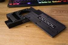
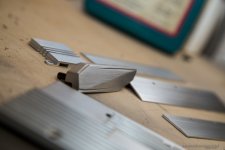
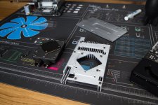
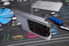
I startet taking apart the GPU block because i have to separate the aluminium parts from the rest.

dIDzKdi.jpg

by0zeGy.jpg

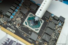
This is why alphacool blocks also watercool the rest of the card. It might not be the same as a fullcover block from other manufacturers, but it still has contact with the "water part" and not only uses passive cooling for VRM etc.

GSPmtvR.jpg

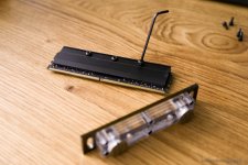
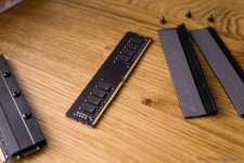
Since i already assembled the RAM modules a few months ago i'm going to take these apart aswell.

v5XOfTk.jpg

fvym3hN.jpg

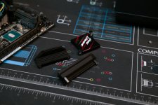
The motherboard heatsinks are also made out of alumnium.

SRmrNbX.jpg

Time to go outside :D
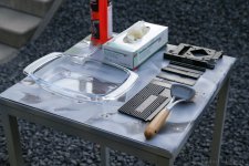
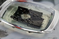
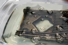
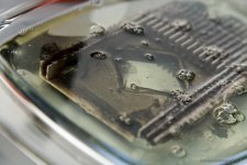
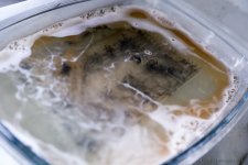
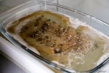
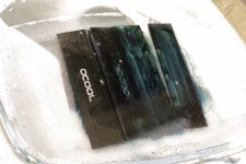
To get the black layer off the surface i'm going to put the parts in drain cleaner and leave them for a few minutes. Even though nothing will explode be sure to wear safety gloves and googles due to its high pH. Long clothes also might be a good option.

K3LChMf.jpg

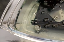
After a few seconds you can already see something happening.

9CbsGgC.jpg

iCXzYpZ.jpg

vg2d1db.jpg

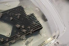
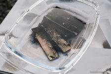
After a minute the aluminium starts to shine through, but i'll leave it a little longer.

mmLoy6N.jpg

z3KHCBx.jpg

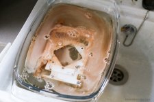
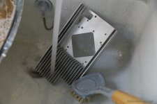
Now i took the bowl and went to the drain. When it starts to foam i take it out and wash it off with water and a brush.

R5ulHxf.jpg

ZXLZRRb.jpg

Sometimes some parts of black are still left on the piece, just put it in the drain cleaner a few minutes to make sure it's clean.
I then did the same with the backplate..

2S1ff0q.jpg

ni7cqNt.jpg

..and the RAM modules..

BajtsM7.jpg

RWCuDBM.jpg

..and of course with the MB heatsinks. The red seems to be another kind of paint, the drain cleaner had no effect on it.

XhHmaah.jpg

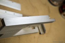
The cool thing is, the laser engraved logos are still visible after this procedure. Unfortunately some parts had these stains which only went away after sanding.
So i tried it with one of the RAM modules and it looks really great. I started sanding with 120 grit, then used some sanding fleece to create the brushed look.
Looks much better, doesn't it?

NQvw2Cc.jpg

A big thanks to my friend Matthias from Aquatuning who teached me this procedure!
 
Hi guys, just want to let you know that the CNC milled parts finally arrived. I'll be on a trip till saturday, going to update the logs as soon as i'm back.

Thank you all.

Fantastic! Aquatuning guys are great, I've spent a small fortune with them recently :(

Yes they're the best although i knew Matthias before he worked at Aquatuning :D
 
cant wait to drop in their new CPU block- frost version into a build :D How you finding their noise blocker fans ?

Can't really say since i dind't test them yet, but it hink they'll be the same as the original ones :)


I'm back and finally able to work at this mod again. No photos of the cnc milled parts yet but i continued working on the heatsinks and stuff.
Since the red didn't go away with the drain cleaner i started sanding these parts like i did with the RAM heatsink.

pgXUY0A.jpg

After 1-2 hours this is what it looks like.

Bqwoe1o.jpg

Definitely worth it.

MinpXUA.jpg

3FGaXwN.jpg

To prevent the aluminium from oxidation i sprayed a really thin layer of clear varnish on it, this way the heatsinks are still functional.

RYBwBAC.jpg

Some hours later the varnish dried and i put everything back together.

llF7K49.jpg

SFulZ1E.jpg

I decided to countersink the holes in the RAM modules, this way it looks much better.

761foUw.jpg

Qm7xoyv.jpg

Next step was the Eisblock XPX CPU Cooler.

Reg4l4t.jpg

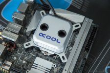
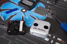
I had to swap the alphacool logo with the white one from the modding kit and i also wanted to make the cover fit better.

S7GIeS7.jpg

I took it off, started sanding it, gave it the brushed look, painted it with clear varnish and voilà.

JcV5oCk.jpg

I might paint the mounting matt black afterwards, not really sure yet.

To end this update i have some more pics of the GPU block. Next update will contain some shots of the whole hardware in the case as well as the cnc milled parts.

CBsRRro.jpg

hhcoQX4.jpg

ewTsAu2.jpg
 
Sorry for the late update guys, i was pretty busy the last weeks.

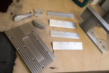
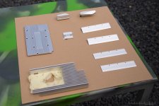
Today i want to show you the CNC milled parts from Gosumodz. I already coated them with clear varnish to prevent them from oxidation.
The front cover was powder coated in matt black with a fine texture. The few scratches are only on the clearcoat because i already installed some of the combs via screws, they won't be visible later.

YNBBVtF.jpg

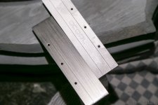
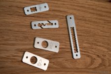
The sharp object is my own designed USB3.0 cable comb. Since you can't take off the connector i had to make a comb that closes when you mount it to the big plate.

BRkPjHb.jpg

5MGH7E9.jpg

b513jIQ.jpg

0rRnB3F.jpg

g02ZpDM.jpg

With the powder coating the inlay fits perfect!

That's not all i want to show you today. I recently got an amazing addition to my workbench.

Let me present to you:

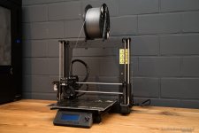
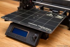
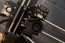
My new Prusa i3 MK2S 3D Printer!
NE2aSti.jpg

I ordered the kit version which took me 2 days to build.

T40X5LL.jpg

1yC97lT.jpg

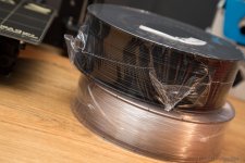
I also ordered a few spools of filament to work with, especially for this mod

KKcaJW5.jpg

Stay tuned! :)
 
love what you did to the GPX heatsink, unsure whether to follow your lead on this. would match the looks and seems it wasn't to hard from your lovely guide but might break away from the OEM feel :(

3d printer looks sweet :)

Thanks :) Go for it, it really wasn't hard and the result is amazing. Just make sure to give it at least a thin layer of clear coat (not too much though) or anodize it.
 
Good work , looking forward to seeing more of this . Do you have any plans with regards to the 3D printer for the rest of the build ?

I'm glad you asking , got a pretty big update today :)

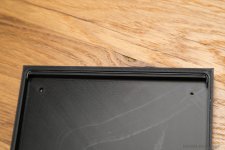
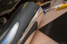
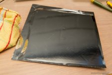
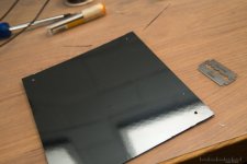
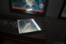
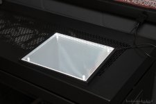
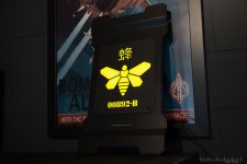
Before i start working on the inside of the case, i wanted to finish the exterior. Since the front cover and inlay are ready, let's go over to the backlighting. To create a smooth lighting i'm going to use the same concept as i used in the sLights from my previous builds. From bottom to top i'll need a frame, a backplate which reflects as much light as possible, the thick acrylic plate to break the light coming from the edges and the visible part, the inlay in this case. I use white LED stripes with a density of 120LEDs/m, these are really bright. Some people use standard clear 8 or 10mm acrylic plates and engrave a pattern to achieve a smooth light distribution. I never did it this way but i bought the so called EndLighten T from Evonik which is specially made for this purpose and distributes the incoming light from the edges very evenly. The reflecting backplate will be created with chrome/mirror wrap from Oracal, the best and cheapest way i can think of.

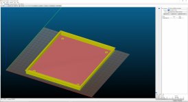
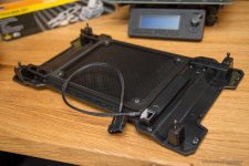
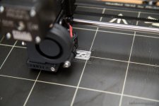
So all that's left is the frame and i'm not going to use angle profiles again - this time i want to make use of my new printer. I created a first design in CAD and this is what it looks like in Slic3r. Slic3r is an amazing tool to prepare your 3D models for printing. This is needed to set all the parameters before printing, so the printer knows what to do. Even for a beginner like me pretty easy to use!

zXrFIgN.jpg

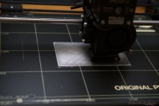
First i wanted to print this piece with PLA, one of the most common printer filaments which is recommended for beginners because chances of failing your prints are pretty low. On the downside PLA starts to lose stability at 60°C, that's why i decided to use ABS. Everything went fine, to keep the smell of molted ABS out of my room i kept the window open all the time. Right here it's printing the infill, a structure generated by Slice3r to save time and material while still maintaining the stability.

rSILpK6.jpg

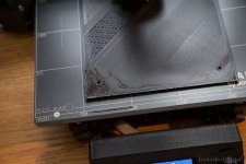
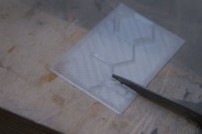
But then the open window ruined my print... 5 hours after the start it got late and cold outside, the heated bed keeps the object at around 100°C, the cold air from outside cools it down at the surface. The temperature difference leads to tension inside the object which then leads to the so called "warping".

WNhCOZx.jpg

There are some ways to correct a warped print afterwards, but in addition i also got a layer shift because i had the printer running at a too high speed. The whole print got shifted about 5mm and i aborted the print after nearly 6 hours and went to bed a bit frustrated.

The next day i decided to print it in PLA, i will try ABS with smaller prints first to get the hang of it. The LEDs will get warm, but not that warm so i won't have to worry about the PLA losing it's stability. I also redesigned the frame to save some material and time.

143vss9.jpg

YOi9SR3.jpg

Riy10r8.jpg

This time it didn't even take 3 hours and i had no problems at all, the print turned out perfect.

f9XC3wN.jpg

To secure the frame later i designed hexagonal recesses to put in M3 nuts.

JPxxeAI.jpg

Let's go over to the front part of the case, still needs some preparing.

r6VrbGd.jpg

Kt54iQ9.jpg

38xRnoT.jpg

After sanding i did a test fit.

mC0YSvt.jpg

ulDGkQb.jpg

xAcIEwP.jpg

In the meantime i printed a 1mm thick plate which will be used as the backplate later.

efq9pwu.jpg

9N4OLig.jpg

Outside i went on with the distribution plate. I bought it last year already and had other measurements back then, time to adjust this.

dv05hO6.jpg

Another test fit.

WUKbkal.jpg

After cutting the plate i needed to sand and polish the edge again.

yDwq5nA.jpg

RdN5R41.jpg

vYHV5He.jpg

This is what it looks combined.

7DiL6Y7.jpg

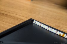
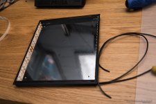
Inside again i prepared the LED stripes.

zAmIRUg.jpg

lRUhN3x.jpg

E31EiHo.jpg

The little canals i left in the frame will be used for the cables, these fit in there perfectly.

j0wOucu.jpg

zwjYrFv.jpg

Time to put the chrome wrap on the backplate..

Mu5NoqS.jpg

C47bRFc.jpg

kOWDpwY.jpg

rJYdmyS.jpg

And another test before i put everything together. You notice i test these things very often, but i rather take the time to do so than to take it apart later when something doesn't work.

gUrgwBT.jpg

With the distribution plate installed:

d4IKODA.jpg

Everything works, let's put it together.

NAFx5sZ.jpg

HAAJQwF.jpg

8GGw8IQ.jpg

And the result looks amazing!

ZjgvFk5.jpg

Last step, cable sleeving..

uHOMtdN.jpg

and done!

zEqBAeF.jpg

I really enjoy working with the printer. It's a cool gadget but when you use it for parts like this it turns into a powerfull tool and i'm looking forward to use it more often in future.
 
Awesome work! Really loving how this is turning out but I've got to ask, would it not have been easier to use an EL Panel to light the front inlay? Possibly not as bright but that is an awful lot of work to get the LED's diffused properly :D

Thanks. Yeah that might be another way and i've seen people doing this, but i never used EL Panels before and i already had all the stuff here. As long as i have the space to create it this way i will do it most of the time, you can also make it RGB, UV, whatever you want. :)
It isn't really hard to get the light diffused properly, as long as you don't have scratches or dirt inside the whole panel the Endlighten T does a great job.

wok looks epic :)

seeing how you sanded down the edges of the acrylic panel makes me wish I did the same with my Parvum case- but im to lazy lol.

3D printer looks neat- would love to 3D print myself a GPU fan shroud :D

look forward to the end build !

Thank you. Just took a look at it and that would be really sweet if those edges were polished. It's easy, just grab some sanding paper (120-3000 is what i use) and some polish, i'd recommend using a bit of water and dish soap while sanding.
 
Hi guys, got another small update. This time i also want you to help me with a decision, more at the end of this post.

Thanks guys for the kind words!

Before i start installing all the aluminium covers inside the case i had to finish the illuminated structural formula.
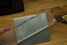
I created an Inlay in CAD using the files which were used for the CNC milling.
To make the inlay translucent i use PETG filament for this print. It will lose a bit of its clarity during the print but that's fine.

Jh7aFWh.jpg

The first layer still looks pretty clear.

cW6QpJP.jpg

But as soon as it starts printing more layers it gets more "milky".

LKBVpzn.jpg

Unfortunately the print failed as the freshly printed PETG didn't stick to the layer underneath.
I changed some printing parameters and tried til it failed again. Always a challenge to get good results with a new type of filament.

tFFZHuI.jpg

Cpw6U96.jpg

After a few tries it worked and the print got finished without problems. Still need to tweak the settings in future but for now this will do the job.

Tuv9uIB.jpg

I had to sand some edges since the inlay didn't fit properly.

y9OvonT.jpg

9rL2TaL.jpg

sxrTocL.jpg

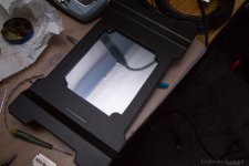
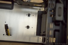
After that was done i took the new PSU cover and put it into the case to see how much space i have behind it.
I wasn't sure if i was able to build another lightbox because i only have a few mm.

PMw6J2w.jpg

P7mwMf7.jpg

I also hadn't enough Endlighten T acrylic anymore to make a rectangular lightbox. I could've cut the acrylic at an angle but that might lead to unequally illumination.

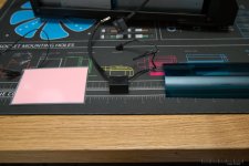
So i ordered a piece of EL foil, an inverter and some filter foil from lee filters.

bOs0MBF.jpg

After installing and testing the EL foil i noticed that it wasn't as bright as i expected .

Zglcng9.jpg

YupuUn8.jpg

Usually i would just leave it as it is, it's not that bright during the day but enough when it get's darker. I also have everything here so why not use it.
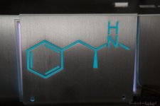
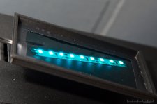
But when i was postprocessing these photos i found one that i took while searching for the right filter foil. I used my smartphone LED for the backlighting and that created a very different effect.
The inlay gets more depth and looks like it's made out of crystals.

45TktHU.jpg

What do you guys think? EL Foil for smooth backlighting or the LED variant to make it look more crystalline?
 
I'm back with a small update. Took some time since i was in vacation but now i can continue working on it.
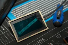
Aquatuning sent me a new Light Panel for the XPX CPU Cooler since the one i have has blue instead of white LEDs.
To make it fit better i needed the white LED so i can use the filter foil.

With the colour problem solved i wanted to create a similar effect as with the illuminated 3d printed inlay i showed you in the last update.
The plan is to reprint the exisiting inlay with PETG filament. To make this work i had to take exact measurements and create the new model in CAD.

YU2kVzD.jpg

LGn6GnU.jpg

What you see here is the support structure generated in Slic3r, after the print you remove it.

uaBrtBx.jpg

Let's see if it fits and put it back together.

RUAA5ks.jpg

ULXec0l.jpg

Definitely looks much better now.

Today i received the last parts for the custom sleeved cables. I'm going with extensions for this build since it's faster and uses less material.

eRf1b2J.jpg

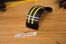
For the next update i plan to finish the cables and the backlit aluminium cover, so i can start installing everything and build the water cooling loop.
 
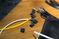
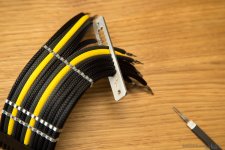
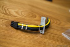
This week i worked a lot on this project and got a very big update ready. I started sleeving the cables and decided to use black, grey and yellow mdpc-x sleeve, this will give a nice contrast to the crystal blue coolant. For the yellow sleeve i chose white wire underneath, this makes the sleeve more vibrant.

awaZJm5.jpg

S1s7GHC.jpg

890ybXM.jpg

OCiFzFk.jpg

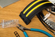
These alphacool combs work very good with mdpc-x sleeve which has some rougher meshes than other sleeves.
Before putting the other end of the cables into the male connector i need to guide all the wires through my custom combs.

jL3KSVl.jpg

This is the GPU cable.

Of7seEi.jpg

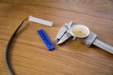
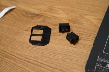
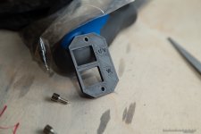
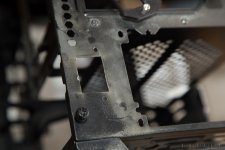
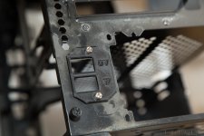
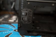
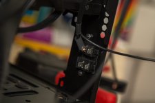
In the meantime i had a new little job for my 3D printer. I plan to install UV and white LEDs to illuminate the inside of the case later but i want to be able to turn it on and off. I ordered some little switches and printed a small cover for them. This will be attached to the back of the case.

vM1lmYW.jpg

OXHRjdH.jpg

Made a rough cutout with the dremel.

vtDRwO7.jpg

The edges still need to be sanded.

rfGYyHF.jpg

9D9KCIA.jpg

FI5TU5N.jpg

Small but very effective. I love to create such things with the printer. It only costs a few cents (with the switches) and takes less than 5 minutes to make.
Now before i install all the aluminium covers i need to prepare the pump. When designing the aluminium covers i measured everything as exactly as i could.
To get a straight axis for the in- and outlet of the pump i had to turn it a bit. There are only a few mm space between the pump and the fins of the radiator later.

0gAFaCU.jpg

Taking exact measurments is worth so much. The in and outlet are right undernath the holes.

DGkd6D4.jpg

Let's get back to the printer, which is currently printing the small lightbox for the chemical formula. Look at these clean layers.

m4lIUGh.jpg

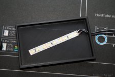
To create the "crystal effect" i will only use a piece of LED Strip without a distribution plate.

o7qsAzn.jpg

A quick test.

wUAAHmE.jpg

And we're ready to attach it with double sided tape.

hbc8MfF.jpg

I ended up putting another LED strip in there since some parts of the formula were too dark. Now i have the perfect effect that i was looking for.

9pddmrR.jpg

Turned down the exposure so you can see what it looks like. Cameras tend to make these things more white than they appear to our eyes.

RTxZpXA.jpg

2 or 3 months ago i already put some coolant into the custom reservoir to see if it gets rusty and doesn't leak any water.
Now i had to check if there are any residues inside the coolant. If so, i couldn't use this reservoir since it might destroy the pump or other parts of the loop.
But everything was fine, the coolant was clear as day one and there was no rust inside the reservoir.

wMcKPr5.jpg

5gPwdJE.jpg

I love this part of a build, especially when working with soft tubing. I really should do more soft tube builds..

daiIIMQ.jpg

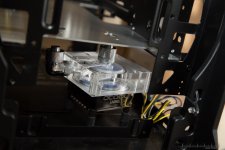
The first tricky part: connecting the pump under the aluminium cover.

rjhiXKR.jpg

3pt1y0z.jpg

It got even more tricky when i wanted to connect the reservoir with the pump.

JlSIWE5.jpg

I think it's time to put the hardware in there.

FMjwLiI.jpg

Made a fast cutout on the top radiator mount to place an inlet right above the reservoir.

GDXdxTs.jpg

oQrY2dM.jpg

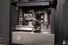
My aim for the tubing was to achieve this "chemical lab" look, tubes going everywhere and stuff like that. It's easy to put more tube in there as needed, but i had to find the balance between too much/messy and too less. And after 2 or 3 hours i think i got what i wanted.

T66ykNR.jpg

No tubes are touching each other, made use of possible short connections (CPU Block -> Top radiator) and even got some kind of looping when i connected the GPU block with the front radiator.
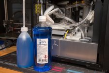
Time for some crystal blue coolant.

YEoRNgV.jpg

It looks very dark in the bottle, but it gets just the right colour inside the tubes.

SdSOXvB.jpg

3HYu7SP.jpg

Didn't want to include the loop filling in this update, but i thought i might tease you a little bit. Stay tuned!
 
Sorry for the long pause guys, i wanted to finish this project already but i had to much other stuff going on at that time. This will most likely be the last post before i can show you the final pictures since i had to do some changes. The tubing i used started to get really dirty so i had to tear down the whole loop. Turned out there was some greasy residue on the inside of the tubing. I swapped it out and got some Mayhems Clear 13/10 tubing and even after a few weeks it still looks like the first day. I also redesigned the loop since some tubes started to kink, the new one looks way cleaner and doesn't block the view on the inside anymore.

1zLPZyE.jpg

GO6ZMZ7.jpg

Next step was to add some lighting to the build. As you might remember i already installed 2 switches on the back of the case so i can turn the light on and off. To attach the LEDs i printed a little bar that can be mounted underneath the top radiator. Here you see two prints, the first one failed and is only used to demonstrate what the prints looks before sanding and spraypainting it. After some post processing you can't tell anymore if it's printed or not.

a9ZAjP9.jpg

phBxmhv.jpg

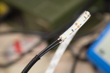
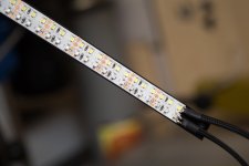
I always use these high density strips with 120 LEDs/m. One of them got white LEDs, the other one UV. So no RGB in this build :p

u38I7G6.jpg

gALXLA1.jpg

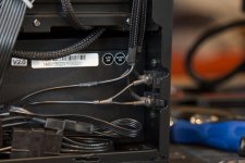
Please don't mind the cables on the bottom, it's only the back of the case :D

TUPCDxM.jpg

This one is a little blurry but i think you can see how the LED bar looks like.
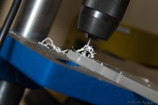
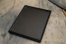
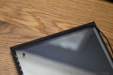
I plan to change the side panel to the new tempered glass version but i'm not going to make another update for this, since all i need to do is drill 4 holes and attach it.

4LItO3K.jpg
 
Back
Top Bottom