

In Win UK were happy to give me vectors of their logo and expressed an interest in showcasing this when it was further down the line as they couldn't work out where the 360 rad was going. Once this is a bit further along I'll give them a poke and see what they think.
You are using an out of date browser. It may not display this or other websites correctly.
You should upgrade or use an alternative browser.
You should upgrade or use an alternative browser.
(In Win 901) Asteria II: Rearmoured
- Thread starter LePhuronn
- Start date
More options
View all postsHello hello!
Given the positive response this project has received so far across the interwebs, I thought it was about time to share the first actual failure, and it's kinda big, kinda not.
The main body part of the case I'm keeping needs a few cuts to remove unneeded tabs, awkward flanges and space making for my pump. Funny really, part of the reason for designing entirely new sections of the case was to avoid chopping up irreplaceable parts, but hey ho, the needs must!
(I wonder if B Negative has thrown his 901 innards out for Celestial...)
The original hard drive area has guide runnings stamped into the roof of the case. Originally I was going to repurpose these for the PSU but they're a bit too big and will be off-centre.

DDC is getting squeezed in here behind the Titan, so we need a cutout.

Masked off...

...let surgery commence! (the next day)

The 1.5mm thick aluminium cut like butter with the hacksaw, skipped like hell with my rubbish rotary tool and took forever and a day to file cleanly. Didn't turn out too badly actually though.


So far so good...and now the fun begins. And by fun I mean annoyance, lamenting and re-thinking. Let me tell you another story...
Given the positive response this project has received so far across the interwebs, I thought it was about time to share the first actual failure, and it's kinda big, kinda not.
The main body part of the case I'm keeping needs a few cuts to remove unneeded tabs, awkward flanges and space making for my pump. Funny really, part of the reason for designing entirely new sections of the case was to avoid chopping up irreplaceable parts, but hey ho, the needs must!
(I wonder if B Negative has thrown his 901 innards out for Celestial...)
The original hard drive area has guide runnings stamped into the roof of the case. Originally I was going to repurpose these for the PSU but they're a bit too big and will be off-centre.
DDC is getting squeezed in here behind the Titan, so we need a cutout.
Masked off...
...let surgery commence! (the next day)
The 1.5mm thick aluminium cut like butter with the hacksaw, skipped like hell with my rubbish rotary tool and took forever and a day to file cleanly. Didn't turn out too badly actually though.
So far so good...and now the fun begins. And by fun I mean annoyance, lamenting and re-thinking. Let me tell you another story...
Last edited:
Sometimes you should just following your gut and then take the hints presented to you.
The plan from the outset was to use a DDC pump. I got very early measurements quite wrong and had largely committed to it for placement and loop order. After realising my folly things were still workable but going to be really tight, given the only space really I could mount the thing neatly was behind the Titan in that far corner. Overhang was the concern: I had about 50-55mm to play with, and any overhang should be no more than 2mm at worst. I could add spacers to the side panel mount to give some extra room and then edge the glass panel with some neoprene to seal the gap. Sounds like a plan.
Originally too I'd planned on using a full-cover EK block for the Titan, which meant that all top-facing ports on the DDC top would be blocked off. XSPC to the rescue it seemed as their multi-port DDC top had an an inlet on the side opposite the outlet. Perfect, I could run the loop essentially around the perimeter of the case. Trouble was, by the time I was set to go that version of the top was discontinued, and the new V2 is something crazy like 28mm tall which pushed the entire DDC assembly about 5mm too far, and that's an overhang I couldn't compensate for.
...Follow your gut, this isn't feeling viable now...
Almost packed the entire project in at that point (nothing really had been purchased) until I saw a DDC pump top on AliExpress that was 24mm in height and had in and out ports on the side. Winner winner, bought it to see how things would go. It was delivered in 3 days, except somebody somewhere messed up and nobody would admit to it: I live in Stoke, the item was delivered to somewhere in Surrey! The AliExpress seller said nothing and couldn't confirm the address he put on the parcel, I tracked the UK courier down and it was Hermes (shock horror) and, after a little social engineering, I got the customer service rep to break their operating rules and tell me what the address was. but had no reply from the person living in Surrey when I wrote them a letter asking if they'd had a weird delivery.
AliExpress refund never showed up either.
...Take the hint the universe is presenting to you...
Anyway, all ready to rage quit I see the Aquacomputer DDC top with ports on the side too, only this time they're both on the same side as well as a pair of ports on the top too. The loop order would be a bit fiddly but I could make it work so pulled the trigger. About this time too is when I found out an EK block for the Titan would be too tall to fit, so switching over to the Watercool block actually freed up some space for top-facing ports on the DDC. Winner.
And here she is: Alphacool DDC310 in Nickel with the Aquacomputer top.

And the back with my custom mount attached (temporary screws)

Mating the pump and top wasn't easy. The mounting set supplied with the pump unit were 5mm too long to attach the top and 3mm too long at the mounting side causing more dreaded overhang. Plus, the screws supplied with the top left no means to then mount the assembled pump.
...Again, take the hint...
Ultimately I decided to just include the pump mount as part of the assembly. Yeah, to remove the mount I'd have to dismantle the entire thing, but when it's in it's in so no big deal.
Test fit time!
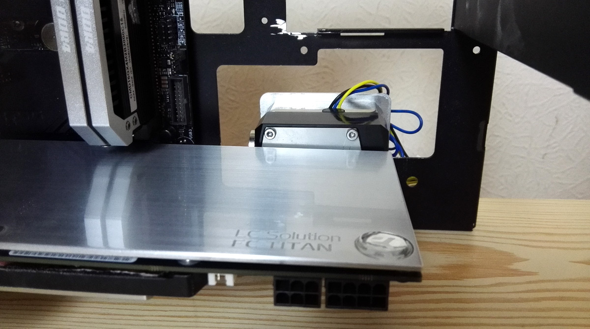

Titan is sagging a bit, I'll address that later, but all is looking good. Nicely placed, the outlet fitting doesn't interfere with any capacitors and I can even go back to a non-rotary fitting I had used originally as I have clearance.
Even my custom cover did the job

Putting a stop plug on the center inlet fouled so I made a copy without the hole.
And then I looked at the back

The fins and about 1mm of the heatsink body hangs outside the case. That's about 6mm, and there's no way I can extend the side panel mounts safely to support the weight of tempered glass. The kicker is I kinda knew this would happen but still went for it. So yeah, not at all happy right now.
So now it's a case of working out where to go now. My immediate thought is to finally take the hint and sack off the DDC and run with the Alphacool DC-LT instead. At 35mm thick I won't have any placement issues, plus the acrylic top has side-facing ports so my original loop is back in play.
The trouble now though is I have this massive space cut into the case for a pump I'm not using. The DDC is 65x65mm, the DC-LT is 50x50mm and I cut the space a bit big as well, so I have this scruffy-looking gap that looks unplanned (because it kinda is). I may be able to cover it over, we'll see.
Alternatively, do I cut off the fins on the DDC heatsink? That almost removes the overhang, and I can safely shim the side panel mounts 2mm max. I did have an active cooling idea in mind for the pump anyway so losing the fins shouldn't be an issue. Of course then really I'd need to strip the nickel off the pump housing and clean the brass up to make things presentable. In the long run it might be worth it, and some mod cred too
So yeah, a bit of a long post just to say "my pump doesn't fit and I kinda knew it wouldn't", but I do like to spin a yarn, and part of doing a public build log is to document the journey and how you arrived at your choices.
Comments and input welcome regarding this pump issue!
The plan from the outset was to use a DDC pump. I got very early measurements quite wrong and had largely committed to it for placement and loop order. After realising my folly things were still workable but going to be really tight, given the only space really I could mount the thing neatly was behind the Titan in that far corner. Overhang was the concern: I had about 50-55mm to play with, and any overhang should be no more than 2mm at worst. I could add spacers to the side panel mount to give some extra room and then edge the glass panel with some neoprene to seal the gap. Sounds like a plan.
Originally too I'd planned on using a full-cover EK block for the Titan, which meant that all top-facing ports on the DDC top would be blocked off. XSPC to the rescue it seemed as their multi-port DDC top had an an inlet on the side opposite the outlet. Perfect, I could run the loop essentially around the perimeter of the case. Trouble was, by the time I was set to go that version of the top was discontinued, and the new V2 is something crazy like 28mm tall which pushed the entire DDC assembly about 5mm too far, and that's an overhang I couldn't compensate for.
...Follow your gut, this isn't feeling viable now...
Almost packed the entire project in at that point (nothing really had been purchased) until I saw a DDC pump top on AliExpress that was 24mm in height and had in and out ports on the side. Winner winner, bought it to see how things would go. It was delivered in 3 days, except somebody somewhere messed up and nobody would admit to it: I live in Stoke, the item was delivered to somewhere in Surrey! The AliExpress seller said nothing and couldn't confirm the address he put on the parcel, I tracked the UK courier down and it was Hermes (shock horror) and, after a little social engineering, I got the customer service rep to break their operating rules and tell me what the address was. but had no reply from the person living in Surrey when I wrote them a letter asking if they'd had a weird delivery.
AliExpress refund never showed up either.
...Take the hint the universe is presenting to you...
Anyway, all ready to rage quit I see the Aquacomputer DDC top with ports on the side too, only this time they're both on the same side as well as a pair of ports on the top too. The loop order would be a bit fiddly but I could make it work so pulled the trigger. About this time too is when I found out an EK block for the Titan would be too tall to fit, so switching over to the Watercool block actually freed up some space for top-facing ports on the DDC. Winner.
And here she is: Alphacool DDC310 in Nickel with the Aquacomputer top.
And the back with my custom mount attached (temporary screws)
Mating the pump and top wasn't easy. The mounting set supplied with the pump unit were 5mm too long to attach the top and 3mm too long at the mounting side causing more dreaded overhang. Plus, the screws supplied with the top left no means to then mount the assembled pump.
...Again, take the hint...
Ultimately I decided to just include the pump mount as part of the assembly. Yeah, to remove the mount I'd have to dismantle the entire thing, but when it's in it's in so no big deal.
Test fit time!
Titan is sagging a bit, I'll address that later, but all is looking good. Nicely placed, the outlet fitting doesn't interfere with any capacitors and I can even go back to a non-rotary fitting I had used originally as I have clearance.
Even my custom cover did the job
Putting a stop plug on the center inlet fouled so I made a copy without the hole.
And then I looked at the back
The fins and about 1mm of the heatsink body hangs outside the case. That's about 6mm, and there's no way I can extend the side panel mounts safely to support the weight of tempered glass. The kicker is I kinda knew this would happen but still went for it. So yeah, not at all happy right now.
So now it's a case of working out where to go now. My immediate thought is to finally take the hint and sack off the DDC and run with the Alphacool DC-LT instead. At 35mm thick I won't have any placement issues, plus the acrylic top has side-facing ports so my original loop is back in play.
The trouble now though is I have this massive space cut into the case for a pump I'm not using. The DDC is 65x65mm, the DC-LT is 50x50mm and I cut the space a bit big as well, so I have this scruffy-looking gap that looks unplanned (because it kinda is). I may be able to cover it over, we'll see.
Alternatively, do I cut off the fins on the DDC heatsink? That almost removes the overhang, and I can safely shim the side panel mounts 2mm max. I did have an active cooling idea in mind for the pump anyway so losing the fins shouldn't be an issue. Of course then really I'd need to strip the nickel off the pump housing and clean the brass up to make things presentable. In the long run it might be worth it, and some mod cred too
So yeah, a bit of a long post just to say "my pump doesn't fit and I kinda knew it wouldn't", but I do like to spin a yarn, and part of doing a public build log is to document the journey and how you arrived at your choices.
Comments and input welcome regarding this pump issue!
Last edited:
To be honest a lot of the water components are already a year old as I had to measure up stuff before even designing the plates, so I would've missed the Aquacomputer top review. It's not an issue really, just have to make a concession on bolting the mount to the pump as part of the assembly.
The overhang image is a bit misleading; ignore the big sticky-out bits for the actual screw as they're the only M4 screws I have long enough to assemble the pump with the mount. It's the heatsink fins that are the issue - look just above the grey grommet and you'll see the fins stick out the same distance, so that's 4mm too far and the glass panel wouldn't even touch its screw holes.
Now, since this was bugging me last night I had another check. The total pump + top assembly is 45mm including the fins, and I never would've committed to the DDC after fixing my stupid measurements the first time if it was any more than that: I have 45mm from the back of the GPU to the outside of the case, so give or take 1mm I would've made it work. It might be because that part of the case is wonky without being bolted to anything but the pump does actually fit a lot better than those pictures suggest on a second attempt without the mounting in the way (it was contributing to the overhang).
So, I'm going to trim down the pump mount to get a tighter fit and try again once the case parts have been trued up and test-screwed together. Then we shall see. I'm not adverse to sanding the fins down a bit either (it was part of my thought process way back anyway), but removing them totally will be a ballache.
Knowing what a DDC is like for cooking itself, I have planned an active cooling solution as part of the assembly - underneath the pump in the fan assembly area will be a slim laptop blower turned down real low to gently waft air over the heatsink. Originally the plan was to do it over the fins, but it may just be onto the heatsink body now. Every little helps.
So yeah, the DDC (once again) may be viable.
...please, please, take the hints the universe is throwing at you...
Bent as a nine bob note!

Between awkward bends, multiple re-bending of bits, cutting, trimming and generally handling the piece, there literally wasn't a right angle anywhere on the main body panel.
Hopefully with guide jigs made (I won't rant about how my brand new circular saw was off by 3 degrees and my MDF stock had warped), bolted to the main radiator and everything clamped and screwed together this bloody thing will remember what shape it's supposed to be before I start drilling NEW holes rather than just matching existing ones. Need to break out the JB Weld too to fill in a couple of incorrect holes and re-drill.
But, once I can get this main bit finalised and back into the exterior skin I can then test fit the full case and components, and then the floodgates will open with lots of more interesting stuff!
Last edited:
Whether it stays put or not is a nice-to-have rather than a necessity now given I can crowbar the bugger into shape with these various jigs and bits. I have some filling to do to reset some holes as I said, but at least I know the shape I need is doable with some "gentle" coaxing. It'll all slip again when I sand everything down to remove the stretch marks on the bends, fill some ugly gouges and fix the horrible dent where I found the only soft spot on my bathroom floor when I marked a drill hole with a punch!
Plus no doubt it'll slip again when hung up for powder coating a bit later on. But fingers-crossed tomorrow I can mark out the additional drill holes, straighten up the other case parts and test fit everything together.
It's been annoying me but I'm still excited!
Plus no doubt it'll slip again when hung up for powder coating a bit later on. But fingers-crossed tomorrow I can mark out the additional drill holes, straighten up the other case parts and test fit everything together.
It's been annoying me but I'm still excited!
Sounds like you're one step closer to losing your last marble
It's coming along nicely!!
Any chance you could walk us through (pics or even a vid would be nice!) how you did the sheet metal bending please?
Many thanks! It's been a bit scary and frustrating given all of my backup pieces were trashed, and still needed some bodging to get things working, but overall I'm pleased. Core body work almost done.
As far as a walkthrough for the folding goes, there's not really much to say. I have a sheet metal folder: https://www.stakesys.co.uk/sheet-metal-folders/sheet-metal-folders/sf460x1-sheet-metal-folder which replaced the MDF version I made due to inaccuracy (although still great for acrylic), and some vice jaws: https://www.stakesys.co.uk/sheet-metal-folders/sheet-metal-folders/vice-mounted-folder
The folding itself is simply just putting your material into the folder and line up your bending edge as required, clamp the chunky brace on top to prevent everything moving and then pull up the handles to make the fold. The folder is narrow enough you can make close bends on each side of the material (not quite box folds but close). The smaller tabs and fiddly bits were done in the vice clamp; put the jaws into the open vice, line up your material and tighten the vice just like a V-press.
I would heartily recommend the sheet folder. It's a simple device, nice and accurate and conceptually a breeze to use. The tricky part comes down to the material itself. You need to know what the bend radius of your material is going to so you can design your pieces accordingly, and also where to position them in the folder. A lot of my wastage came from incorrect bend radius measurements and then knowing where the actual bend will occur using the folder. Once you're good with that then it's all golden.
As far as the vice jaws go, I think I wasted my money if I'm honest because even if you get the wide one, you can only fold something that's no longer than the depth of the vice itself. For example, those awkward tabs you can see on the main body were longer than the depth of the vice, so it was bottoming out before I could even line the thing up. The deeper the vice, the more you can fit in. Ultimately I bodged it by clamping 2 lengths of iron angle to my workbench, putting the jaws on that and then slowly closing up the workbench. Did the job, but it's awkward.
So metal folder yes, vice jaws perhaps.
The reservoir mount has been redesigned actually, but I've always been planning something unobtrusive. Not sure if a friend has been able to wangle some laser cutting time for it so I'll have to cut it by hand, which will be a pain given it's mostly circular with very precise mounting holes in it!
Thickness = radius is a good rule of thumb, but I've found that resistance also contributes. I've found if you have a lot of material along a fold then the radius will increase, conversely the radius will decrease if you're not bending much. For example, I'm using 1.5mm thick alu and the main body panels are about 160mm at their widest. I ended up with a bend radius a touch over 2mm along those bits. The tabs and such which are about 20mm or so wide actually folded much tighter at 0.5-1mm radius. Also the gauge of material you're folding has an effect too. I'm using 1050 gauge alu, but you can get more expensive stuff that has negligible radius.
You can also cut a channel along the fold line to bend tighter too, which is really useful if you're doing thicker sheets and still want tight bends.
As far as the scratches go, I've had more marks from the bender than the vice jaws. The bending brace is about 5mm thick, but has 45 degree edges on it to allow for over 90 degree bends (which you want to prevent springback). This means the folding edge is like a knife and cuts into the surface, so will require sanding down and cleaning up. I'm also scraping very thin layers of JB Weld into the deeper marks to act as a filler. Ultimately I'm powder coating so marks like that won't be an issue, but if you're going for a raw metal look or painting then you'll probably need extensive surface cleanup afterwards. Wet sand with 400 grit, 800 grit then maybe 1200 grit will smooth everything out.
I think my powder coating is going to be quite cheap. Local place reckons they can do all of my bits for about £40, maybe less. But to be honest, if you're painting properly then you're supposed to be sanding down the metal, multiple thin coats of primer, sanding the primer, multiple thin coats of paint, sand the paint, thin coat of protective.
Honestly, by the time you've done all that you would've filled in any surface imperfections with the primer so it probably sounds more daunting than it actually is. The worst marks I have you can feel with the tip of your fingernail, but you can't feel them with your actual fingertip. Then I sanded a few down to see and it's a non-issue. They are visible on the metal, but you can't feel it. Like I said, it's only really an issue if you plan on keeping a bare metal look, and even then you can buff it all out.
Don't be deterred.
Also, aluminium is a very soft metal and I've had my g-clamps leave rings in the surface where I've tightened up a lot. Steel won't mark anywhere near as badly, if at all.

I have a BIG update for you. Not so much in volume, but in significance. After 2 years of planning, design, redesign, stress and very scary moments I think I might actually have the case...

And for all those who asked the question directly, here is the big reveal: the Alphacool UT60 360 radiator mounted inside.

Close-up of the rad in situ

And after all the trouble with bending the lower L incorrectly, trashing all backup pieces, bend radii throwing measurements off and ultimately taking a hacksaw to lovely laser cut work...

It's turned out pretty much bang on. Hell, I might have even taken a tiny bit too much out!
Things still need a bit of adjustment to straighten bits up, but here's a cheeky shot of the back with a vanity plate I put in to cover the PSU opening. Should look nice once cleaned up and brushed to replicate the case exterior.

And to wrap up, I simply had to throw the hardware into the case. Consider this a teaser and a spoiler for when everything comes together


Forgive the grotty photos because I'm over-excited and over-tired! Still lots to do to get the case cleaned up and finalised, but I think finally I've now broken the back of it. The grunt work is done, so everything now is a million little things so I can potter about and do bits here and there, rather than have to schedule in large blocks of time.
Plenty more to do, plenty more to see, and plenty of things I've not even talked about yet

Stay tuned.
Last edited:
Things have gotten busy at home so I don't have anything of note to share on the build, but I've just found out this project has been nominated for bit-tech's monthly modding update.
That is scary and huge news for me. Even got a vote too, which is mindblowing considering the amazing quality of the other nominees
That is scary and huge news for me. Even got a vote too, which is mindblowing considering the amazing quality of the other nominees
Cheers Frank, all the positive support is very much appreciated. Ideally I want to finish off some fiddly bits with the blanking plates on the lower half, but it's annoying me so I might leave it for a bit
With the PSU moving to where the hard drives originally sat, and no M.2 socket on the motherboard, you might be wondering "where will storage go now then?". That's the bit I want to show next, but I need to pull the trigger on LED strips and acrylic first")
With the PSU moving to where the hard drives originally sat, and no M.2 socket on the motherboard, you might be wondering "where will storage go now then?". That's the bit I want to show next, but I need to pull the trigger on LED strips and acrylic first
Greetings!
Not much to say at the minute as I'm trying to get some money together for the next phase of the project. Rather than let this log vanish into the ether, I thought I'd share a little preview of something upcoming. Very rough photos as this update has been thrown together rather hastily
With the radiator occupying the entire lower chamber of the case, and the PSU residing where the hard drives would usually sit, I need to relocate the storage. Since I'm sticking with 2.5" drives right now, I thought I'd make the new drive position a bit of a feature. So, one drive mounting plate drawn up and cut:

and will be placed on the back of the case over the motherboard cutout, something like this

Space for 2 drives; I'll be repurposing my existing Samsung 840 500GB as it's still in excellent health and pairing it with one of those slim 7mm tall laptop drives for file storage, more than likely the Western Digital WD10SPCX 1TB. Allow this battered Seagate to illustrate.

I'm going for a wireless look for this storage plate, so each drive has a cutout for running cables out of the way. I'll be using those ultra slim Silverstone CP11 SATA cables to tuck under the GPU, route under the motherboard and out the big case cutout into the storage plate. For power I'm going to try and make up a veroboard for sharing the power a few ways as I have something fancy planned (and is what's costing the money)
Given the visual mismatch of a mechanical dive paired with SSD, I'm not leaving the drives exposed. Pair of aluminium covers will be used, and I've cut the Asteria II and In Win branding into them for some visual flourish paired with something to come later.

It'll be along these lines when they're in position:

That's the general gist of it anyway")
Hopefully I can scrounge some money together soon and get the acrylic and LED strips in and get this bit put together properly.
Catch you soon!
Not much to say at the minute as I'm trying to get some money together for the next phase of the project. Rather than let this log vanish into the ether, I thought I'd share a little preview of something upcoming. Very rough photos as this update has been thrown together rather hastily
With the radiator occupying the entire lower chamber of the case, and the PSU residing where the hard drives would usually sit, I need to relocate the storage. Since I'm sticking with 2.5" drives right now, I thought I'd make the new drive position a bit of a feature. So, one drive mounting plate drawn up and cut:
and will be placed on the back of the case over the motherboard cutout, something like this
Space for 2 drives; I'll be repurposing my existing Samsung 840 500GB as it's still in excellent health and pairing it with one of those slim 7mm tall laptop drives for file storage, more than likely the Western Digital WD10SPCX 1TB. Allow this battered Seagate to illustrate.
I'm going for a wireless look for this storage plate, so each drive has a cutout for running cables out of the way. I'll be using those ultra slim Silverstone CP11 SATA cables to tuck under the GPU, route under the motherboard and out the big case cutout into the storage plate. For power I'm going to try and make up a veroboard for sharing the power a few ways as I have something fancy planned
(and is what's costing the money)Given the visual mismatch of a mechanical dive paired with SSD, I'm not leaving the drives exposed. Pair of aluminium covers will be used, and I've cut the Asteria II and In Win branding into them for some visual flourish paired with something to come later.
It'll be along these lines when they're in position:
That's the general gist of it anyway
Hopefully I can scrounge some money together soon and get the acrylic and LED strips in and get this bit put together properly.
Catch you soon!
Last edited:
Many thanks, Plec, good to have you onboard.
Acrylic has arrived, 3D models finalised, new CAD drawings wrapped up, all I need to do now is get up to my local maker space and get the stuff chopped up and printed! Hopefully I'll have something new to show this time next week.
Acrylic has arrived, 3D models finalised, new CAD drawings wrapped up, all I need to do now is get up to my local maker space and get the stuff chopped up and printed! Hopefully I'll have something new to show this time next week.
You're too kind, HoneyBadger. Not turning out too badly for my first time it seems!
OK, I have a few things in the works now and hopefully I'll get a few little bits up over the weekend after I've done my acrylic cutting.
In light of my pump placement issues and discussion on another thread I've decided to have a crack at making my own DDC top doing exactly what I need it to do. This is the pump top I came up with:


It's based around what I can theoretically do with a drill press and some careful measurements, so no spiral volute this time. I'm milling the volute out with a forstner bit so I could, in theory, offset the centre a bit a couple of times to fake a spiral, but it won't be smooth and would probably just end up causing turbulence before the water even exits the top, doing an even worse job than just a circular volute.
I grabbed some offcut white acetal for a test and have drawn out quite a few drilling guides that I'll be making up in acrylic. All I need to do is build my pillar drill and I can give it a whirl!
If this works then loop routing is much easier and I'll have no conflicts with the graphics card so can raise and lower the entire pump as required. I'll then address the heatsink at a later date.
In light of my pump placement issues and discussion on another thread I've decided to have a crack at making my own DDC top doing exactly what I need it to do. This is the pump top I came up with:
It's based around what I can theoretically do with a drill press and some careful measurements, so no spiral volute this time. I'm milling the volute out with a forstner bit so I could, in theory, offset the centre a bit a couple of times to fake a spiral, but it won't be smooth and would probably just end up causing turbulence before the water even exits the top, doing an even worse job than just a circular volute.
I grabbed some offcut white acetal for a test and have drawn out quite a few drilling guides that I'll be making up in acrylic. All I need to do is build my pillar drill and I can give it a whirl!
If this works then loop routing is much easier and I'll have no conflicts with the graphics card so can raise and lower the entire pump as required. I'll then address the heatsink at a later date.
Last edited:
I'm not dead, just very poorly, and even more annoyed at the mistakes I've been making as of late.
I doubt anybody will be interested in steel spacers to replaced stripped threads in aluminium but hopefully I'll have something fun to report on soon.
I doubt anybody will be interested in steel spacers to replaced stripped threads in aluminium
but hopefully I'll have something fun to report on soon.